arcanaking
-
Posts
16 -
Joined
-
Last visited
Content Type
Profiles
Forums
Events
Everything posted by arcanaking
-
Hi, Dr. Gilmore. It is thankful to have a new circuit for the preamp. I have some stupid questions to ask if the circuit change from leduino controls to simple toggle switches and attenuator. 1.According to the preamp2025g.pdf, does it mean when the signal comes from the XLR input socket, the signals will go to the R61 (+ signal route) and R60 (- signal route)? After the process of the input section, the Q47, Q48 (+ signal route) and Q43, Q44 (- signal route) will connect to the attenuator input pin. Then it will comes to the R81 (+ signal route) and R80 (- singal route) to enter the output section. At the end, the(+ signal route) will comes from the R82, R87 and the (- singal route ) will comes from the R90, R95 to the XLR output socket? If I want to replace the digital parts with the alps rk27 or even khozmo attenuator, is it correct to replace the components and connect to the above pins? 2. According to the output socket, if having no microcontroller parts, is it better to use the headphone protector board for the connection to control the switch? 3. In comparison to the susy dynalo and the cfa3, it seems this design requires more transistors. Do all the transistors are recommended to complete the match pairing process? Or some of the transistors play a crucial roles that requires match pairing? 4. Unlike the susy dynalo and the cfa3, it is not JFET input, can the circuit still accept 50k attenuator? 5. What is the J1 and J5 do for the gain? How should I connect to these two terminal block?
-
and now for something completely different part 3
arcanaking replied to kevin gilmore's topic in Do It Yourself
Thanks for your information. I am ordering an Infrared thermometer for the further temperature measurement of the heatsink to see if it is suitable to increase the bias. Long time ago, I have pmed you for a simple preamp setting in the cfa3 design. Yet, the setting is not suitable to the CFA3. Therefore, I would like to integrate Dynalo and CFA3 together (+-30v input in a separate case) to archive both hp amp and preamp function in one case. I would like to ask how large of the transformer’s VA should be used when supply both circuit at the same time? Currently, I am using two 50VA 2*25V transformer for either one part to switch on. According to Headamp information, the Dynalo seems 40w power consumption and CFA3 seems at least 75w in one pair output BJT situation. I am curious if two 80VA 2*25v is enough for my situation. -
and now for something completely different part 3
arcanaking replied to kevin gilmore's topic in Do It Yourself
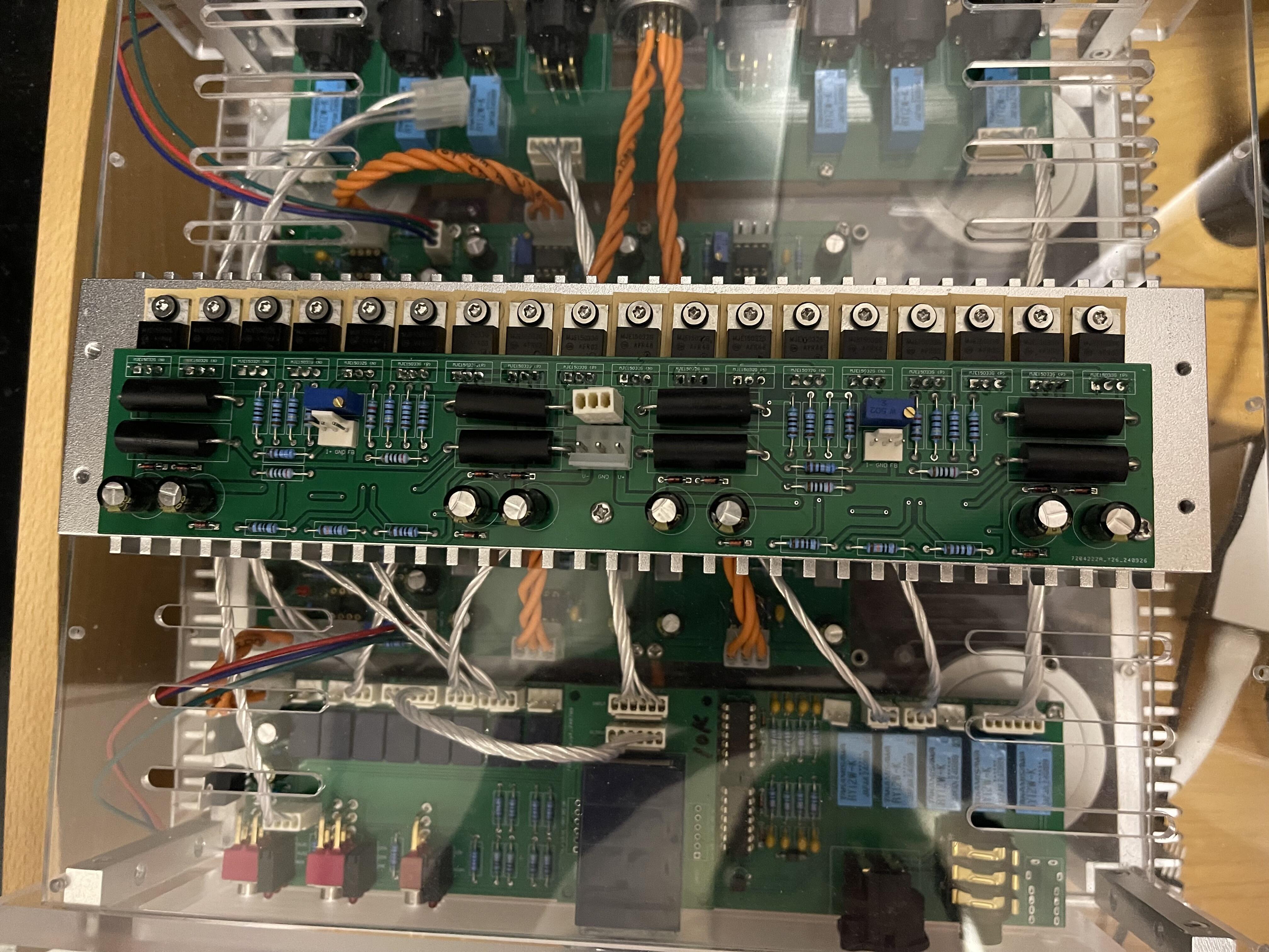
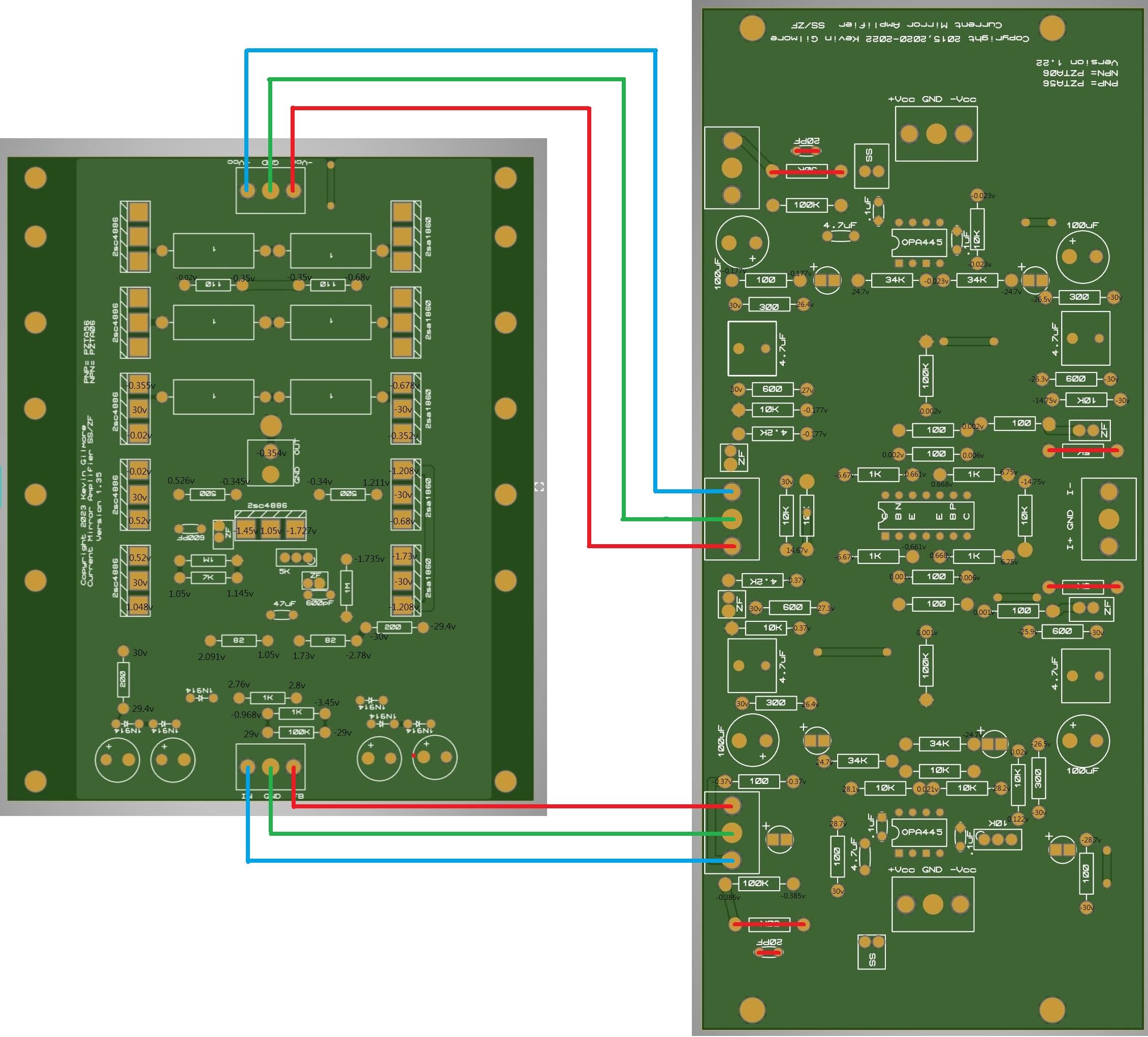
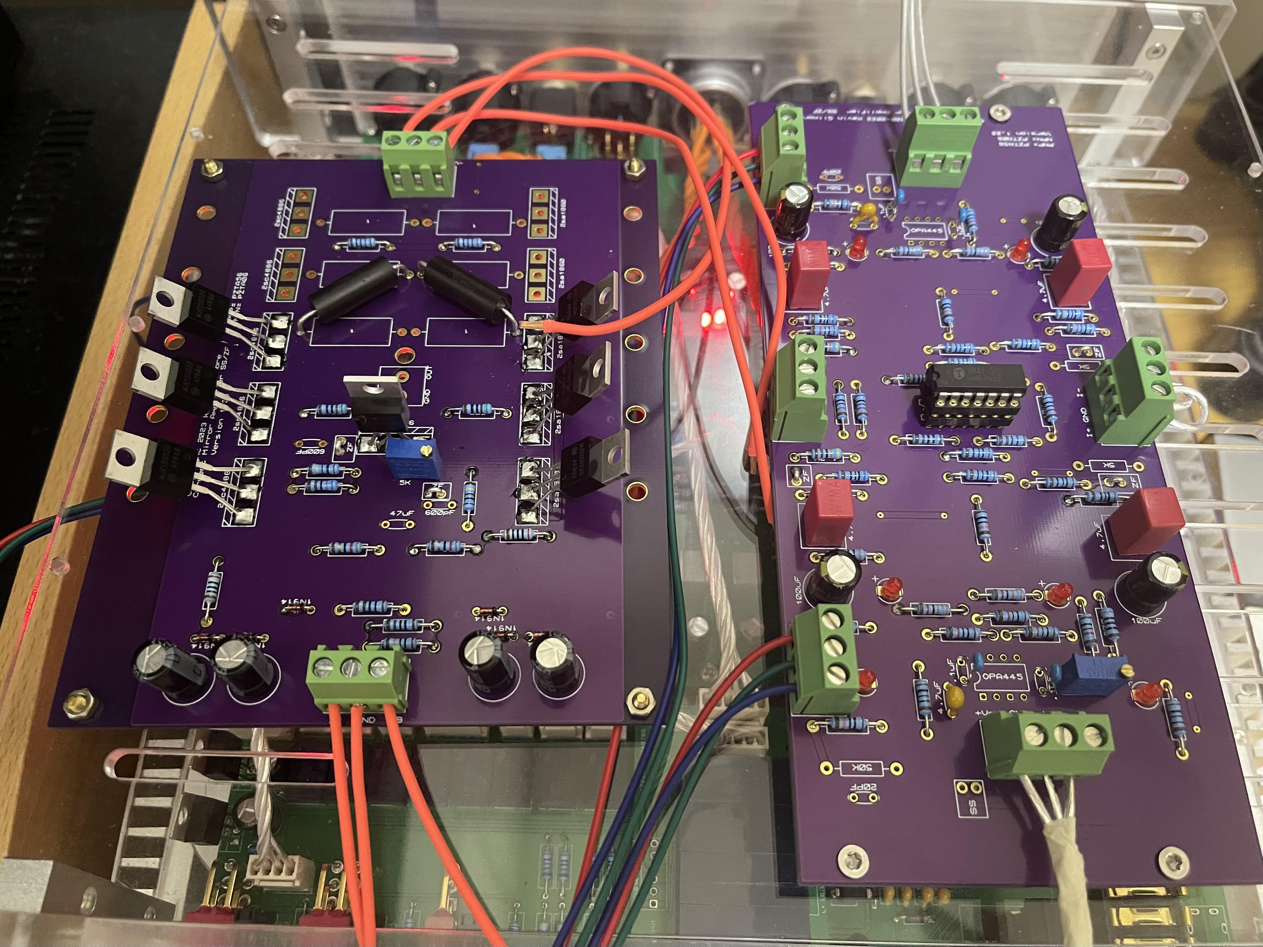
Hi Justin, sorry for the misleading of the picture. It is because the picture I post is only for a test version for myself to validate if the schematic I draw has any problem. After building the Dynalo, it is easy to measure the voltage across 20 ohm. Yet, I cannot measure the voltage across 1 ohm after building the cfa3. Therefore, I make use of the previous printed original PCB from Dr. Gilmore to test if there is the same situation. Therefore, I don’t install the heatsink and test it with minimal components. Actually, this is my CFA version (with a 20mm width heatsink). At the beginning, I would like to create a standard 1U size, therefore, I am fine with the original size (the 3u height version). However, I would like to minimise the space after watching your design to 32mm width. Therefore, I start drawing the new board by referring to the published schematic and the board measurement to ensure the circuit is correct.
-
and now for something completely different part 3
arcanaking replied to kevin gilmore's topic in Do It Yourself
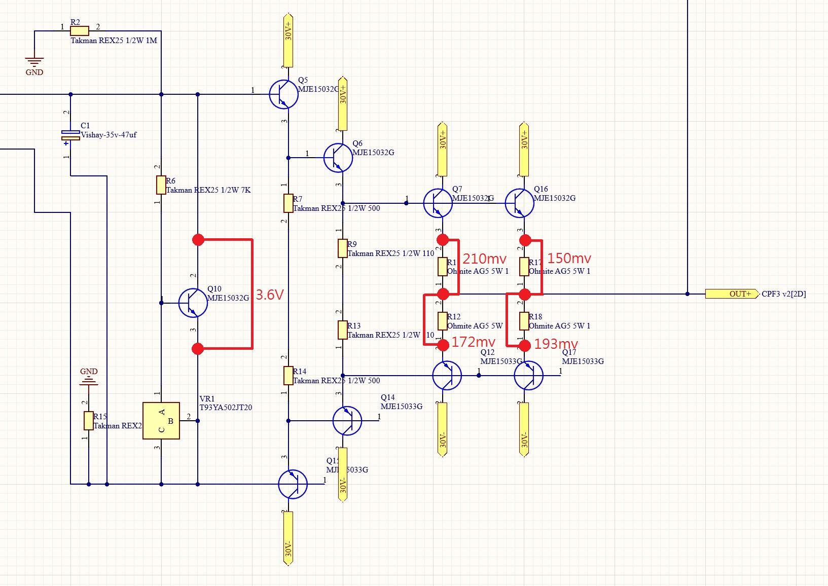
For the MJE15032 and MJE15033 version, I try to rotate the 5k trim pot at least 10 rounds. Until the the voltage across the Q36 (also call Q10 in my schematic) greater than 3.3v, the voltage across the 1 ohm start changing. When the voltage across Q36 comes to 3.6V, all the voltage across 1 ohm comes to 150mv to 200mv range. This measurement only rotate the 5k trim pot, and the 10k trim pot does not rotate (just for a little record) and stay in the middle point. Only one side of the CFA3 amp board (L+ channel) has already generate a great heat to the heatsink after 5 minutes in a fanless environment which suprise me a lot (the heatsink is around 20mm).
-
and now for something completely different part 3
arcanaking replied to kevin gilmore's topic in Do It Yourself
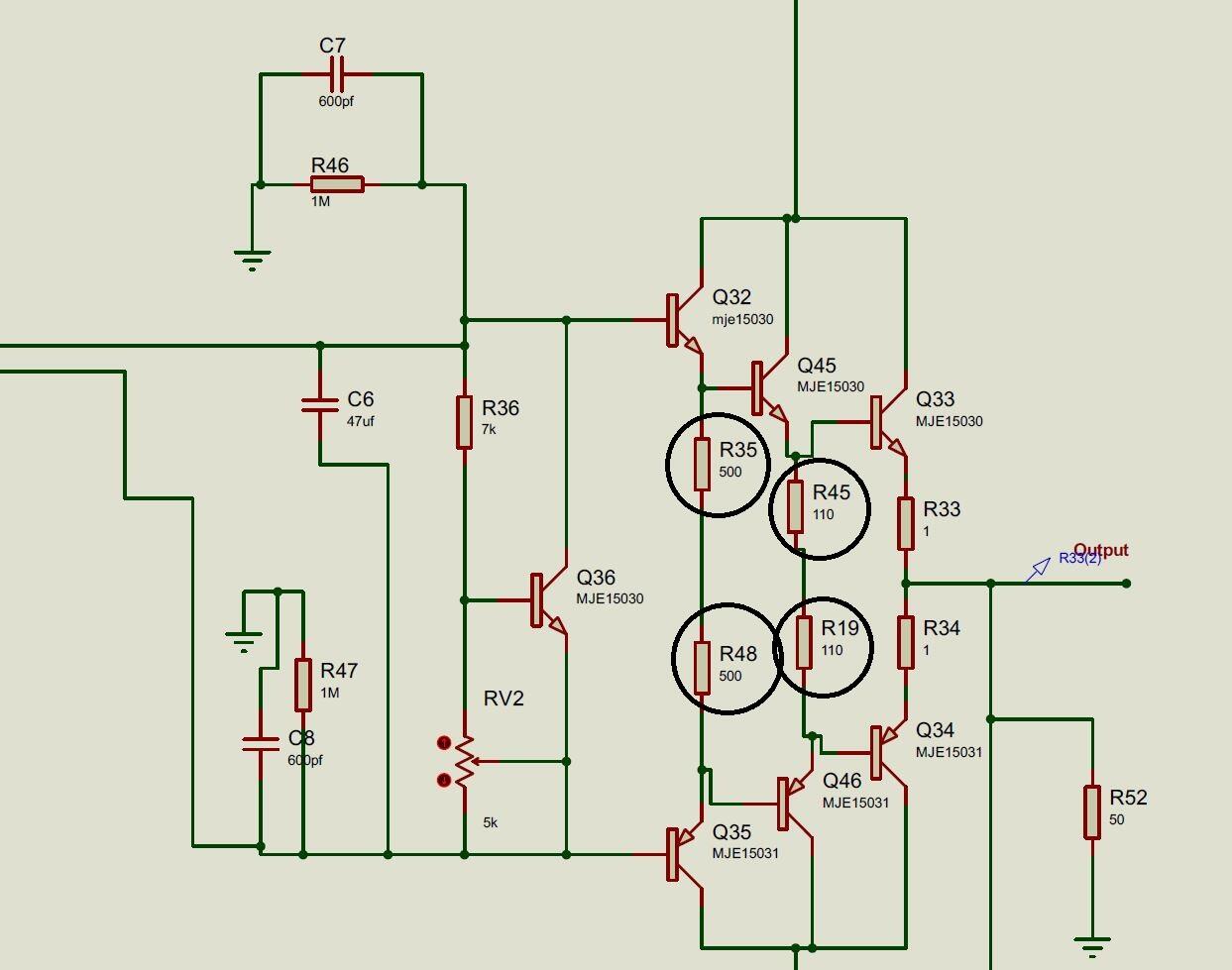
Currently, the power supplies is +/-30v. I have ordered some mje15030/15031 for further test. Also, If I have to change the resistor in the bias generator for the output transistor, which resistors should I change? Does the 500ohm and 110ohm in last output stage? or more?
-
and now for something completely different part 3
arcanaking replied to kevin gilmore's topic in Do It Yourself
The output board name is cfp3largeT.zip which should be posted on 11 Jan 2023. I try to measure and record the voltage between each pin and the gnd.
-
and now for something completely different part 3
arcanaking replied to kevin gilmore's topic in Do It Yourself
Hi all, I am following the schematic from the document "cfa3productionss.pdf" to build the cfa3 zero feedback version. I make use of the verion 1.35 board as a reference for the later building. After checking all the components and soldering to the pcb, I found that there is no mv when I short the input and measure across the 1 ohm. The 2sa1860 is replaced by mje15033 and the 2sc4886 is replaced by mje15032. The 47uf cap is smd. After I switch the amp for 30 mins, the smd bjt is hot but the 15032 & 15033 bjt is cold. Is there any wrong implementation for the cfa_amp board that lead to this situation?
-
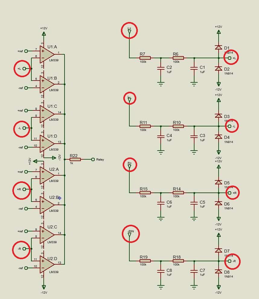
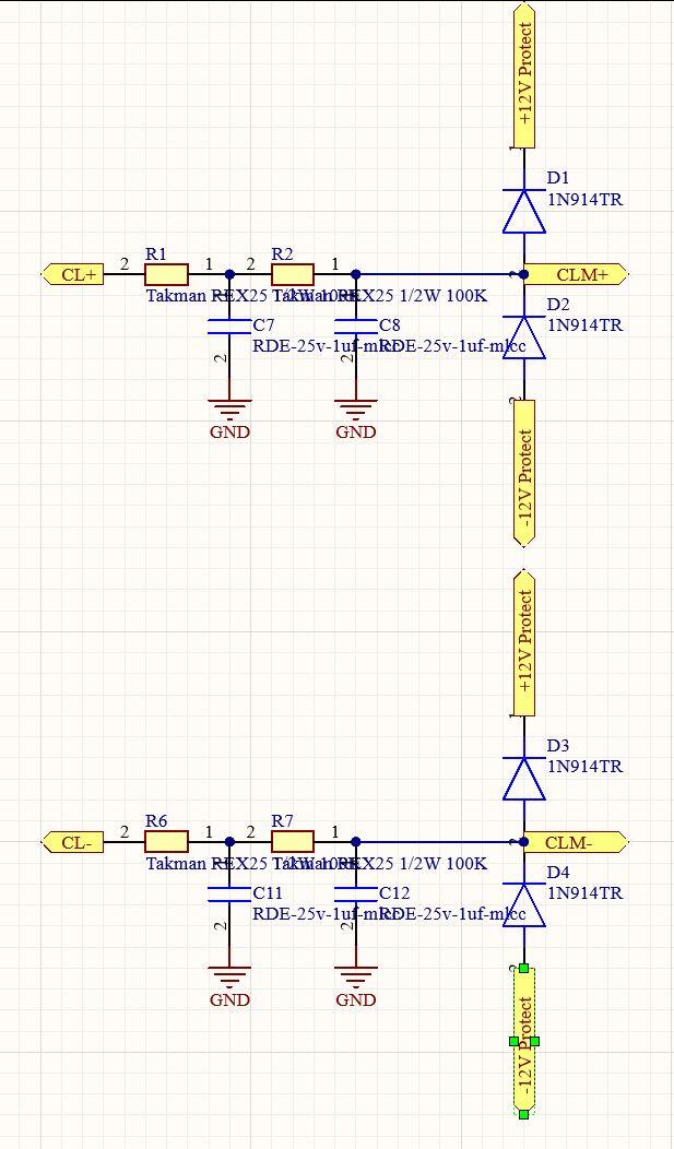
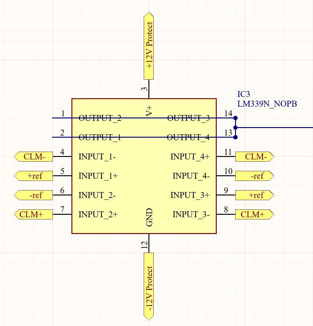
Hi Dr. Gilmore, I finally fix the problem. Sorry for giving you a wrong insight of the malfunction of lm339. After a few day, I attempt to change the mind to lm339 work fine in the circuit and I finally witness the problem. At the beginning, I focus on the circuit in lm339 but overlook the input signal part. The reason that the output mute after 11 o clock is because the input signal bypass the 100kohm resistor and directly feed in the lm339. Therefore, the voltage will larger than the ref voltage and trigger the protector to mute. My schematic is following JoaMat's version and the lm339 part is following the protect v1.0. In the input part, I follow the port label design and I think they are the same labels. Therefore, the altium designer will define it as the same and bypass the 100k and the input signal to the lm339 will over the ref voltage. After I change the labels into two group, the new board works fine even the volume is over 11 o clock. Again, Thanks for your opinions.
-
I tried the following things. 1.) solder the protector part in the new board. 2.) add another 2 100uf and 0.1uf caps near the chips. 3.) put 7812 and 7912 near the chips. 4.) by pass all the unrelated relay and keep the protector relay only. 5.) by pass the lm339. 6.) check the components and circuit direction with the multi-meter. All the new components in the new board with 1, 2, 3, 4 still cannot solve the problem. I also check the circuit with the multi-meter in comparison to the protector v1.0. It can make sure that the route has no problem. In 5, the bypass of lm339 has no problem, this ensure that other relays works fine. Therefore, I am curious that if the width of the route for power supply will also affect the performance of lm339 (all the width of route that related to lm339 is 1mm except the power supply route is currently 0.5mm).
-
Thanks for the advice. Does the distance of the 0.1uf cap affects the effect? I will try to solder the .1uf cap near the chips. The relay coils have diodes. For the protector (2nd in the right hand side), it will pass through the 1n4007 like the original protector board. For other relay coils in the right hand side, the led act as diodes across the relay coils in the left hand side.
-
Sorry for the inappropriate link. Here is the full board. I will later provide another full version of the board from altium designer. Here is the full board. Edit: Here is the board.
-
Hi, I am building the susy dynalo and cfa3 with the protector board. The protector board works fine unless the volume knob turn over 11 o clock. If the volume knob is below 11 o clock, each pin's voltage is normal (Pin 1, 2, 13, 14 is 7.9v, pin 5 & 9 is 0.54 and pin 6 & 10 is -0.49). If the volume knob is over 11 o clock, all the pins' voltage remain the same unless pin 1, 2, 13, 14 keep changing between negative and positive voltage. The switch will auto mute the output. When I change this protector board to the original protector 1.0, everything works fine even the volume knob is over 11 o clock. What is the cause of this problem? Thanks.
-
goldenreference low voltage power supply
arcanaking replied to kevin gilmore's topic in Do It Yourself
Thanks jamesmking. I finally find out the reason. Thanks for your suggestiosn. I switch the multimeter to dc voltage to check the transformer and capacitors and I finally notice that the right cap is flipped and I use the negative pin to connect the ground. I misunderstand that all the capacitors should connect to gnd by negative pin and thus the capacitor cannot discharge. After I flip back the cap, everything work normal. Thanks again for helping me to tackle the problem.
-
goldenreference low voltage power supply
arcanaking replied to kevin gilmore's topic in Do It Yourself
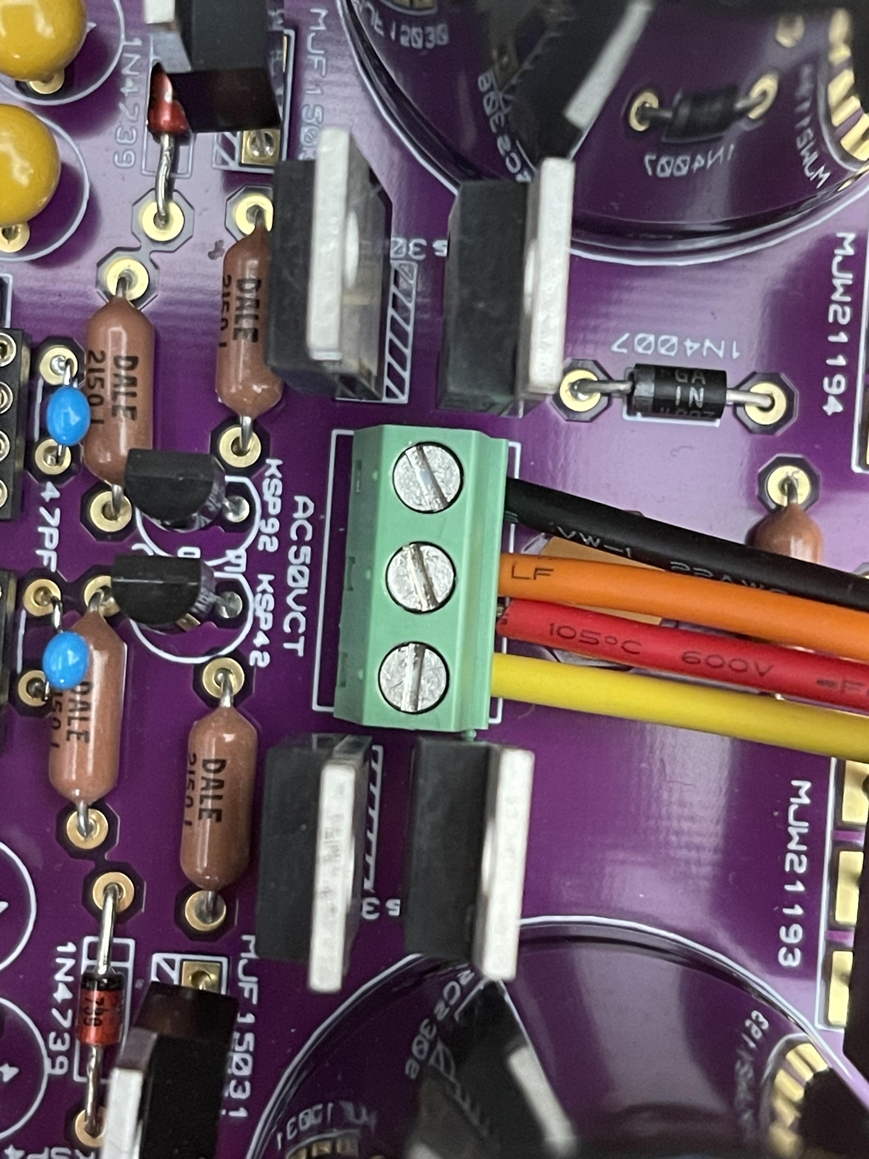
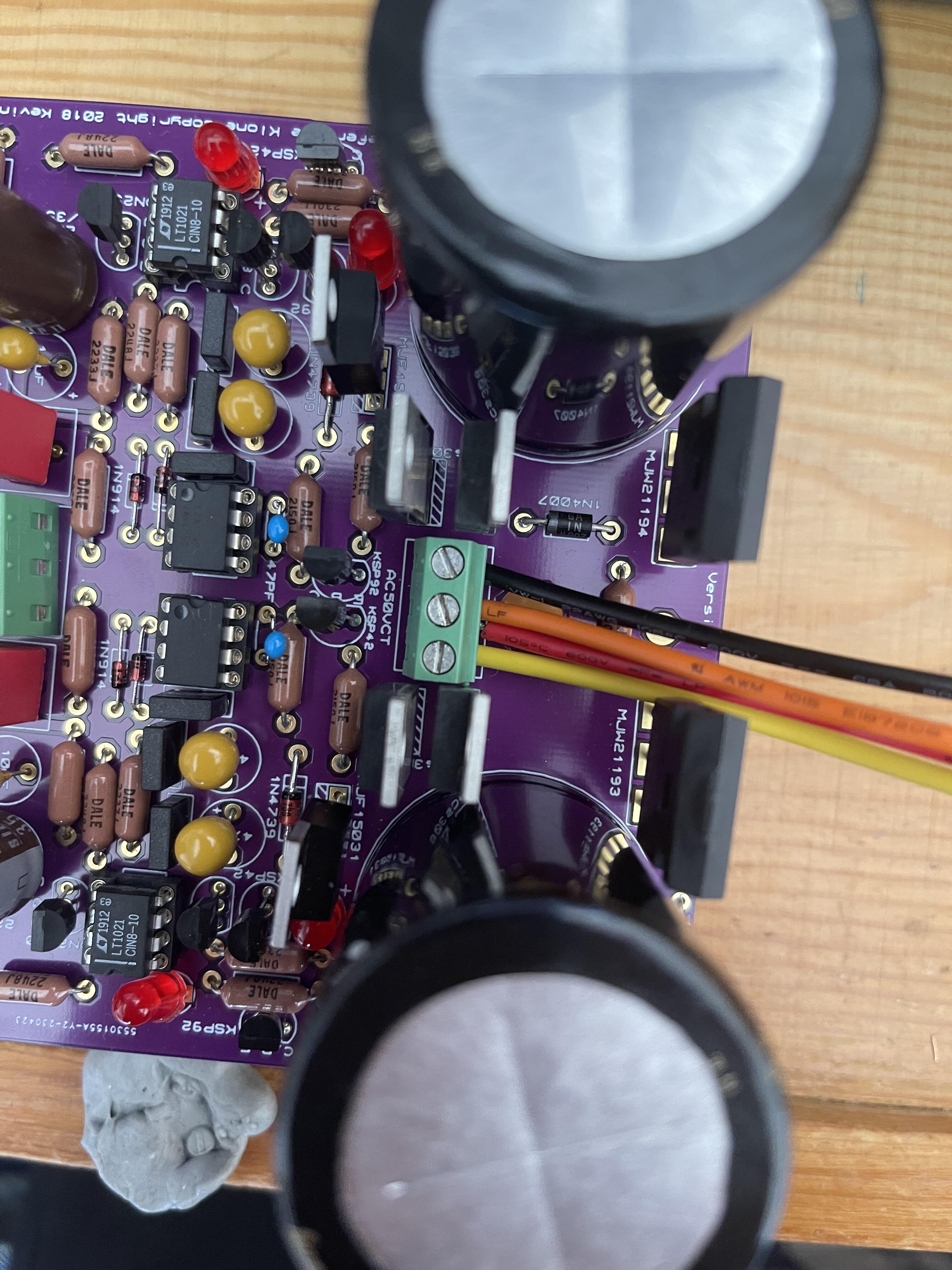
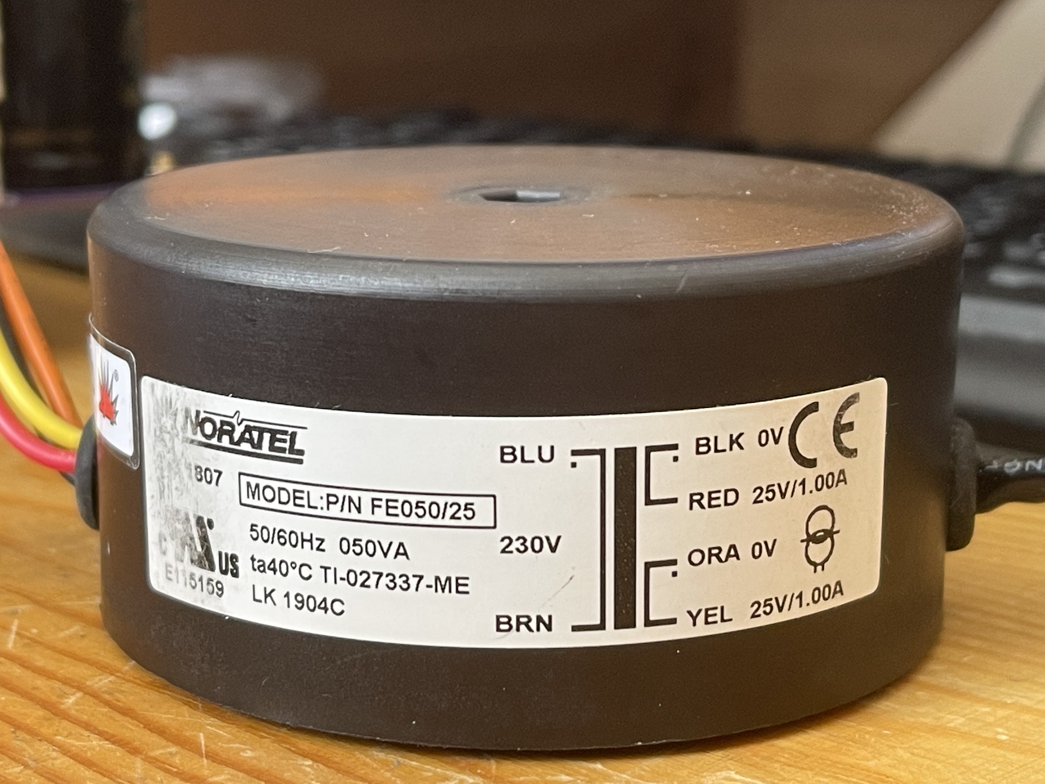
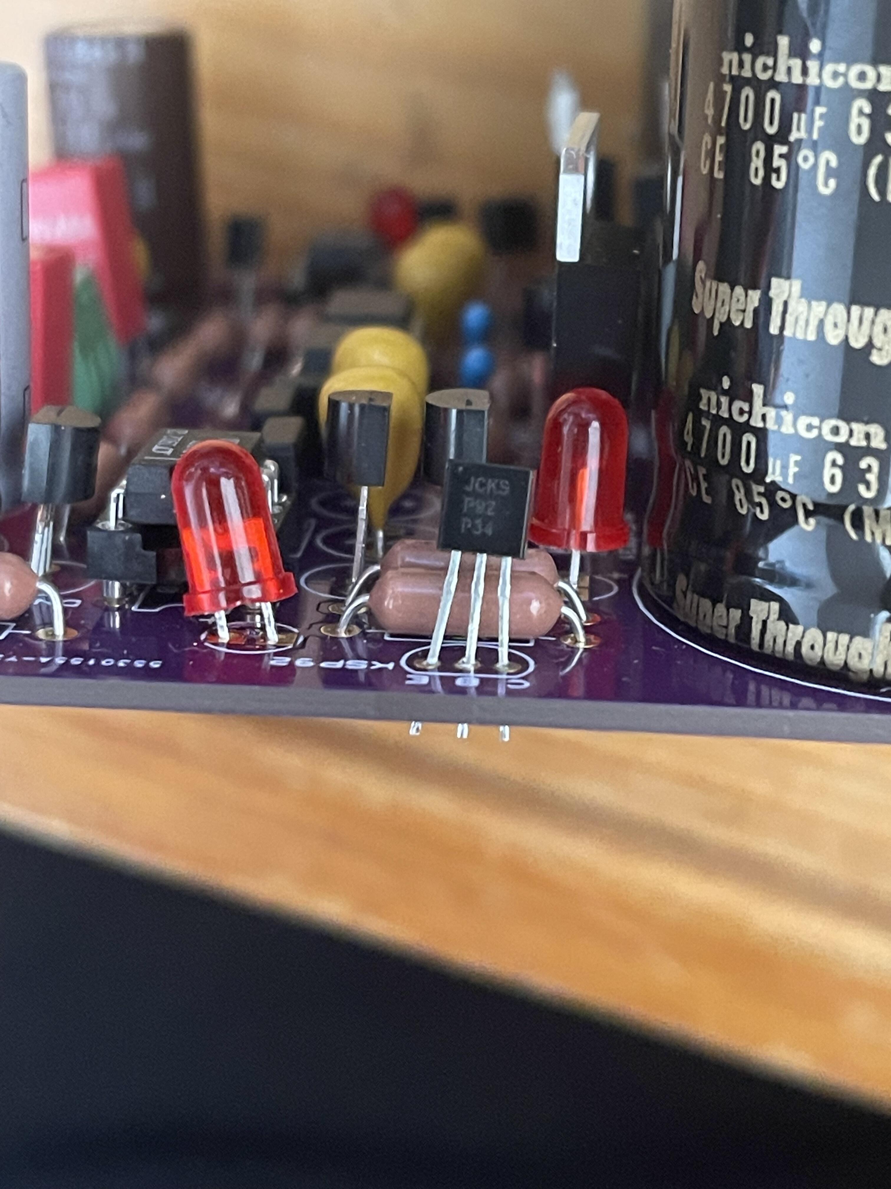
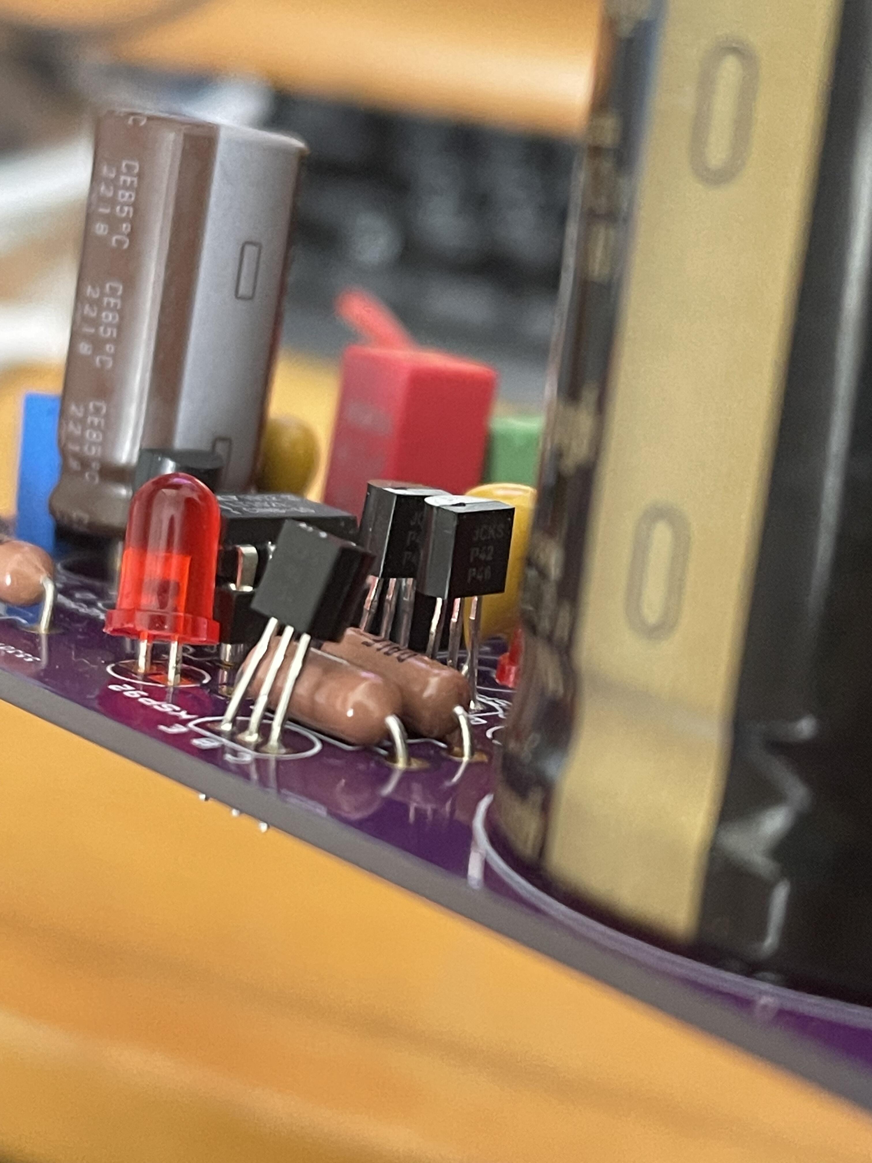
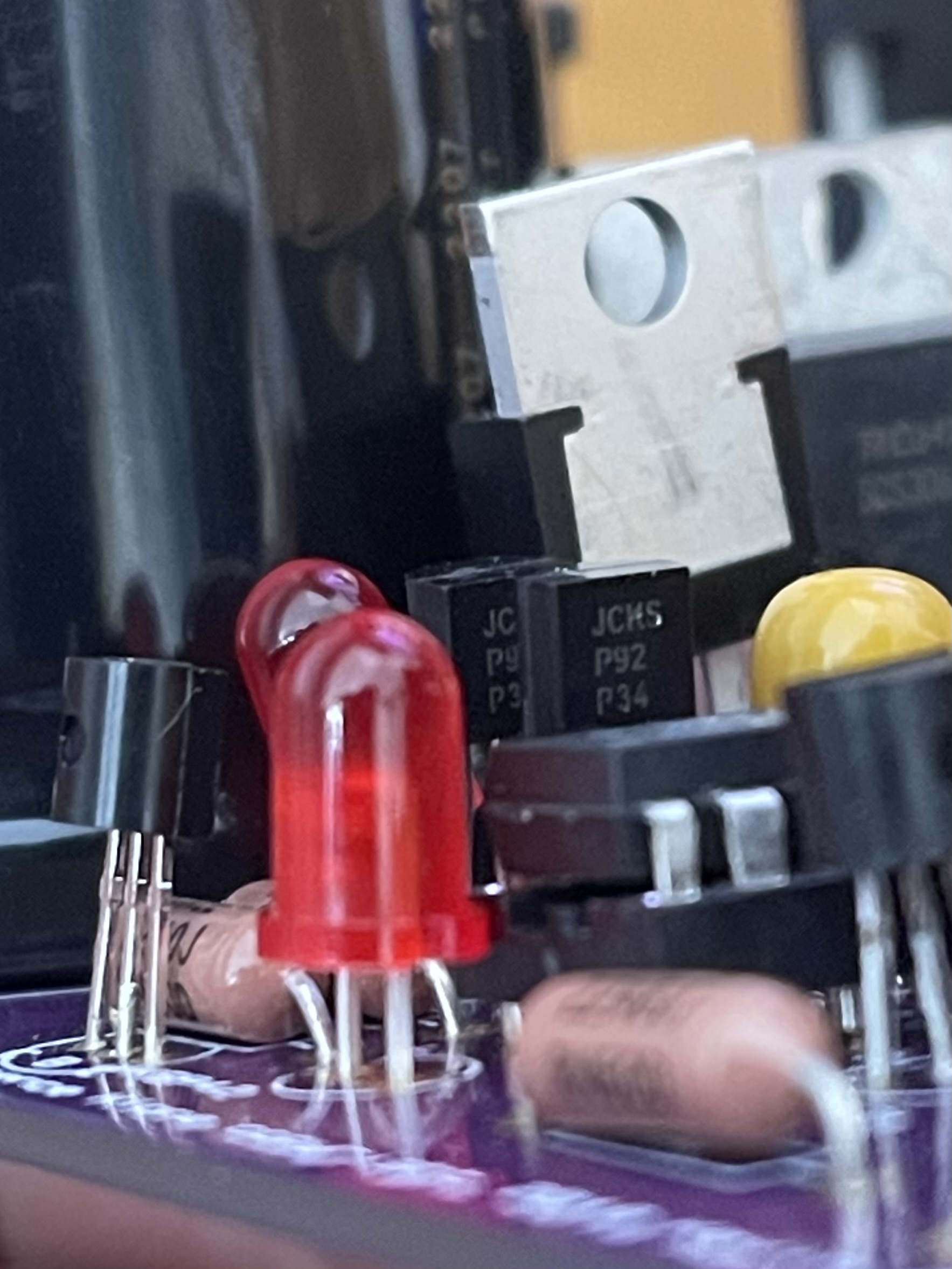
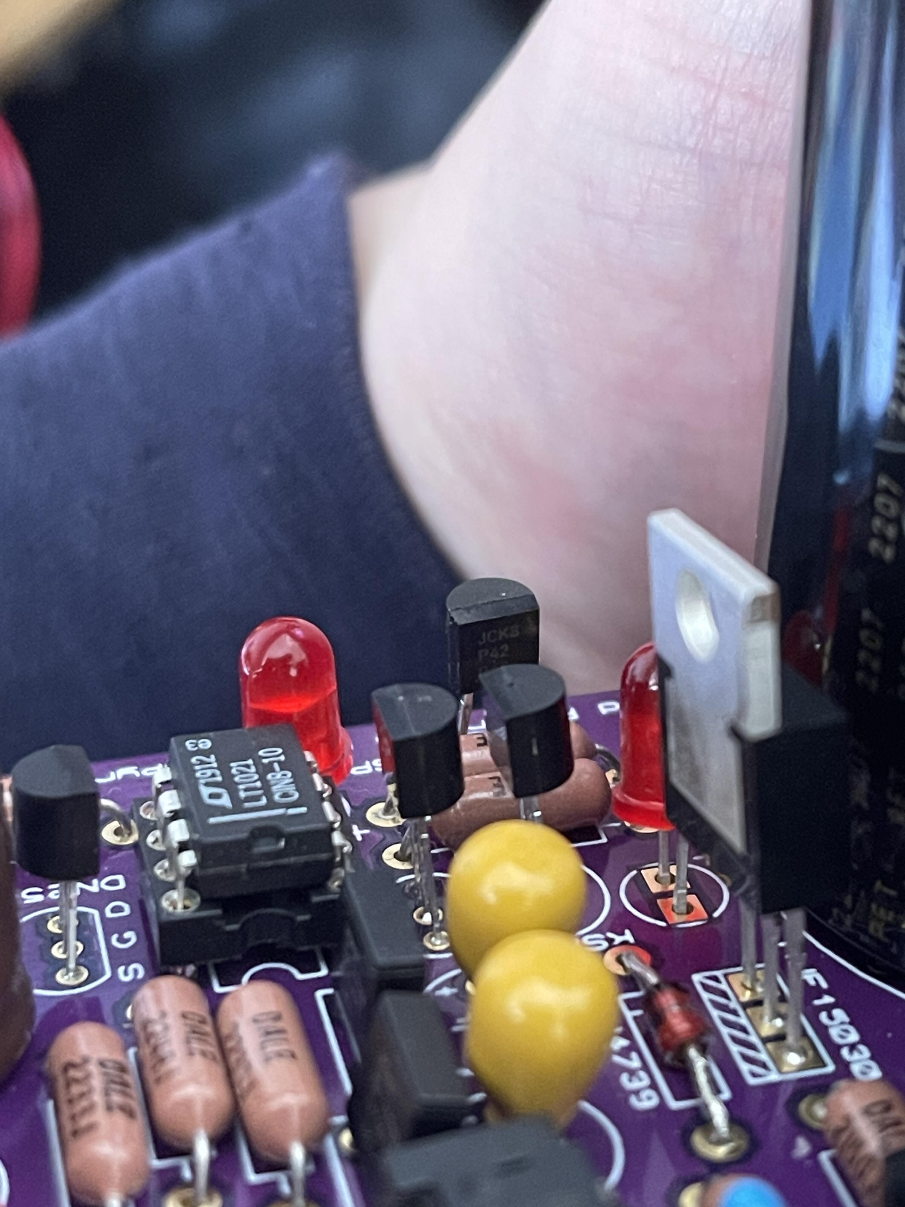
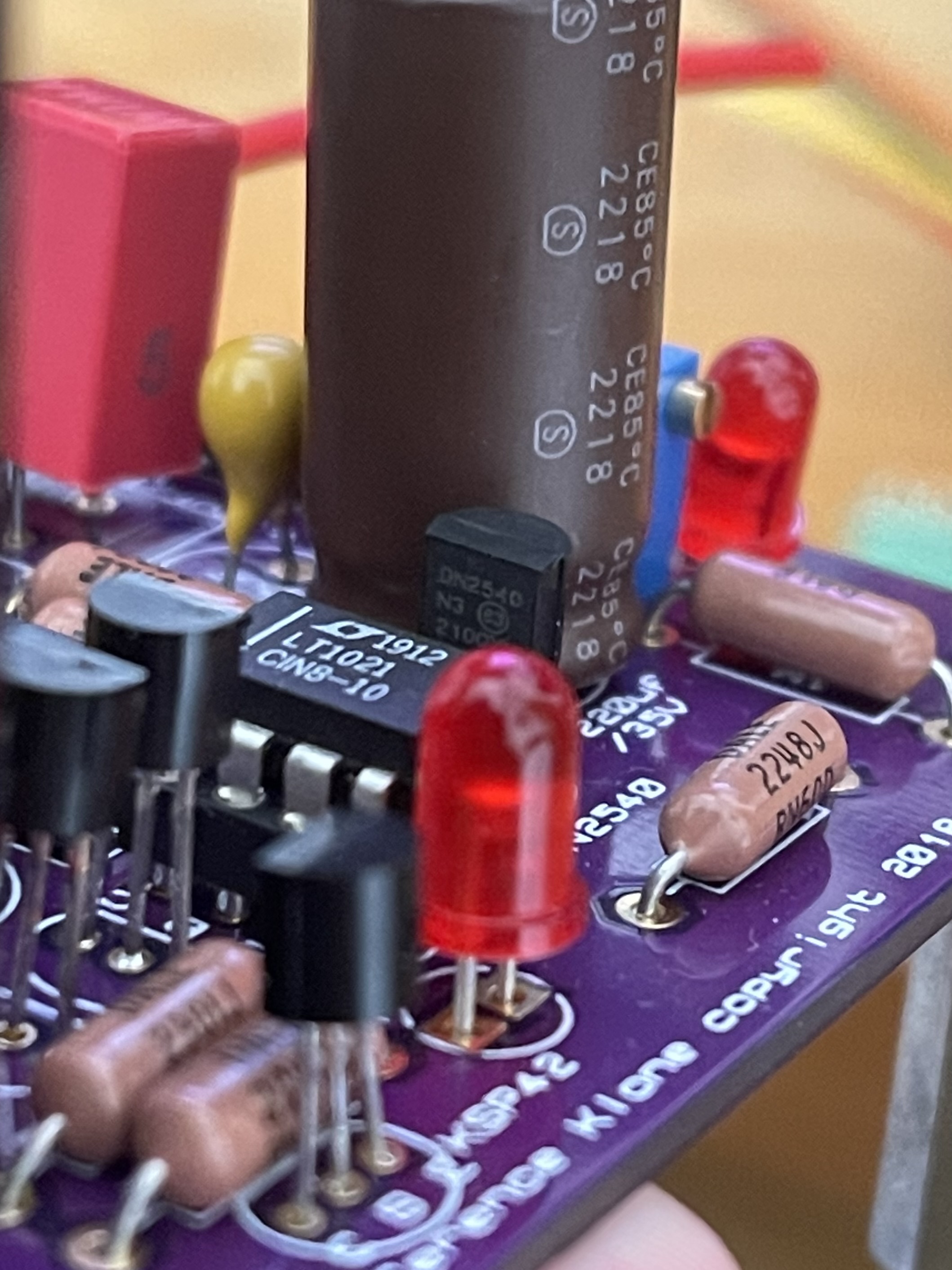
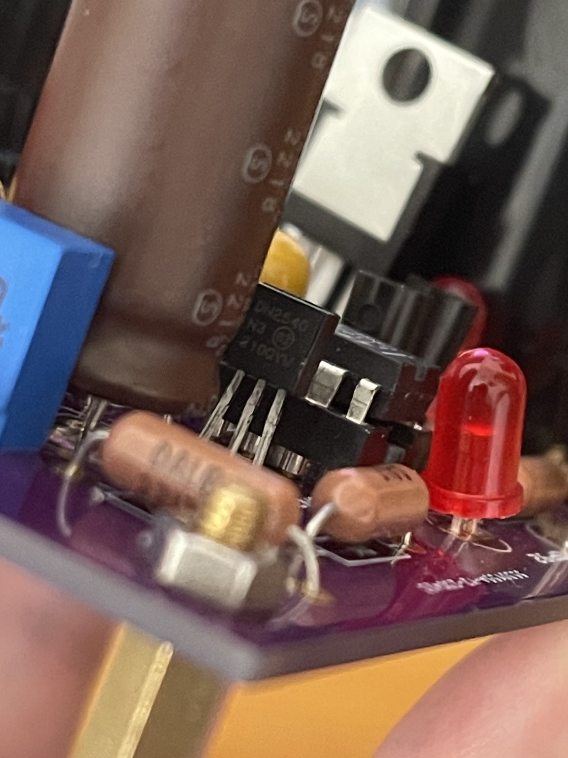
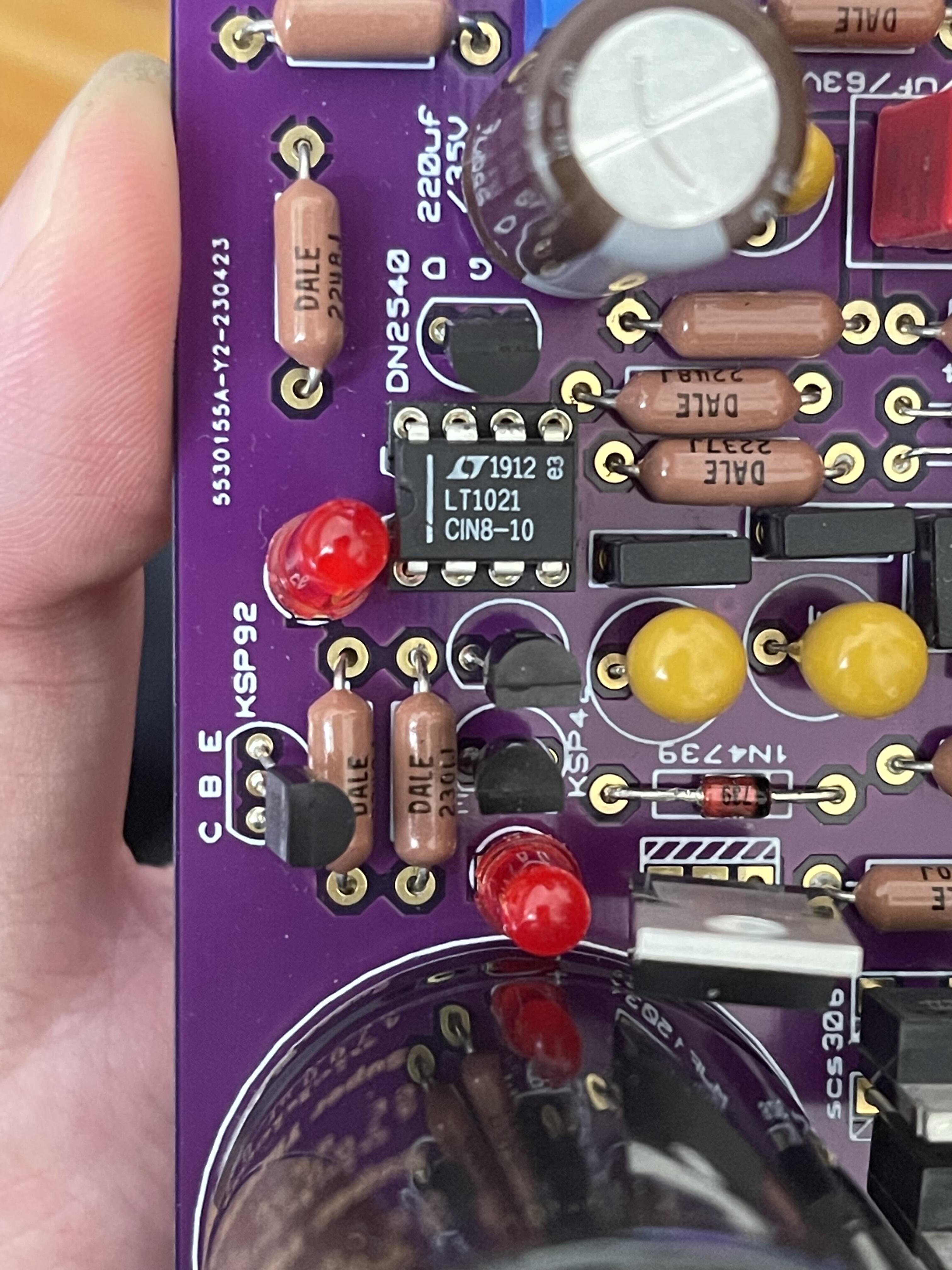
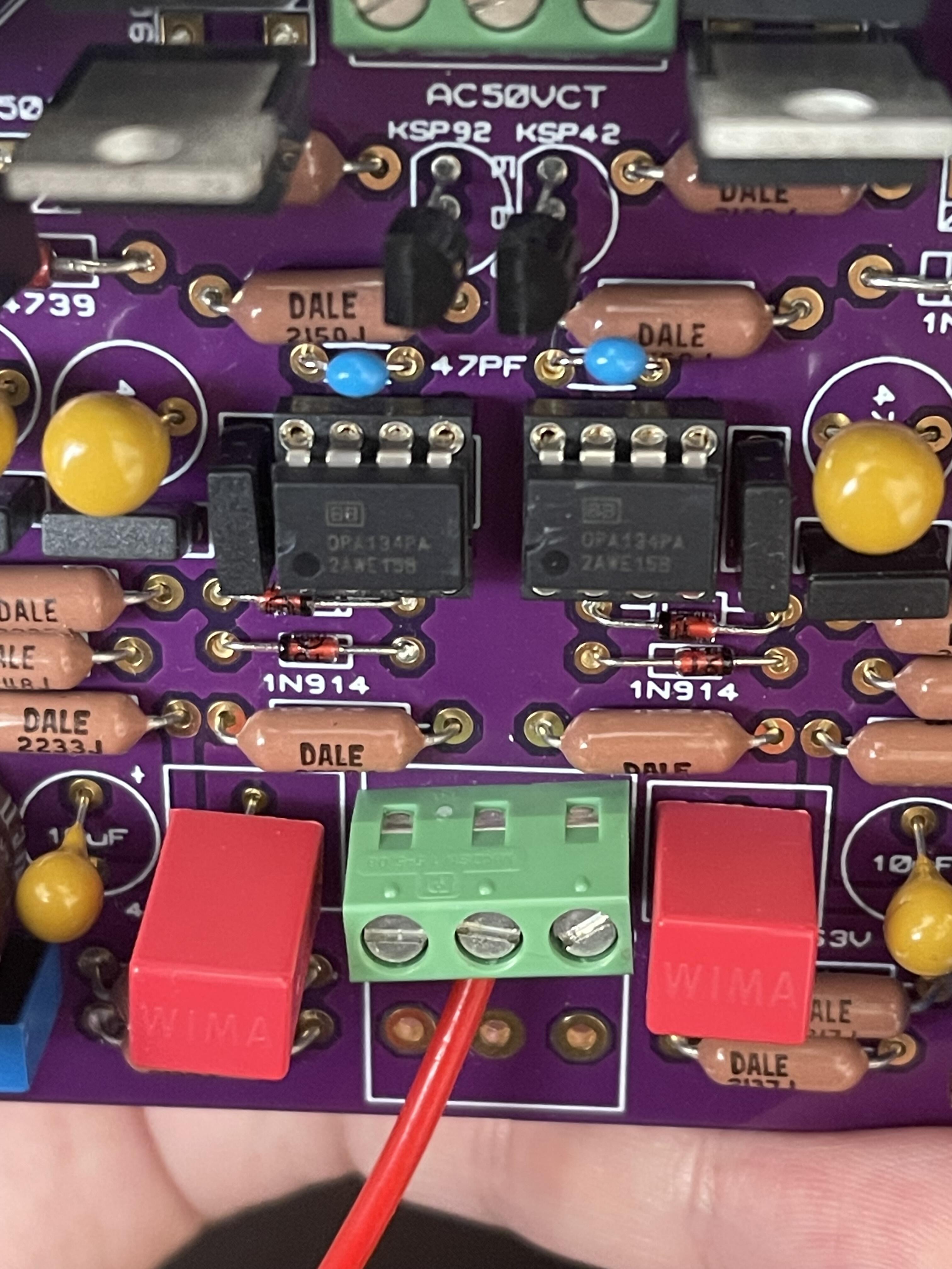
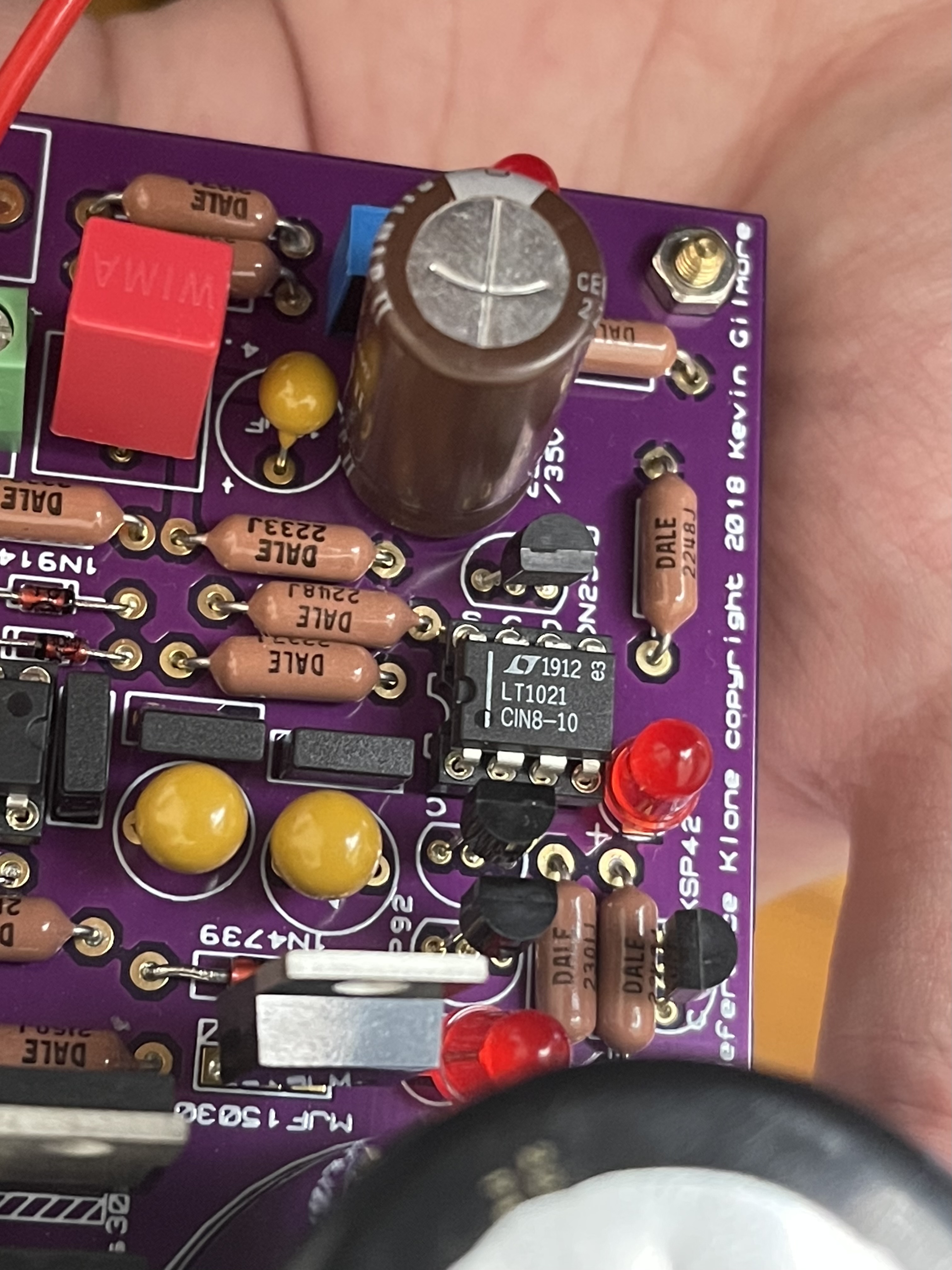
Thanks jamesmking. This is my transformer's information. It is a 50VA 25V toroidal transformer. I shorted the red (25v) and orange (0v) and connected to the gnd. Thus, it will perform 50v output when the probes are on the left and right pad in input socket. I have tested the voltage reference as the guide, the positive side is 10v in stable. Yet, the negative side starts with 10v and drops quickly. Most of the parts are from mouser. Only some DN2540N3-G, MJW21193G and MJE15030G are ordered in Element14 because mouser has no stock currently. Here are more photos of the components' details.
-
goldenreference low voltage power supply
arcanaking replied to kevin gilmore's topic in Do It Yourself
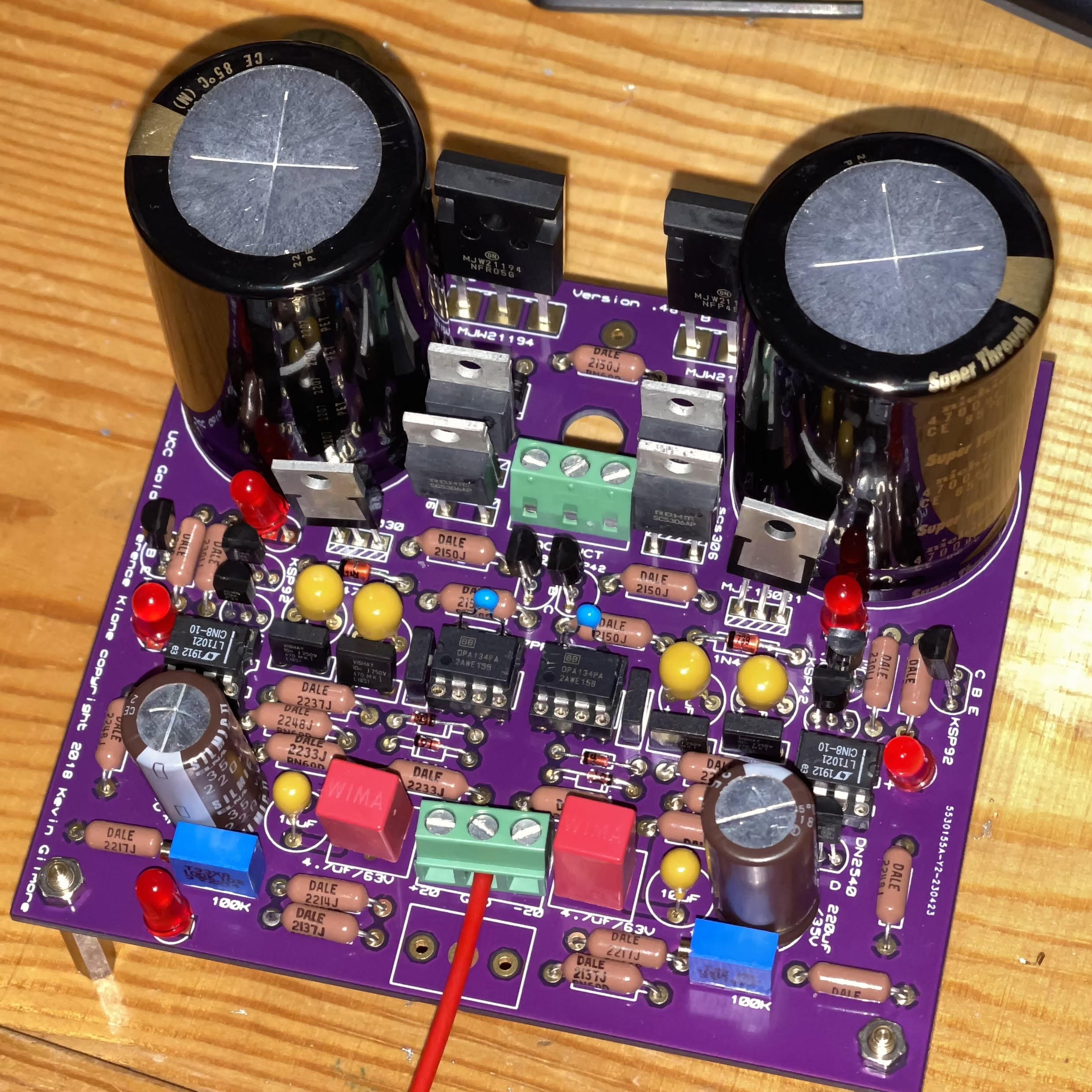
Hi All, I am building the GRLV 2018 version.48 and I get a problem which I have no idea to tackle it. Before I soldering all the parts, I checked the position of ksp92 and ksp42 and confirmed they are put in the correct position. When I plug the 50VA transformer to provide double rails 25v to the GRLV, all the LED will light up but only the LED which near the zener on right side will dim soon. I use the multimeter to check the output voltage and I found that the positive rail provide stable 20v but the negative rail will keep dropping the voltage every second from 20v. Can anyone tell me why the negative rail keep dropping voltage? Do I mess up the polarity or put the component in a wrong place and thus lead to this problem?
-
and now for something completely different part 3
arcanaking replied to kevin gilmore's topic in Do It Yourself
Hi all, sorry for requiring the pdf/gerber. I am trying to build my CFA3 with the balanced audio protection board. Yet, it seems hard to find the gerber or pdf of the protection board in other threads. Can anyone tell me if it is a must to use the protection board? If yes, where can I find the document?

.jpg.f5239839f2d5cda4da974f4a16295d1e.jpg)