yabba235
-
Posts
32 -
Joined
-
Last visited
Content Type
Profiles
Forums
Events
Everything posted by yabba235
-
This apex chips has no any radiators - very poor design.
-
This is exactly what I wrote in the first post - the diagram is not the same as the connections on the board.
-
OK, thanks for explaining - best regards!
-
Did you run it with lsa389? What did you change in the schematic? Have you considered using the SOIC version instead of the TO-71 transistors?
-
Kevin, one more questions: under original schematic resistors r45 and r46 is connect between base q19/20 and emitter q23/24. But in real pcb is connected to base q23/24. I checked it a few times, no mistake - I do not know what to think about it...
-
Thank's !
-
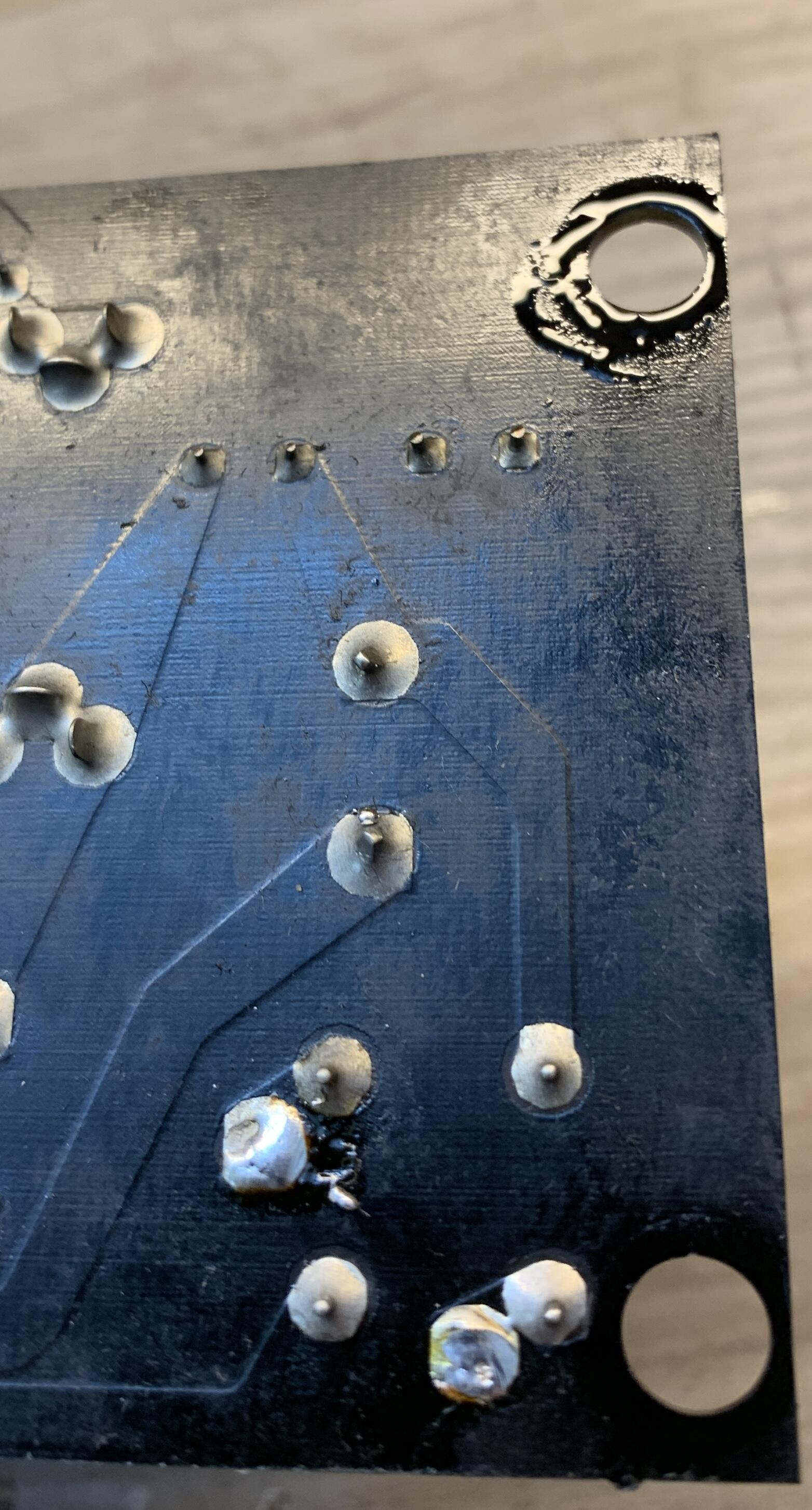
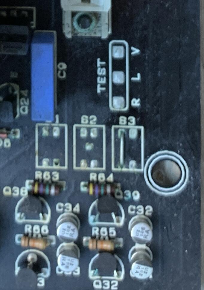
Hi! I am renewing 25-years 717's and I observe strange things: I noticed a lot of wet places - as if sweaty - I suspect it has something to do with high voltage, have you noticed such symptoms in your old Stax? It's probably old flux - but these are places where it shouldn't be - output sockets, bottom of heat sinks (between PCBs). The second issue - how does the output protection system work - it draws voltages only from two outputs +L and +P? Because that's what I saw on PCB. What are the soldering points marked 81,82, 83 and Test: R,L,V for? I know that Kevi n had a diagram of this system somewhere, but it is no longer available .

-
To bad I can't buy it - my only contact with Chinese products is through Aliexpress, but there are no such products there. Since you have it on your table, can you give me some details about its power section? What kind of system will be used, probably none of the modern dc/dc controllers. Maybe a similar system to the old SRM-252S?
-
spritzer, If it's not a problem, I'll be happy to buy this scrap from you - contact me on pm
-
Hmm, from the translator: "..Portable (Class A) electrostatic headphone amplifier supports DAC decoding Completed the development of the latest portable electrostatic amp, surpassing Stax D10, Sennheiser kse series and domestic products of the same series, push-pull structure, the latest design, the first in China, adaptable to stax or other stax-5pin standard interfaces, and a full range of bias 580 products Speaking of why it surpasses most portable electrostatic amps on the market, the reason is that this structure is a COMS current mirror push-pull design. Class A portable electrostatic amplifiers on the market are all class D. Fans should understand the difference between class A and class D power amplifiers..." Sounds familiar.....and quite avant-garde housing design
-
It's not that bad, apex's integrated amps are good enough. As for the transformers on the outputs, I say no to them!
-
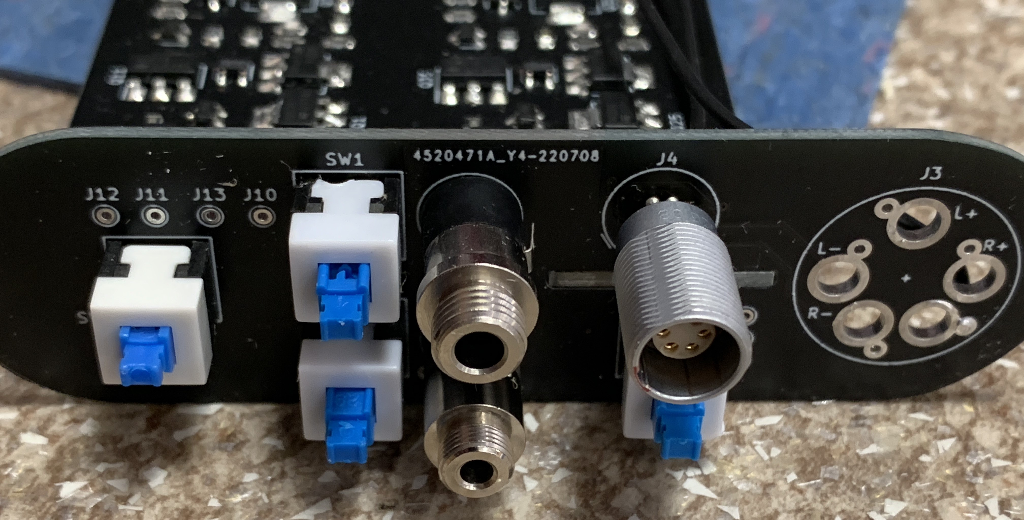
Only a few: bias voltage selection, input selection ( bal/unbal) and power on/off. The first two are implemented based on bistable relays - connecting them requires only momentary power consumption - important when powered by batteries. Last is simple monotstabile switch. Because of the relays, the housing is large, but maybe someday I will find smaller relays or think about another solution. (Instead of a discrete stage, I would see a high-voltage OA here :))
-
Can you have contact with him? I am also happy to buy these modules. I found them myself a few months ago ( find my post on diyaudio forum) but I have no friends in Japan. Without these chips I will not finish this amplifier.
-
As for your pcb board: You have big cohones, dude !! BTW: Can you share the source of lt8365 chips in japan ? - I can order them there because only this is what I still need to finish the project.
-
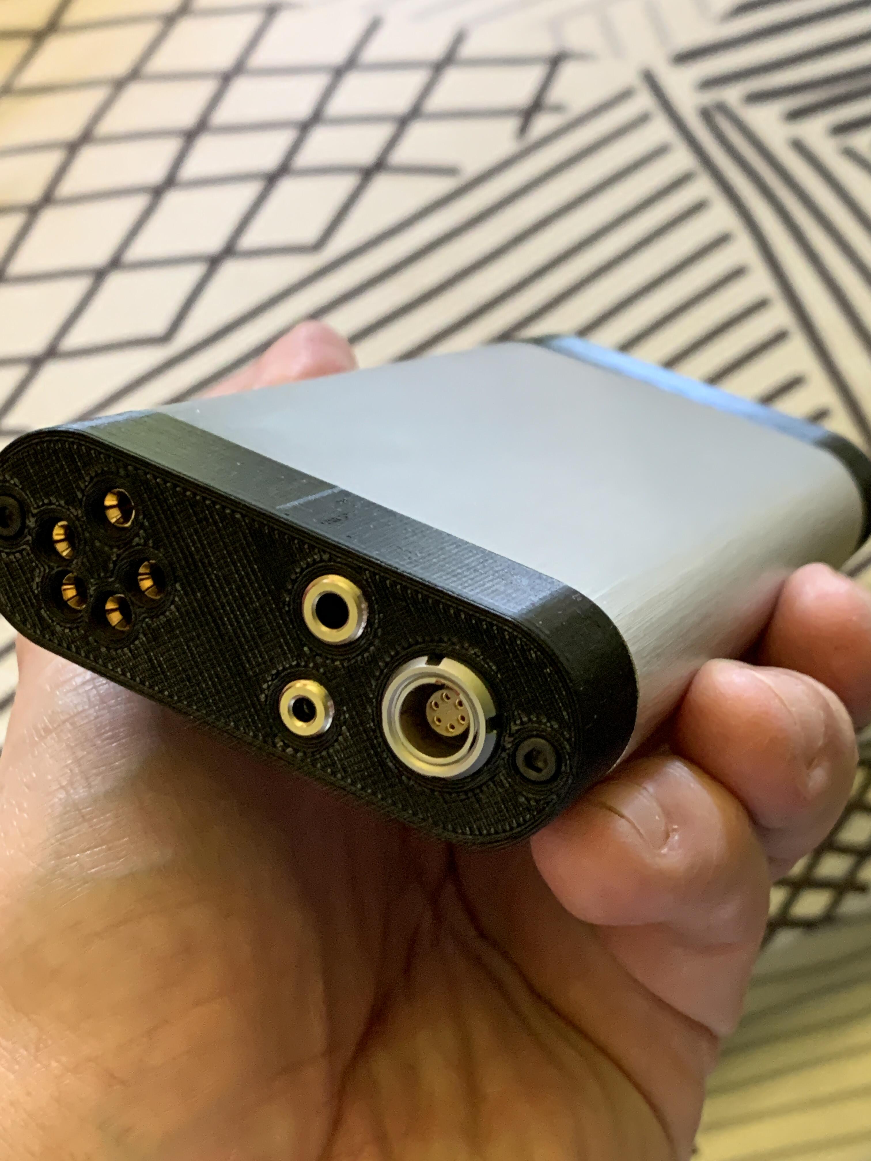
Inside is Kevin Gilmore estat portable with my modification and you can't buy it - it's d.i.y.
-
Born in pain - no semiconductors on the market- but case is here ! Introduction my portable estat with necessary modifications
-
Got it, thanks for explaining this !
-
Hi ! I get this unit, but I'm confusing with offset voltage - I measured the output offset voltage and it is far from 0V - I do not know if these stax amplifiers have that, but mine has, respectively: 8.8V, 5.4V, 12V and -0.6V? Electrostats are rather new to me, but here the DC voltage at the output should be close to 0V, as in conventional amplifiers? Is it not damaged? Does anyone have a list of the correct voltages in this model?
-
Now all works - I had a short break with electronics so I was a bit rusty
-
Thank's, but my problem is when I connect them single amp like on a kerry pcb together, the simulation does not work. And I can see that it works in real - maybe I'm doing something wrong in the simulation ??
-
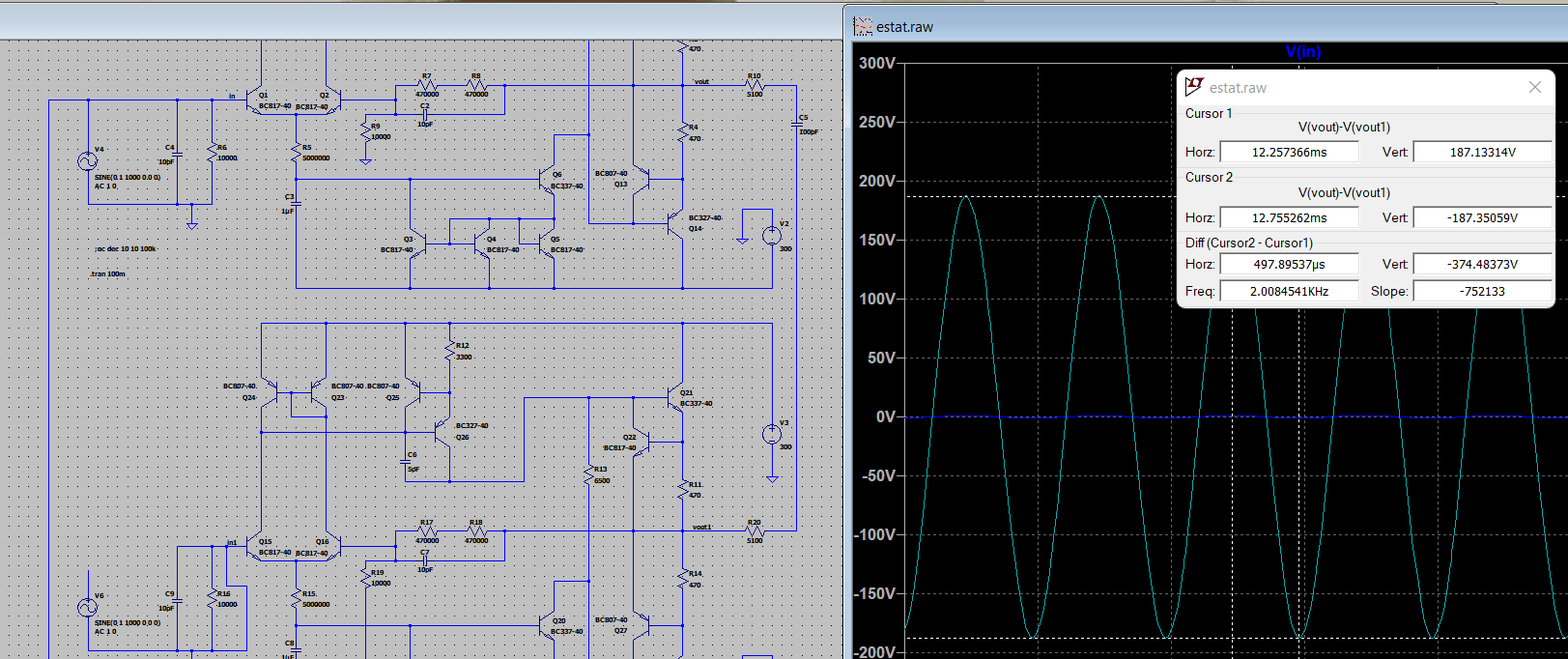
Nice joke I simulated your schematic in topology from pcb and it does not work in any way - only in single mode, not bridge. And I know it works to you - some "king of magic" I always liked to check the circuit in the simulation before I did something - we have something in common
-
I have a certain idea - you could add a direct input for a balanced signal - my qudelix gives 4V rms in this mode - bypassing the potentiometer, which is not of high quality - anyway, it is unnecessary in this configuration because the gain control is taken over by the phone or the qudelix itself (of course it writes about my case)
-
I have one more, maybe a stupid question - how are these four amplifiers connected - there is no phase inverter there and looking at the pcb I can see that the inputs in the channels are connected (?) - I'm tired of this matter and I can't sleep because of it - can you explain it to me ?
-
I understand, and when will it be ready to buy?
-
stax mafia circuit boards see updated links on page 5
yabba235 replied to kevin gilmore's topic in Do It Yourself
Thank you !