audiostar
-
Posts
310 -
Joined
-
Last visited
Content Type
Profiles
Forums
Events
Everything posted by audiostar
-
Group Buy - Digital Attenuator (Kevin Gilmore)
audiostar replied to sorenb's topic in Do It Yourself
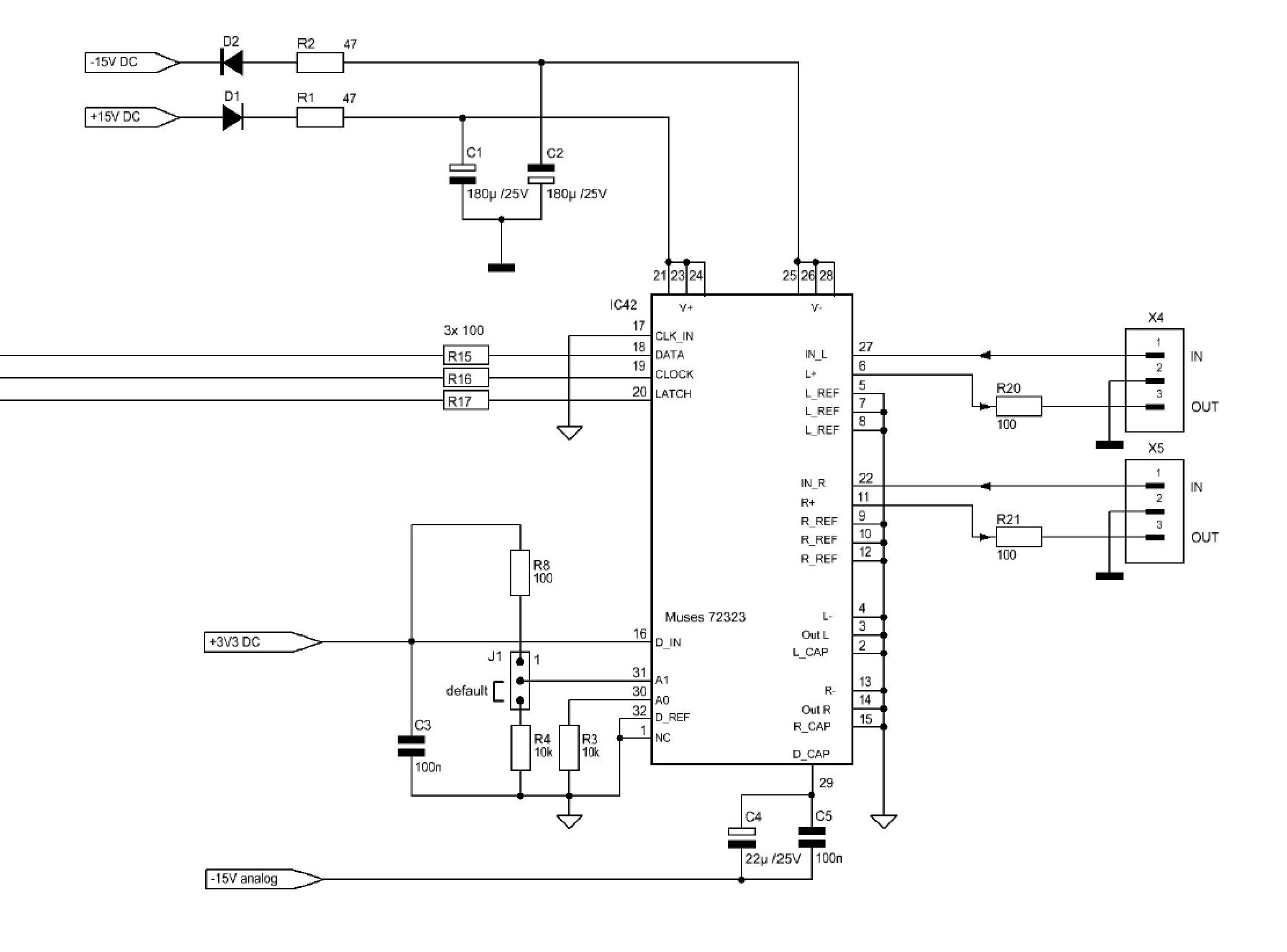
Here the actual attenuator based on the 72323 for one balanced channel (the 72323 already includes two channels, so + and - for us). The three lines on the left are coming from the controller. The jumper J1 sets the chip addressing for the left/right channel. Not sure if we need the 100R resistors on the output with Kevin amps, as well an opamp (like the Muses NJM2082), which according to the tech specs is recommended.
-
Group Buy - Digital Attenuator (Kevin Gilmore)
audiostar replied to sorenb's topic in Do It Yourself
Hey Pars, the BOM for that preamp says explicitly MUSES72320, are you sure you want to buy the 72323? The 72323 is the newer chip, has better specs, need less external parts and is cheaper. Unfortunately not compatible with the the older 72320. We should be able to take out the volume control portion of the code from there. I am making a balanced board atm that will sit at the amp's input and connect via cable to the controller board holding the encoder and the microprocessor itself. But the STM32G031K8T chip is sold out everywhere; ebay and AE remain only. -
Group Buy - Digital Attenuator (Kevin Gilmore)
audiostar replied to sorenb's topic in Do It Yourself
Looks like he is not publishing the control software! The ST controller chips are completely sold out everywhere as well. Otherwise flashing the software is pretty easy with a ST-link programming unit and their IDE and the hardware part is straightforward as well. Btw, nice balance control can be implemented (in software) as the chips can be addressed separately and 2 are needed for balanced anyway. The newer chip is the 72323, not much difference, if any. -
Group Buy - Digital Attenuator (Kevin Gilmore)
audiostar replied to sorenb's topic in Do It Yourself
Its very nice, 0 to -111dB with 0.25dB steps, highly linear. Controlled by a 3-wire bus. Sounds pretty amazing, used by Pass in the XP-30 as well. -
Group Buy - Digital Attenuator (Kevin Gilmore)
audiostar replied to sorenb's topic in Do It Yourself
All this time I was looking into the other thread for the digital attenuator and it took me a while to find this one with the actual discussion 🙂 The latest digital attenuator is a very nice one on a single small board for a 4 channel balanced amp, but without a control board it is not really easy, i.e. useful to people and I mean all people. It seems like Kerry is not giving his control board away as well; it looks to me he did take the Arduino Pro Mini schematic (which is pretty simple and open source btw) and included the encoder, so all on a single board to connect straight to Kevin's attenuator. I think demand is real for this one, and if yes, we should make a control board to pair with the attenuator so we have an easy to use and replicable system to put in our amps. Make the OLED display optional, i.e. connect it or not; this is the easiest part and is actually more software as the hw-part is the I2C connector only and the display itself. I would suggest using the bigger Bourns encoder (RK16812MG099) as it has more mass and has the more silky and smoother feeling. The IR receiver stays optional as well, use it or not. The other option would be to make the control board, so that it accepts a commercial Arduino Pro Mini as a mezzanine card, which will make everything bigger but not necessary easier. I think there is appeal in making the control board integrated and sit just below the encoder (this includes soldering the ATmega328p chip, which shouldn't be difficult for the most). The set might include an interface board to go from RK50/DACT to the digital attenuator on existing amps. So three boards in total, where the interface board is optional. Checking demand for this? -
and now for something completely different part 3
audiostar replied to kevin gilmore's topic in Do It Yourself
After ordering something from eBay, I just found the following perfect part that is available from Mouser as well. It is 7pin, round, gold flash, Preci-dip p/n 350-10-107-00-001101. -
Very interesting, someone here is calling the BH an "Orpheus clone"... @kevin gilmore
-
Transformer-Coupled Balanced Output for Solid-State Preamps
audiostar replied to sbelyo's topic in Do It Yourself
Look up the Neutrik NA2 MD-0B-TX and Neutrik NA2 M-D2B-TX for this and enjoy. They are the same except for the black/red color on the chinch. -
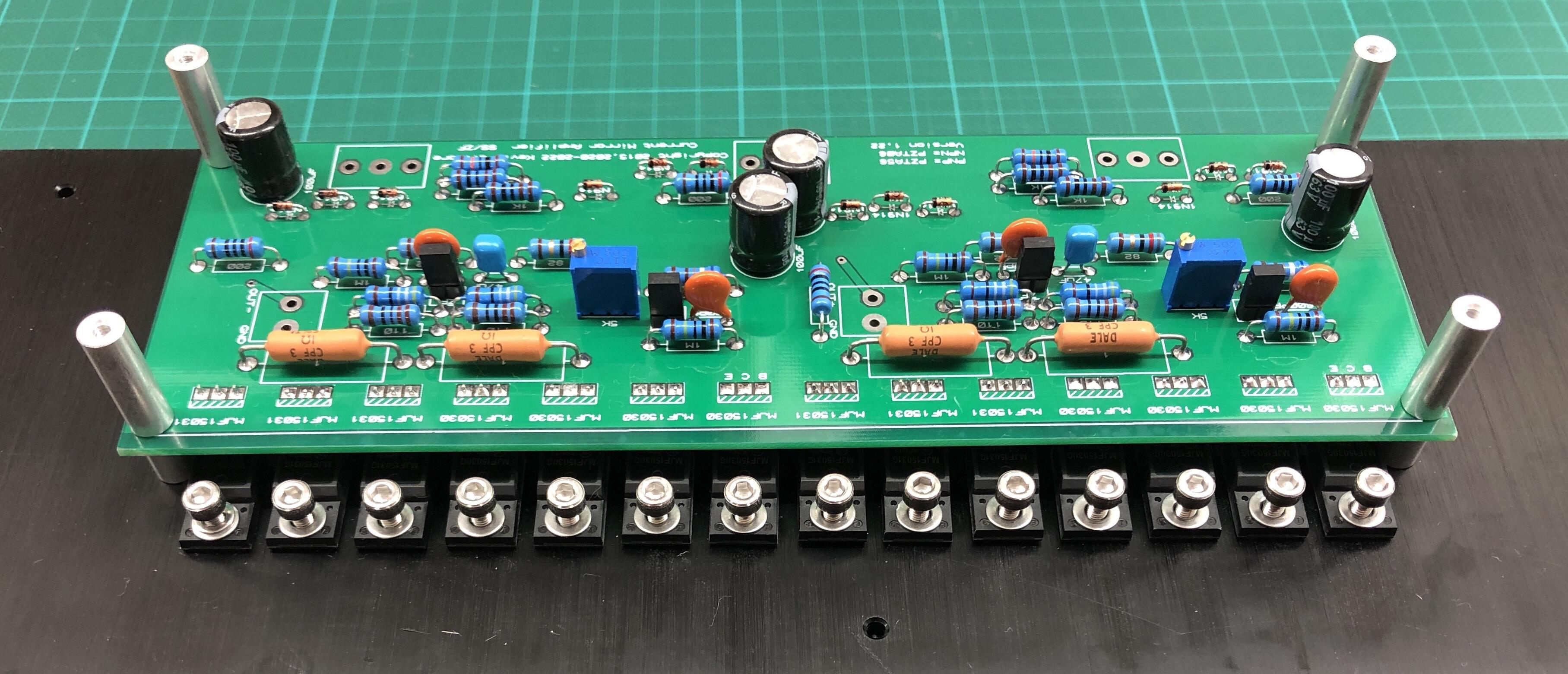
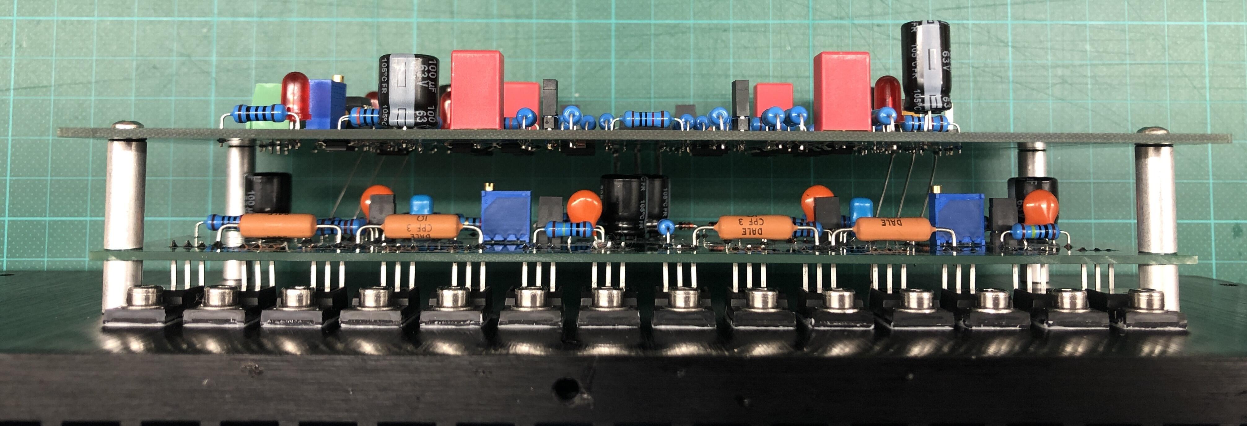
Looking nice! Are you going to bolt the pass transistors on the GRLVs to the heatsinks on the side of the case? They will need some cooling. First powering and adjusting the amp should be without the OPAs, so you can take them out for now. For the CFA3, I would advise to consider the headphone protector as well, which is pretty much a must for dynamic cans. It connects to Vcc+ of the amp and makes its own 12v out of a 7812 which is 1A and if you use a couple of low signal switching relays on the inputs, you can tap into it without the need for another transformer and voltages in the PSU.
-
Using rounded button head would be classic. If not you might pot the transformer into a transformer case like this and then mount it using 4 smaller screws, which might be then countersink. You can then easily rise the transformer as well.
-
For isolation I would use Aavid insulators, mostly ceramics if there is enough clearance, Aavid PPS shoulder washers and stainless steel mounting hardware tightened to 0.8Nm (M3 or #4-40 allen head screws). The Aavid insulators and shoulder washers are available in different sizes, depending on transistor packaging and size. I am attaching an ONsemi paper as well including mounting considerations for power transistors. For grounding follow this scheme, which shows pretty much the most complex case of a two box design, amp with a separate PSU chassis. Pic shows single ended amps, balanced would be slightly different as the signal do not touch ground, the amp chassis would change so that the inverted signal (cold, pin 3) would go to a second amplifier board instead to ground. Overall idea should be pretty clear however. Mounting Considerations - AN1040-D.PDF
-
Uff... Mouser delivered today only 4 from 6 backordered C2M1000170D, so I guess my Carbon boards are going to wait more months before first power on. I even have the LSK389's stuffed in there.
-
Like magic 🙂 Nice pics and congrats, looking good!
-
and now for something completely different part 3
audiostar replied to kevin gilmore's topic in Do It Yourself
On a side not here, cooling effect is bigger if sands are put on the lower end of the sink. As heat travels up, sink real estate gets used more effectively. -
and now for something completely different part 3
audiostar replied to kevin gilmore's topic in Do It Yourself
So, I am good with my four OPA445. Thanks, Kevin for confirming.
-
and now for something completely different part 3
audiostar replied to kevin gilmore's topic in Do It Yourself
I was checking old messages in the thread and found this. As I am running 30V dual GRLVs (with the new split boards), do I need to change from standard OPA445 to OPA551? Looks like... still not powered on for the first time. Looking through the specs, the OPA445 goes indeed up to 45V, confused. -
and now for something completely different part 3
audiostar replied to kevin gilmore's topic in Do It Yourself
Thanks, guys! I am looking for something that is not too long and does not stick out too much of the IC socket. Also most of the pins I got are square. -
and now for something completely different part 3
audiostar replied to kevin gilmore's topic in Do It Yourself
Thanks, Pars! Which pins are you using on the lower side, that go into the 14-pin socket, do you have the p/n handy? Thx -
Where would you put that, there is virtually no space left inside the box 🙂 Everything looks very nice so far, congratulations. Btw, I am using the same WAGO connectors, they very handy for quickly connecting multiple wires together during tests. Can even put 2mm test leads inside.
-
Check as well Keystone 5005 and 5006 if you need a test point with a hook attachment. Mouser p/n 534-5005 and 534-5006. Available in different sizes as well.
-
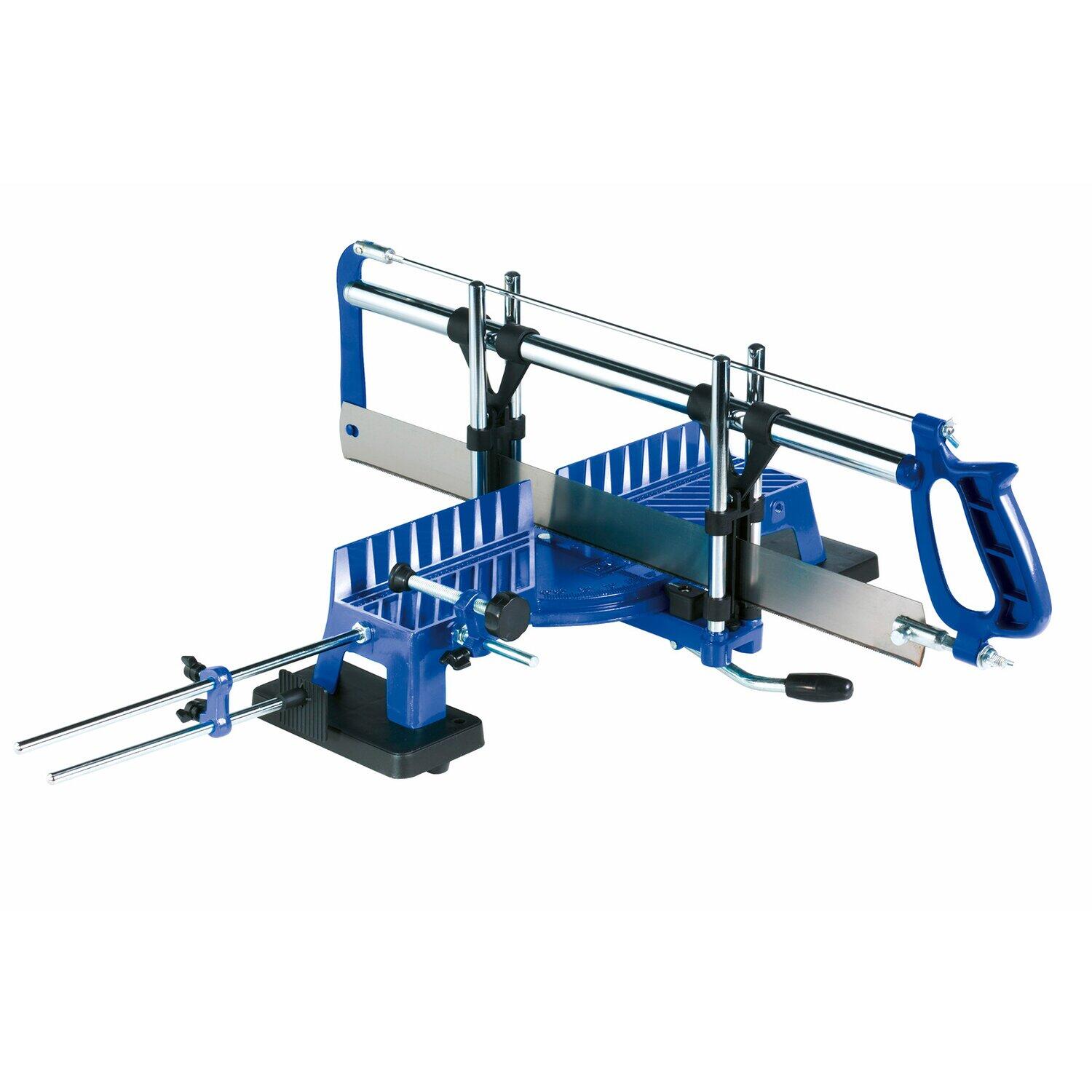
Hey Pars, these are Mill-Max p/n 4275-0-00-80-00-00-08-0. There are different sizes available. For bigger holes check Mill-Max p/n 4357-0-00-15-00-00-03-0, take a look at the catalog, there lots of options. Something like this will cut you perfect right angles, cost around $20 or so. You can then make a wooden base for it (attach instead of the black plastic parts) and clamp it to a table to make it rock solid.
-
Must be some difference in the components somewhere between both channels. I would do a diode test on all the sands and check that all resistors have been soldered where they should be (if not measured one by one prior to soldering).
-
Yeah, 2nd violin in the right corner of the stage will get shifted 1.5° to the center and this is no good 🙂
-
I have those already at max available rating. Would need a new transformer only. But in general yes, don't forget to check the caps. Thanks for your insight! You are right on the very small difference and hearing that is different animal than measuring it.
-
Hey Kevin, from all the alternatives, which would be your choice? Just swap the resistor, try to put in the ttc004, or swap transformer and go with 450 instead of 400V PSU?
.gif.4de1014ed1f09cc504521ea05cf59995.gif)