audiostar
-
Posts
310 -
Joined
-
Last visited
Content Type
Profiles
Forums
Events
Everything posted by audiostar
-
Thanks. Need either to change the rod to 6.35mm (1/4") diameter or the panel bearing to 6mm. Can't find a 1/4" rod around either...
-
Anyone knows of a metric panel bearing like this one from Keystone? Need it for a 6mm rod instead of 1/4". Small difference but enough for a 6mm rod to wobble in the Keystone 1705.
-
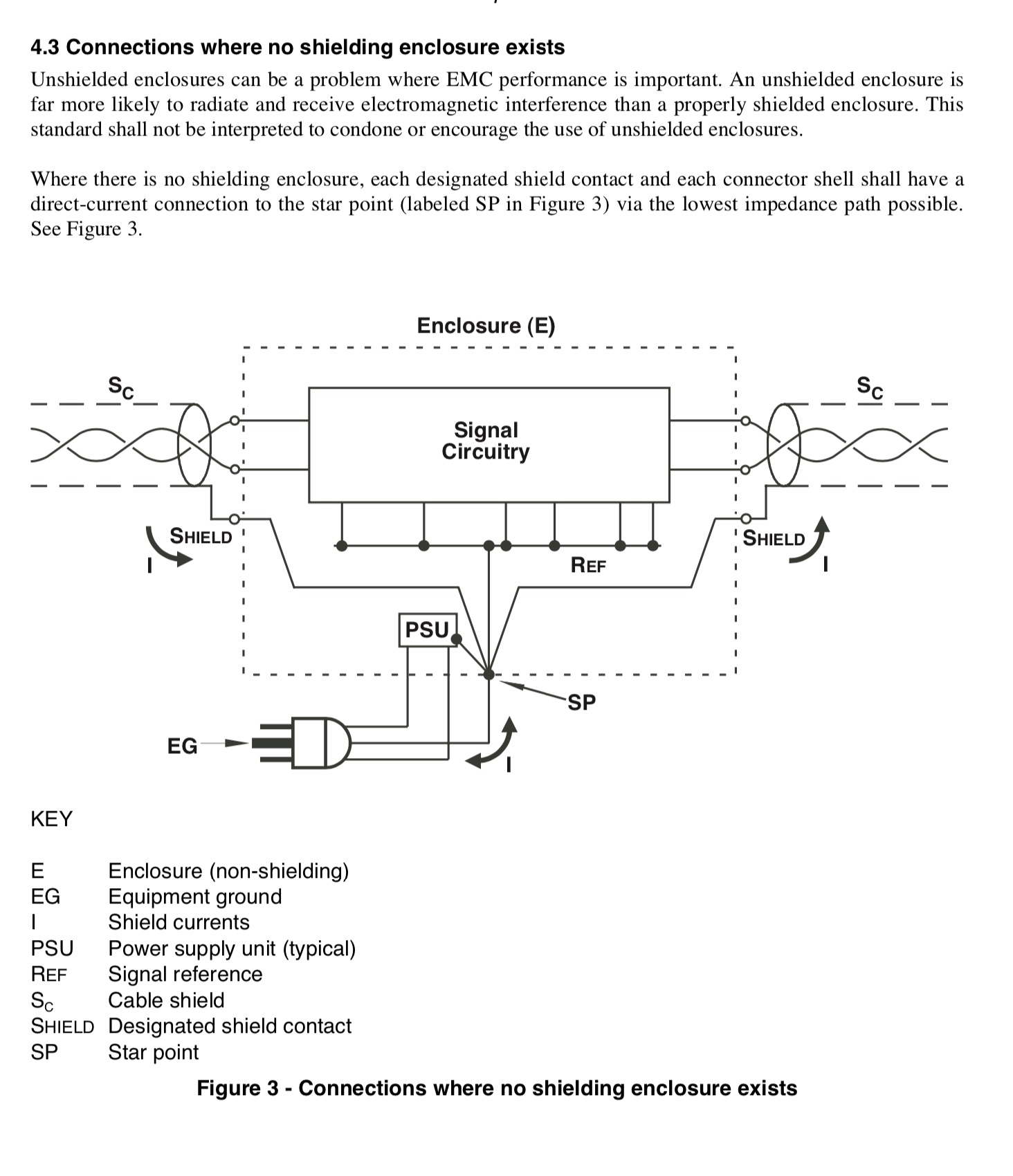
A differential signal doesn't need to reference ground at all. This is not a misconception. There is also a difference between a fully balanced device or source (4 channels for stereo), which I talk about and a single ended source (2 channels referencing ground for stereo) with only a differential output added to that, which you probably refer to (transformer isolation?) Of course you could go to the SP directly (a must with unshielded enclosures). Does it matter in a small metal box? Probably not much if everything else is right. But yes, you could do that. Pin 1 is not left floating, where do you see this? It connects either to a metal shielding enclosure and goes then to SP or directly to SP in a wooden box. Period. But where it doesn't connect to is directly to circuit ground. Here is the pic for unshielded enclosures:

-
The shell and pin 1 are (mostly) joined in the XLR connector (cable side). Some leave the shell unconnected but then those cables can not be extended as the shield gets broken. You could use in the cable connector shell a 100pF cap between both as does Neutrik in their EMC connectors to satisfy kind of all conditions. Otherwise: get to know your cables and your devices. Yes, with XLR jacks (chassis side) with separate pin 1 and ground connections you can keep things easily "configurable" with a jumper inside the unit.
-
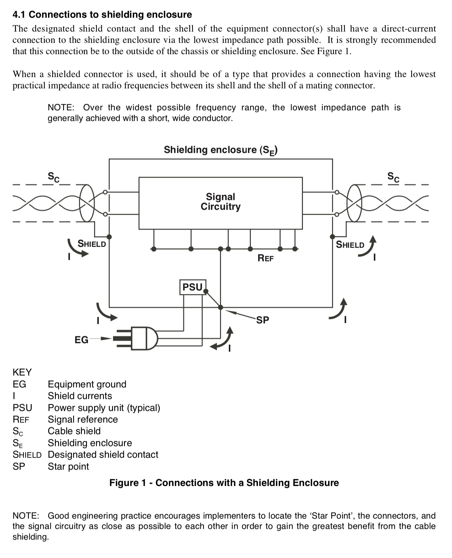
A differential signal doesn't need circuit ground as return path and the XLR/RCA adapters connect cold pin 3 to RCA signal ground while the RCA jacks (chassis side) keep ground isolated from the chassis. So all good, in case of proper implementation of course. Here is a pic from the AES paper on grounding for a metal (shielding) enclosure. One box design is shown, but the idea should be clear. Edit: Look for Neutrik (chassis side) jacks with complete metal ring (B-series) or metal case (D/DL-series) for the best possible shielding/mating with a metal enclosure. A/AA-series use a plastic case and make a single point only connection (via the screw) to the metal enclosure.
-
Yes, a source truly differential. You could completely untie pin 1 on both ends and only use a drilled wire for hot/cold pin 2 and 3.
-
Sounds good. IEC earth = PE, protective earth
-
Also true, and they all do it wrong. Rane and AES talk about this. Benchmark does it right, they even have a paper about this. Neutrik introduced the EMC XLR connectors to cure this to some extent. Best of course would be to properly use and interconnect the various grounds.
-
True. It may get audible in large installations and studios with equipment powered off different outlets on separate phases, different earthing and zero potentials, etc. Doesn't matter in a home with 2 or 3 boxes, all powered off the same wall outlet.
-
I am not connecting PE (which is actually chassis ground at this point) to circuit ground in the amp's case. pin 1 in the amp's case is tied to the chassis only (but not circuit ground) and goes then via the chassis wire to the PSU box and there it gets connected to PE and circuit ground only at the star point. This is described in one of AES documents, I have posted a link to somewhere earlier.
-
Yes, using 0.8Nm as you as well without issues. Looks like the above is missing a 0. But still a bit above the spec Craig posted. Probably +0.13Nm isn't a dealbreaker if everything else is right.
-
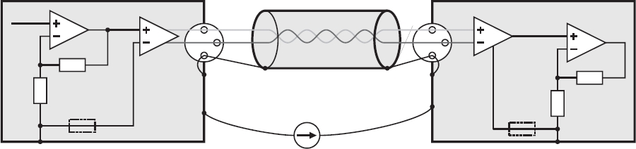
Yes, right, the pic above shows a source component and another component probably with integrated supplies. With a separated PSU, chassis ground and circuit ground are carried separately between PSU and amp and they connect to each other only in the PSU's case. Doesn't matter if T2 or any other class A power amp like the XS300.
-
Exactly as I wrote above. Meanwhile Kevin uses a 10R resistor between circuit ground and PE ground (like on newer GRLVs), same as Krell. Nelson Pass uses a thermistor and the IEC recommends a real ground break circuit consisting of a HF power cap, power resistor and a rectifier (inverse parallel coupled power diodes). The idea is that this network must survive longer that it takes the mains fuse to rupture and for the arc to extinguish. This is also described on Rod Elliott pages in more detail. The essence thing is to connect both PE and circuit grounds in the PSU box only at the star point and have both grounds run separately to the amp's chassis. Regarding pin 1 grounding which in this context plays a role as well and was asked above, here is a pic. It goes to the amps chassis and then to the PSU chassis (remember separated chassis ground wire run) and then to PE and is (in a differential amp setup) used with metal chassis basically for shielding only. In order to satisfy the various environments and wildly used grounding schemes and avoid loops, there is a new series of expensive Neutrik EMC XLR connectors using a cap between the connector's shell and pin 1. Here is a good read up on this.
-
And this is exactly how you don't do it. You pass both signal and PE grounds (separately) to the amp's chassis. PE connects there to the chassis only. Signal ground is obvious. And absolutely no other connections between both. In the PSU case you connect to the chassis (near the mains power entry): 1. PE ground, 2. transformer shield (if any) and 3. signal ground (best through a circuit breaker, at least a 10 ohm resistor) in a star manner. And this is the only connection where PE ground connects to signal ground (better called circuit ground as a differential signal doesn't use ground).
-
and now for something completely different part 3
audiostar replied to kevin gilmore's topic in Do It Yourself
To quote Nelson Pass: As a rule of thumb, the output devices should not be operated at more than about half their maximum rating, and generally the case temperature needs to be under 100 deg C. For most amplifiers this means a heat sink temperature of about 50 to 55 deg C., which is the temperature that you can put your hand on for about 10 seconds. -
Kerry Design mini GRHV\GRLV and JoaMat mini T2 Group Buy
audiostar replied to mwl168's topic in Do It Yourself
Thanks, Pars. -
Kerry Design mini GRHV\GRLV and JoaMat mini T2 Group Buy
audiostar replied to mwl168's topic in Do It Yourself
Any good substitute for the shottky diodes MBRA140T3G in D3,D4,D5,D6? I could find this one: https://www.mouser.com/ProductDetail/750-CDBA140-G, it is in a different package but pretty much same length. Forward voltage 500mV instead of 710mV for the MBRA140T3G. -
Mouser has a couple of MJW21193G, grab them while they last.
-
Was just looking for a version of the Amphenol MIL connector with crimp contacts and indeed there is. The widely known solder-type connectors are PT02A-14-15S for the socket type (chassis side), as used in the PSU PT02A-14-15P for the pin type (chassis side), as used in the amp the equivalent but crimp type box-mounting receptacles would be PT02SE-14-15S for the socket type (chassis side) PT02SE-14-15P for the pin type (chassis side) 20 AWG crimp pins: M39029/31-240 20 AWG crimp sockets: M39029/32-259 16 AWG crimp pins: M39029/31-228 16 AWG crimp sockets: M39029/32-247 Straight plugs for the cable side are available in crimp as well. Just replace the PT06A-xx-xxx with PT06SE-xx-xxx Full specs here.
-
Now, going to order some transformers 🙂 Is there anything speaking against using the following secondaries with this PSU? 320Vac @ 0.18A -> 400Vdc 365Vac @ 0.18A -> -460Vdc For the +220Vdc I'll use a separate GRHV, like the kgsshvpssicfetsinglenewright but without the Bias portion on it.
-
and now for something completely different part 3
audiostar replied to kevin gilmore's topic in Do It Yourself
Indeed, you are absolutely right JoaMat. I was looking earlier but couldn't find anything. Thanks again! -
and now for something completely different part 3
audiostar replied to kevin gilmore's topic in Do It Yourself
Anyone has a source for this type of side panels? They are used by Modushop as well, but unfortunately not selling as spare parts outside of a complete case set! -
and now for something completely different part 3
audiostar replied to kevin gilmore's topic in Do It Yourself
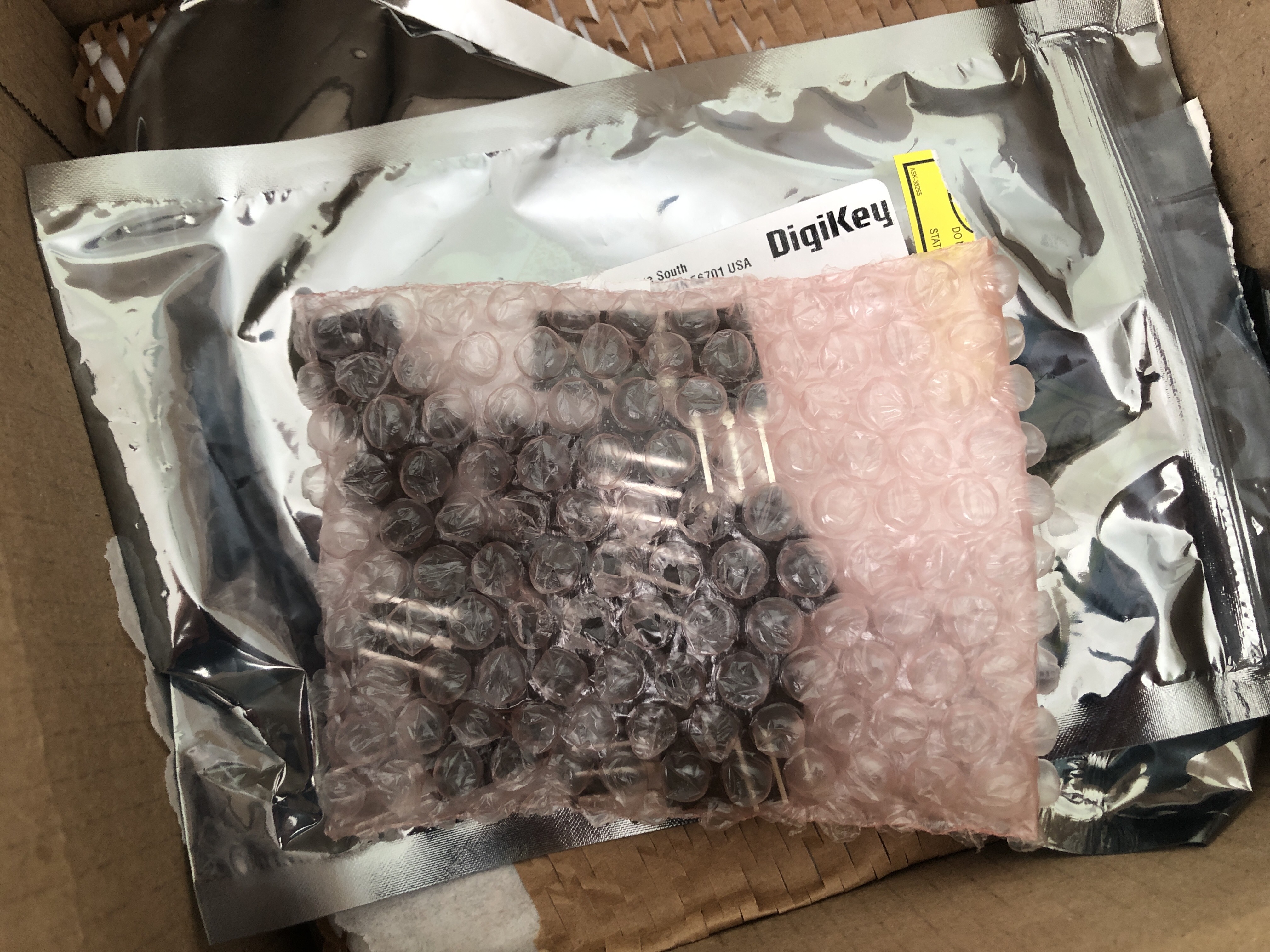
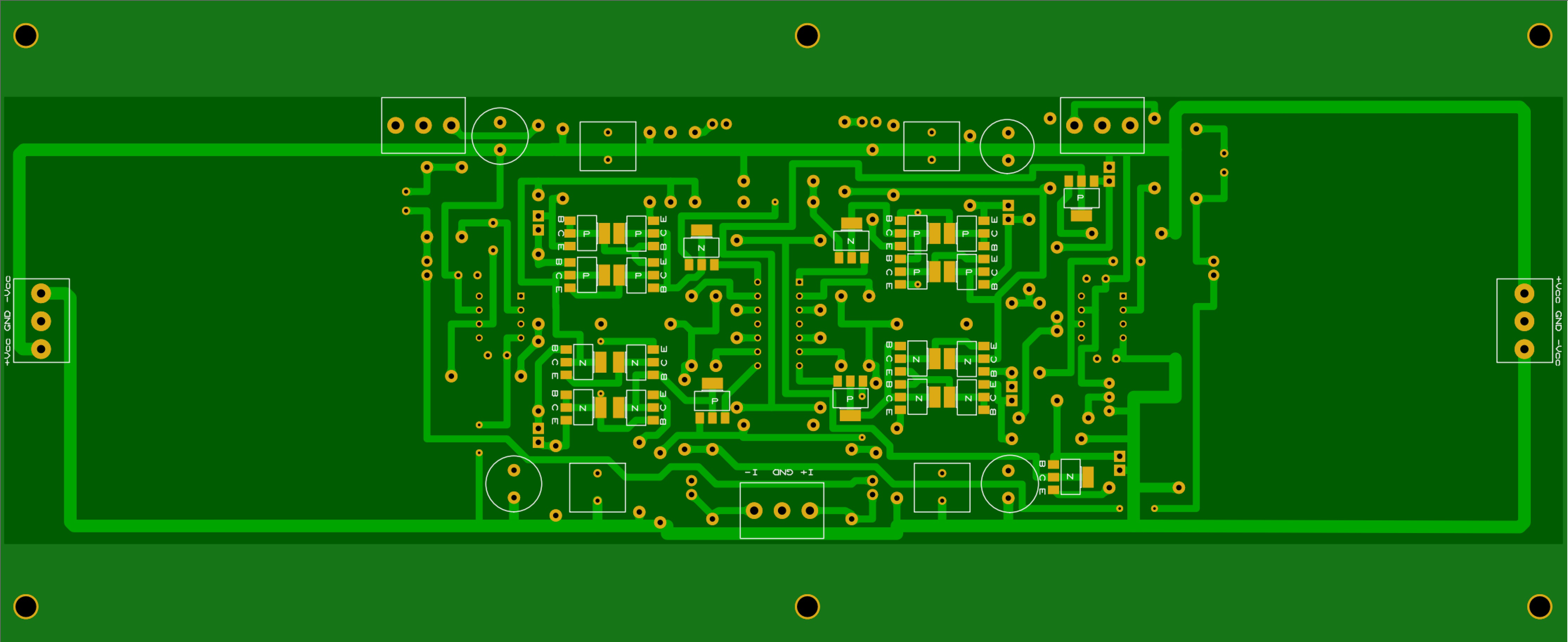
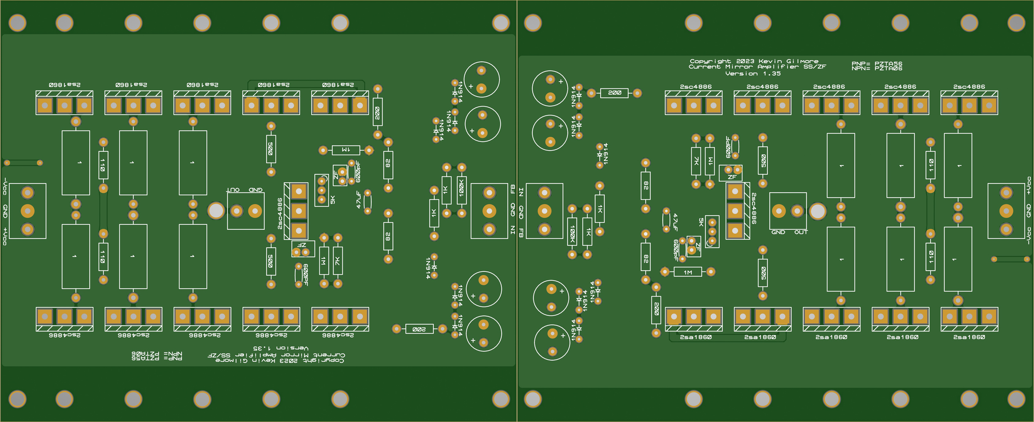
Look what UPS just delivered from Digikey... And of course something is missing (3x 2sa1860)!
-
I bet JoaMat is already changing some caps 🙂
-
and now for something completely different part 3
audiostar replied to kevin gilmore's topic in Do It Yourself
Something like this: Both 285.6 x 116.8 mm