audiostar
-
Posts
310 -
Joined
-
Last visited
Content Type
Profiles
Forums
Events
Everything posted by audiostar
-
.
-
If I were to build the T2 again, I would put as much (lower hight) components as possible on the top side of the board for better cooling, at least all the 0.5w Xicon resistors, in addition to the LEDs. Very nice work on the modular batteries. Surely the way to go nowadays.
-
The light bulb protects from any shorts, limits the current as well. The Variac would not really protect from shorts, but it allows for testing 115 volts nicely (I have a step down transformer for US mains).
-
Me neither (using the incandescent light bulb tester) but James is a Variac specialist 🙂
-
Yep, these cases are nice! I use the same heatsinks, Ali has all sizes available. Milling then the front/back panels need to be done anyway and 2x identical top/bottom covers is pretty straight forward. Complete cases with those heatsinks are available as well. Here one with the 2U heatsink though.
-
Megatron Electrostatic Headphone Amplifier
audiostar replied to kevin gilmore's topic in Do It Yourself
Thanks, JoeMat and a Happy New Year as well! So, you carry circuit ground through both umbilicals which you connect separately to both channels in the amp's chassis). Safety Earth, you carry through both umbilicals as well and connect both to a single point in the amp's chassis? Bias line you split in the PSU chassis and carry through both umbilicals as well, but connect in the amp's chassis only one of them to the actual Bias output? In the power supply chassis you tie ground of all PSUs together and connect through a circuit breaker (or not, or simple 10R, etc) to the chassis itself & Safety Earth coming off 1) the IEC mains connector and 2) both umbilicals off the amp's chassis. -
Hey Alex, that looks fantastic ... and a Happy New as well, cheers!
-
Kevin is talking about his amplifier, the DIY T2. Of course you can design another one and change everything.
-
Hey Alex, I can't access the attachment.
-
Hey Alex, that looks really nice. Btw, why did you decided to have a separate trafo on the headphone protector board? Or is it temporary only? Cheers
-
and now for something completely different part 3
audiostar replied to kevin gilmore's topic in Do It Yourself
This is why I use the original values from Kevin. -
and now for something completely different part 3
audiostar replied to kevin gilmore's topic in Do It Yourself
Hi Pars, the latest revision v1.2 THD boards say BC546B and BC556B on them. Regarding to the ZF and feedback resistor change it is for both around 2x, so 50k instead of 25k and 4.2k instead or 1.9k, basically what Paradoxper used. Important is that both modes match in volume - you may scope with 1kHz and match the 4.2k so that you get same volume in ZF-mode as in feedbak mode. This being said, I am still using 25k for feedback and 1.9k for ZF and only using the amp in ZF-mode. As well as using the B-version sands from onsemi. -
Megatron Electrostatic Headphone Amplifier
audiostar replied to kevin gilmore's topic in Do It Yourself
JoaMat, question on umbilicals (or better the connections though both) - are those absolutely identical for both channels? Probably shouldn't, as Safety Earth (that must connect both Amp/PSU cases to Earth in the PSU case and to circuit/star ground as well) should be carried through one only, right, in order to avoid loops. What about circuit ground, as lately in the Stax connector both left and right channel ground connect together, so if ground is carried through both Umbilicals, this would introduce a loop as well? -
Megatron Electrostatic Headphone Amplifier
audiostar replied to kevin gilmore's topic in Do It Yourself
Hey JoaMat, very nice 🙂 What is that transistor storage system you use? -
Just put more flux and all is good 🙂 Alex, nice components selection!
-
He has has been known for selling fakes. Try to return those.
-
and now for something completely different part 3
audiostar replied to kevin gilmore's topic in Do It Yourself
I see you have switched here to 50k feedback resistors and 4.2k ZF-resistors. The 20pF cap alongside the feedback resistor you left. Like the new name much more as well, Current Mirror Amplifier! -
and now for something completely different part 3
audiostar replied to kevin gilmore's topic in Do It Yourself
Kevin, this looks beautiful! What are the dimensions of that PCB, still the same? -
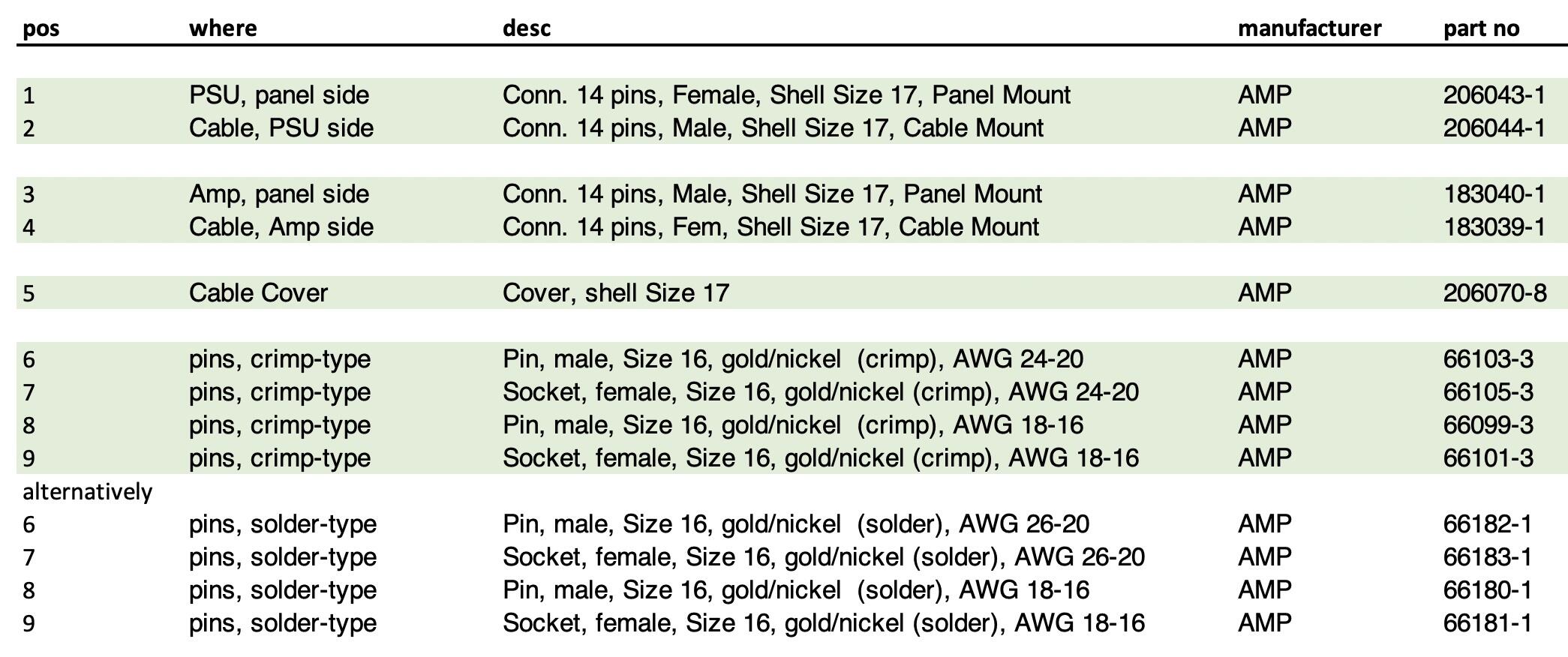
I am using the same connector system, it indeed is a nice one. Panel side connector can be mounted inside the panel on up to 3mm thick panels as the plug does not screw all the way down.

-
Looks really great, appreciated your great work! You have a mouser BOM that you can share a link to as well?
-
goldenreference high voltage power supply (GRHV)
audiostar replied to Pars's topic in Do It Yourself
John, thanks for reporting! Did you used it in the amp section as well or only in the GRHV? I have the feeling that the GRHV alone could be happy with it, but probably not the Carbon. -
goldenreference high voltage power supply (GRHV)
audiostar replied to Pars's topic in Do It Yourself
Any recommendation for connecting LED for power on/off indication to a GRHV-only based CFAE amp? A possibility would be to connect a 3V LED to 230V AC through a 1N4007 and a 56k resistor. I don't like using those power switches with integrated lights. Any other or better ideas? The CFAE only has a GRHV and 230v mains, unfortunately no LV. -
and now for something completely different part 3
audiostar replied to kevin gilmore's topic in Do It Yourself
Hi all, anyone have a p/n for the 600pF cap optionally used in the CFA3? The closest I can found is a 620pF MLCC Kemet, but no 600pF... -
Shield stays connected to the chassis only. Ground is pin 1. I use Neutrik's that have separate shield/chassis connection from ground and chassis goes back to the PSU where only there chassis connects to circuit ground and mains ground (in a star manner). So, in your example for the input I would only switch pin 2 and 3 (and not switch ground, nor shield) with a DPDT relay best, something like a a Kemet EC2-12NU (one per channel), located near the inputs on the back of the amp. A front located SPDT switch will only toggle the relays. The output I probably would not switch at all, but depending on the subsequent device (power on/off status) it will be the one or the another (or both, if you make sure you can use both outputs at the same time). Ofc, you can have the same switching for the output as on the inputs, one EC2-12NU per channel and switched by a front located simple SPDT switch. As you prefer. The above Kemet's are for 12V, check the voltage in your device or use MC78/79 type of voltage regulators or change relays to 5V,... 24V to suit your needs. Omron G6A-234P-ST-US relays might be used as well.
-
goldenreference high voltage power supply (GRHV)
audiostar replied to Pars's topic in Do It Yourself
I am using the C3M0350120D as a replacement part for the C2M1000170D in the GRHV in my CFA Electrostatic without any issues. But this part seems to be unavailable now as well. Remarkable how one needs to wait a year for parts now.