audiostar
-
Posts
310 -
Joined
-
Last visited
Content Type
Profiles
Forums
Events
Everything posted by audiostar
-
Great finding and thank you for reporting! From what I can see the majority are running their Carbons with 400V PSUs..
-
and now for something completely different part 3
audiostar replied to kevin gilmore's topic in Do It Yourself
Thanks, Kevin, found it. The pinout for the 2SA1349/2SC3381 do not line up with 2SJ109/2SK389 though, despite being the same package. Will make a new one and post it. Great, Pars. Could you please post here. Thanks mucho! -
and now for something completely different part 3
audiostar replied to kevin gilmore's topic in Do It Yourself
Has anyone any adapter boards left or gerbers for using 2SJ109/2SK389 in the 14-pin JFET socket? I am sure I was looking somewhere at these, unfortunately can't find anymore. -
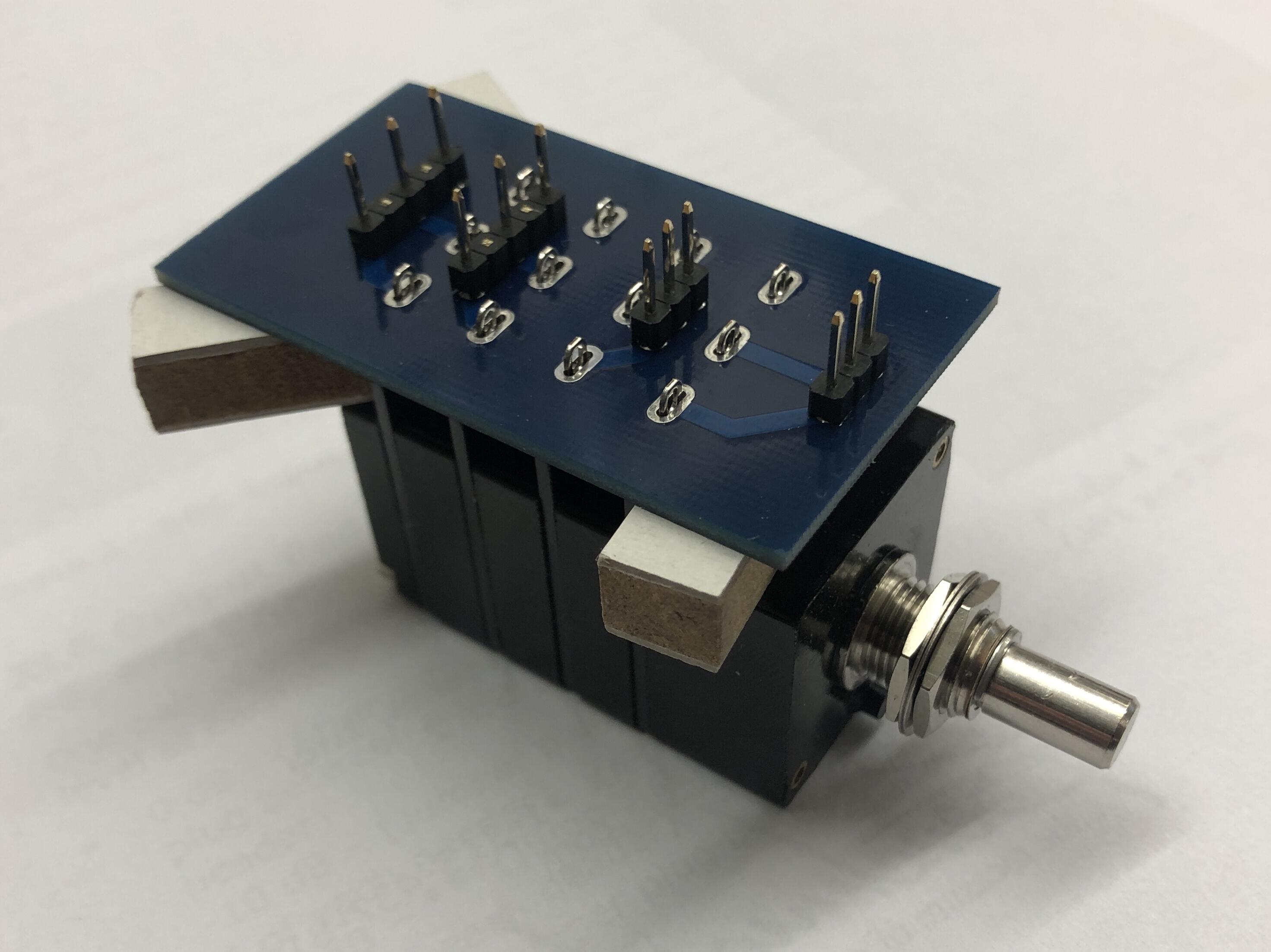
That's nice. Which pot do you use and is it log or linear tapper, does that matter? Looks like a single channel pot will do. I assume you completely power off the amp in between usage, so no standby trafos involved? Looking through the archives the attenuatorsmtv42flipground7 seems to be the latest version of the boards.
-
Hey Beefy, nice you got it working, congratulations! I was playing with the idea of using those boards myself. Just curious is the volume level remembered after power off and then subsequential power on?
-
and now for something completely different part 3
audiostar replied to kevin gilmore's topic in Do It Yourself
@kevin gilmore would there be any benefit in using low inductance resistors like Caddock or Fukushima MPC74 for the 1 ohm resistors? -
and now for something completely different part 3
audiostar replied to kevin gilmore's topic in Do It Yourself
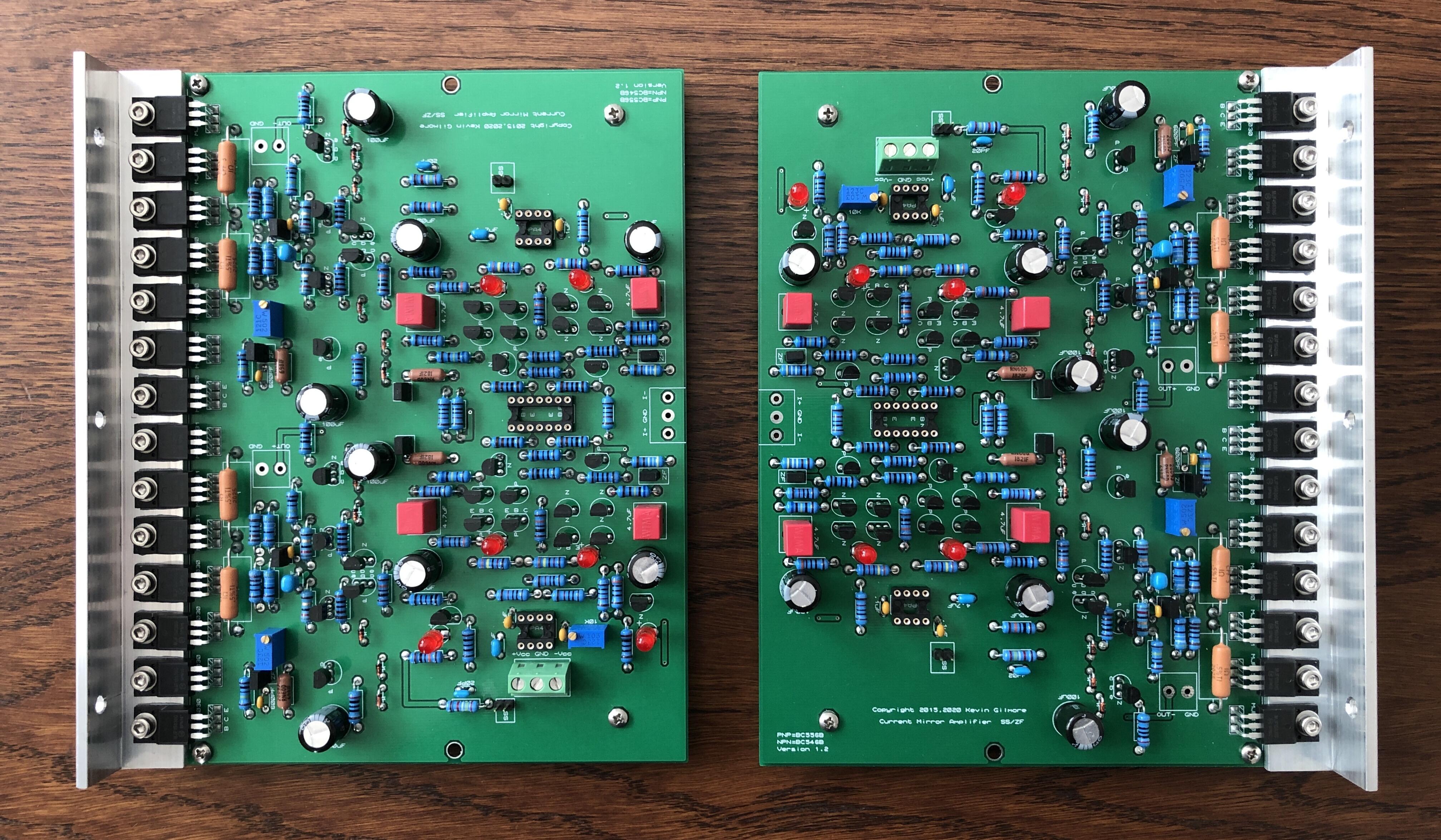
To be honest the only reason for me moving to split boards is pure cosmetics, because I can fit them better in my case which is taller but same 32cm width as my external dual GRLV PSU. If I was going to use a standard 43cm case I would not switch, no reason to. Originally I planned to use the wider boards in the same case with the left board on top and upside down and right board on bottom, leaving space in the middle for the rod coming from the back where the input selector board would be holding the pot as well. But this is not as nice as using the split boards. I would not move everything, probably only the MJF devices, the Bourns trimpots, some caps and maybe the 1R CMF resistors. -
and now for something completely different part 3
audiostar replied to kevin gilmore's topic in Do It Yourself
Prior I start desoldering any components from my other boards, I thought I'll ask if anyone might need two fully populated (except Opamps and JFETs) wider boards. Not trying to make any profit, will sell at BOM cost, DM me if interested. Those have never been powered up, build to specs, MJF devices tightened to 0.8Nm using stainless steel hardware, 105°C Panasonic FR electrolytics and WIMA/Kemet/Murata caps used as well as Bourns 3296W trimpots and Mill-Max IC sockets. All BC556B/BC546B onsemi devices were selected from 100 and are matched to Idsss.
-
and now for something completely different part 3
audiostar replied to kevin gilmore's topic in Do It Yourself
Look what the cat just dragged in 🙂
-
The modern version would be WAGO 221-2411. They can be stacked together (optionally if you want) by WAGO 221-2504.
-
To circumvent this loop issue and to not sacrifice the dual mono nature of this amplifier, maybe the left Stax connector should be fed by the Bias from the left umbilical and the right Stax connector fed from the Bias coming from the right umbilical. Would be my solution to this.
-
Congratulations, Kerry and mucho success with your new venture!
-
and now for something completely different part 3
audiostar replied to kevin gilmore's topic in Do It Yourself
Hey Kerry, what is the Aeras e-stat amp? -
Looks very nice! The GRLV might make a better power supply, maybe something to upgrade later to.
-
and now for something completely different part 3
audiostar replied to kevin gilmore's topic in Do It Yourself
Wow, thanks Kevin - thats pretty! I wish I have waited for this but I already finished the regular cfa3 and casing it right now. Add a board for input selection in the back, the protector3 and a board holding the pot and phones connectors in the front and this makes up for an awesome amp. Could not resist, ordered boards... -
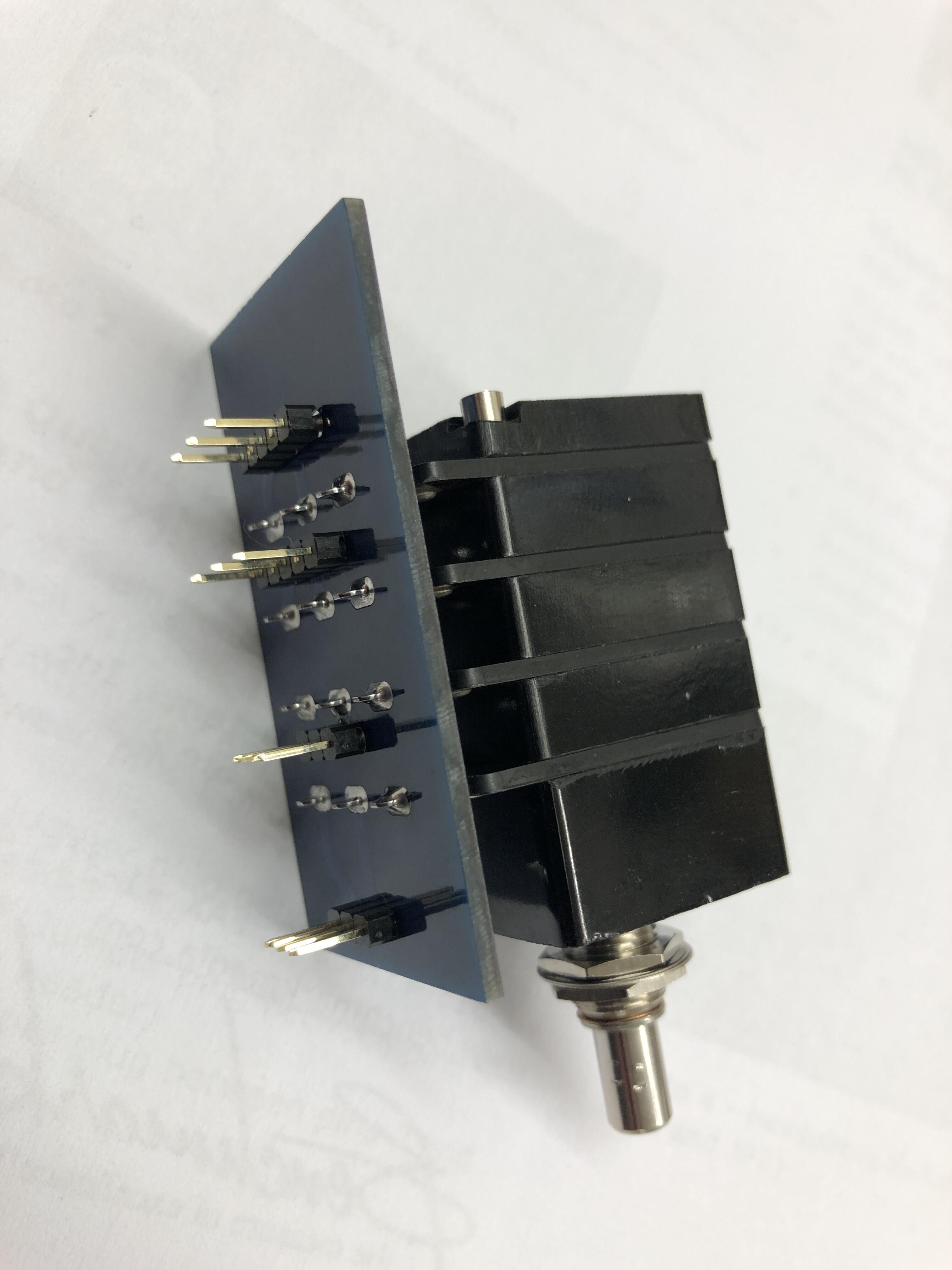
Made a mezzanine adapter board for the TKD 4CP-25xx pot on the original DIY T2 board from Kevin. Precisely adjusted the hight of the pot to board prior soldering. Worked out perfectly.
-
Hey Alex, how is your KSA-5 going?
-
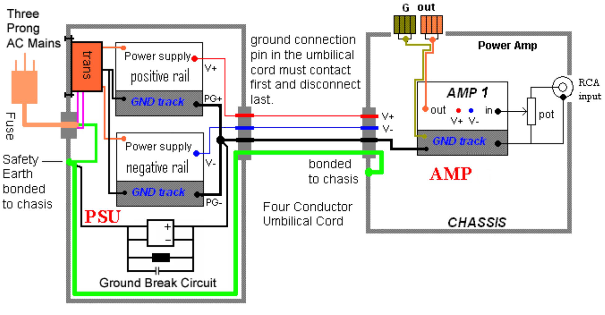
Here even the most complete case with an external power supply. GND and PE should make contact first and break last (in connectors between PSU and Amp case). Edit: The image below shows single ended amp though, Carbon being balanced one would connect the - to the 2nd amp half and not to ground, but that was not the original question.
-
This is what I have written in my first reply above, in detail... using 1) circuit breaker 2) a 10 ohm R or 3) directly. For the sake of this test it is not relevant. All signals GNDs together best in star.
-
Nice James, thanks! Will put a 10k TKD 4CP-2511 in my original T2 and see how it goes.
-
Anyone used the T2 with a 10k pot?
-
Hey James, personally I would prefer to wire each PSU and board GND to a single point, not making any PSU a "master". Much cleaner.
-
Transformer specs more than enough for a Carbon. The LV is way oversized if this is 500mA per 18V sec winding. PS: You can twist all AC lines. Includes the long + and - from pot to amp board inputs.
-
Again, this is not good. As I said above, connect ground of all PCB together and to the chassis. Best in a star config, saves wiring as well. He said above he is using split GRHV and the ground of one half goes to left amp board and the ground of 2nd half goes to right amp board with no connection in between.
-
This is no good! Connect all grounds (LV, HV+, HV-, all amp boards) together to a single (star) point. From there you connect to chassis (best is through a circuit breaker if not 2nd best is through a 10 ohm R, 3rd best is directly).