Kerry
-
Posts
2,292 -
Joined
-
Last visited
-
Days Won
12
Content Type
Profiles
Forums
Events
Everything posted by Kerry
-
Nice work! The output accuracy is also controlled by the resistors in the voltage divider, which are only 1% for the dale/xicon. For our purposes, this is not an issue.
-
I placed an order with them a few months ago. it did take a few days between responses but the order was processed and delivered just fine.
-
Thanks. I was just watching the eclipse. Very cool.
-
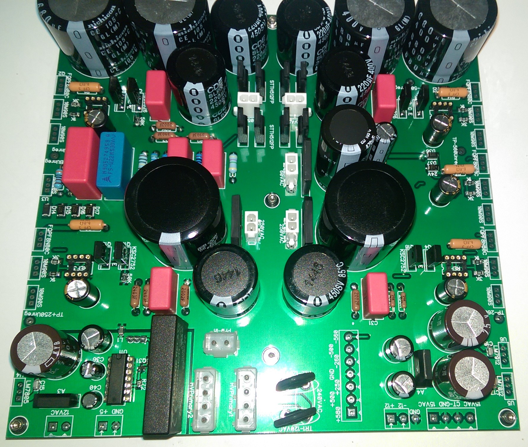
I think the trim pot is a good place to look. I remember Inu looking at them as well as some other members needing to replace them to clean up the noise. I think Inu did a full substitution with a fixed resistor at some point. It's been a while so I don't completely remember. For me, the noise was definitely coming from the resistors. I used PRP and ended up replacing with everything in the batteries with Xicon, which did the trick. Finicky thing these batteries. Speaking of trim pots, JoaMat, what trim pots are you using in your SMD battery above. I'm just laying out my new boards and I wanted to size them properly. Given that yours worked, I thought it would be a good source. Lastly, I finally got to testing my new PS. +/-500V, +250, -300, -60, +/-12V and 5V supplies. Everything checked out. One note is that the 47nF or .1uF bypassing the resistors going into the 20K resistors and feeding the error amp seem to increase any oscillations coming from the prior stage. I've taken them out for now. I'll post something about this in the carbon thread as well, since these new supplies are used there as well. I'm seeing noise levels under 6mV, but there is likely noise coming from my room that I'm seeing. Also, I'm seeing some random spikes at around 50mV. EDIT: I'm going to try adding an EMI filter at the input to see if it cleans this up.

-
That's awesome. My plan was to go SMD for the amp section, including the batteries. I was thinking of putting pads for both battery styles. what FET did you use?
-
Yeah, I thought he would just always be there. RIP.
-
I'm curious about current flow around the batteries. I wanted to ask what the voltages are across R1, R2, R3, R42, R58 & R59. Sounds like some dead transistors/LEDs for the current sources/sinks + something in the batteries as well.
-
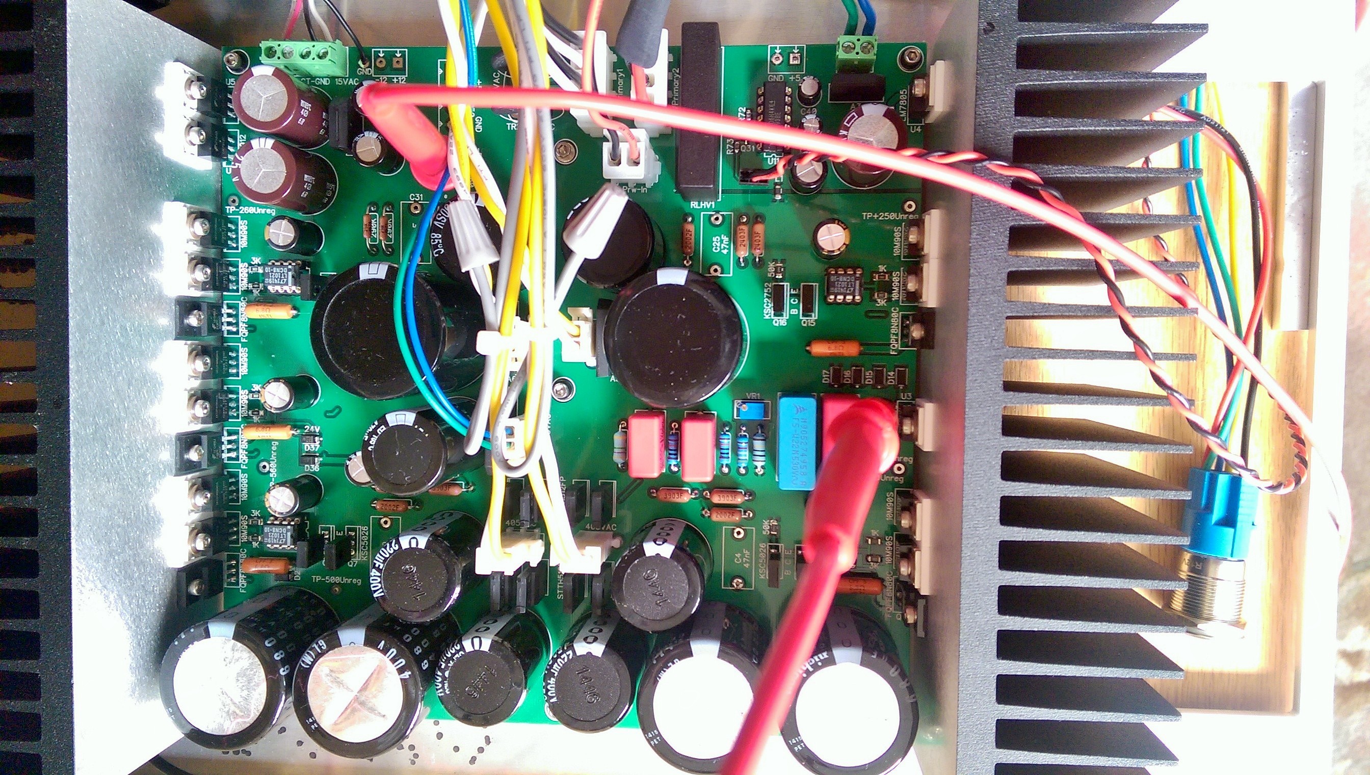
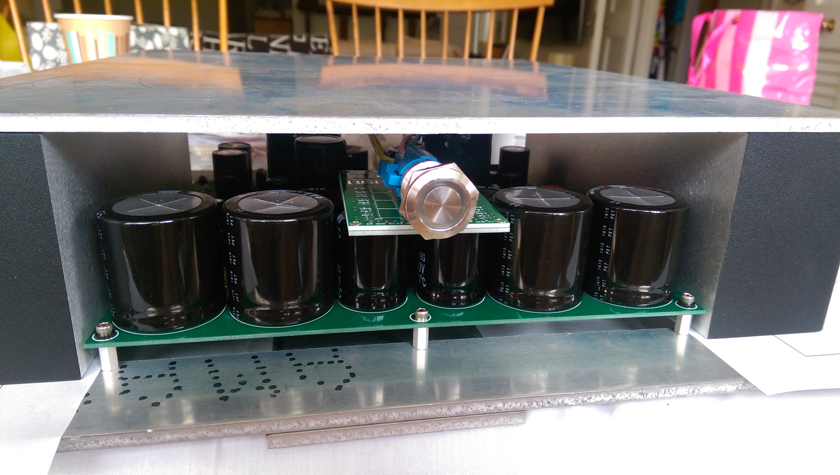
I wanted to mention that a few folks have been having issues with the power supply not supplying enough current on the -500V rail. Seems like setting the 30 ohm resistors to 20 ohms helps. The behavior is that if just one channel (either side) is connected then everything works perfectly, but if you connect both sides, then the rail sags and it's impossible to adjust the batteries correctly. If you're not having the issue, there is no reason to do this. I'm not sure if the amp is drawing a bit more or the current sources are providing a bit less than needed. In other news, I just got my PS together. I need to mount transistors to heatsinks, which I'll be working on today. I did test the relay driver and found a small issue for the LED output, but it was easily solved. I've got it mounted in a jig so I can easily solder the remaining transistors from the bottom. Here's some shots EDIT: I just wanted to add that I love working with the SMD parts and heat gun. I'd say I can move about four times faster when stuffing components.
-
^ Yes!
-
Interesting stuff. Thanks
-
I would put the dropout voltage around 12v and possibly less. For calculations you should use 20v. I also add ten percent to the overall voltage requirement to cover variances. transformers are a bit of a sliding scale of voltage base on the design parameters and actual current draw.
-
I will finalize my testing on the .4 version this coming week. I think from there, someone just needs to compare the .4 version to the current version to ensure there are no issues. The next steps are to work with the manufacturer to get some test boards made. We will need to provide sample boards to them for the 10k and 50k versions. I don't mind helping out here and building these samples. Then we can make the final run of boards and assemblies.
-

Closed - KGSSHV Carbon and GoldenReference HV PS Group Buy
Kerry replied to mwl168's topic in Do It Yourself
^ This. Thank you! -
Wow. That's fantastic. Where were you able to source the heat sinks? great work!
-
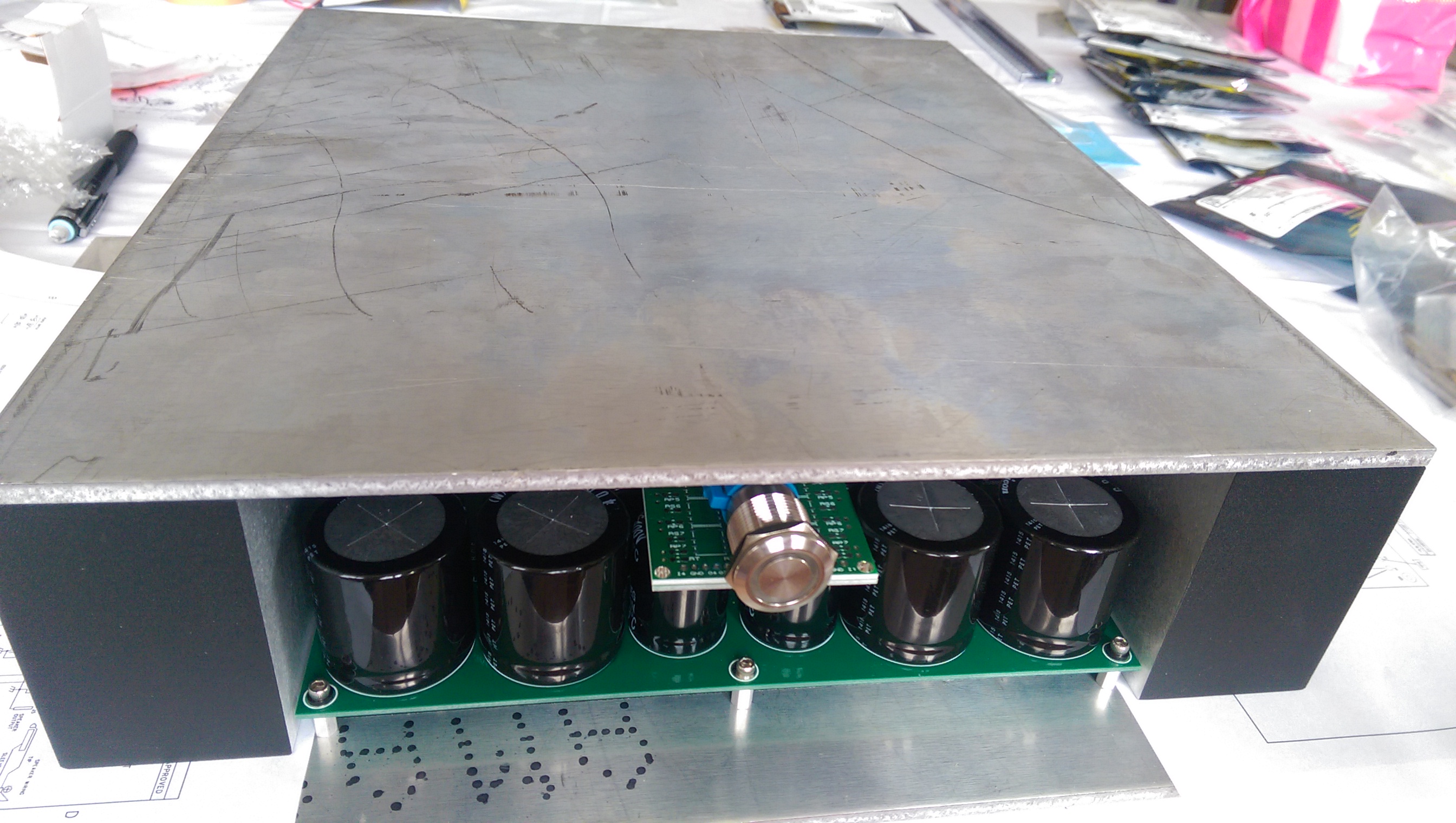
Yes. I wanted to save some width. In the end, I think it's less work not having to mill the angle brackets and just tap the heat sinks. It's only a few more taps than mounting the angle brackets. Also, my metal work got very good from building a couple of mills where precision is critical. Definitely not for everyone. I'm going to start milling the bottom plate and tapping the heat sinks this weekend. PS I can't show the bottom of the PS since I saved the PS to the wrong format and ultimately lost it. EDIT: I have roughly the same space available as the original T2 Chassis for the transformers since the heat sinks don't go all the way to the back of the chassis. They would not otherwise have fit.
-
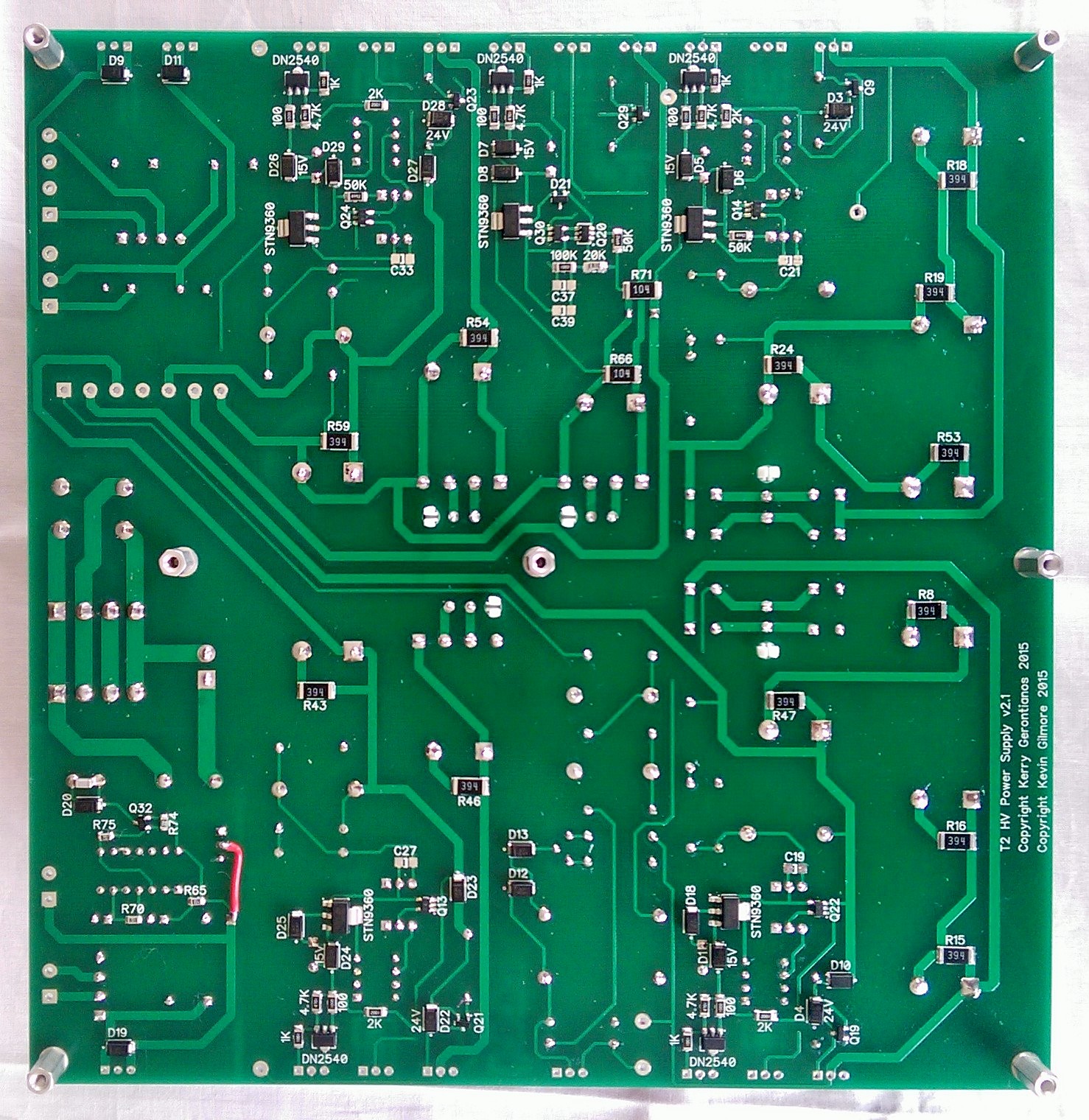
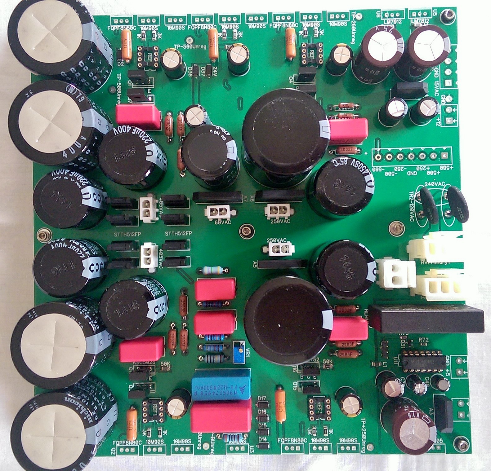
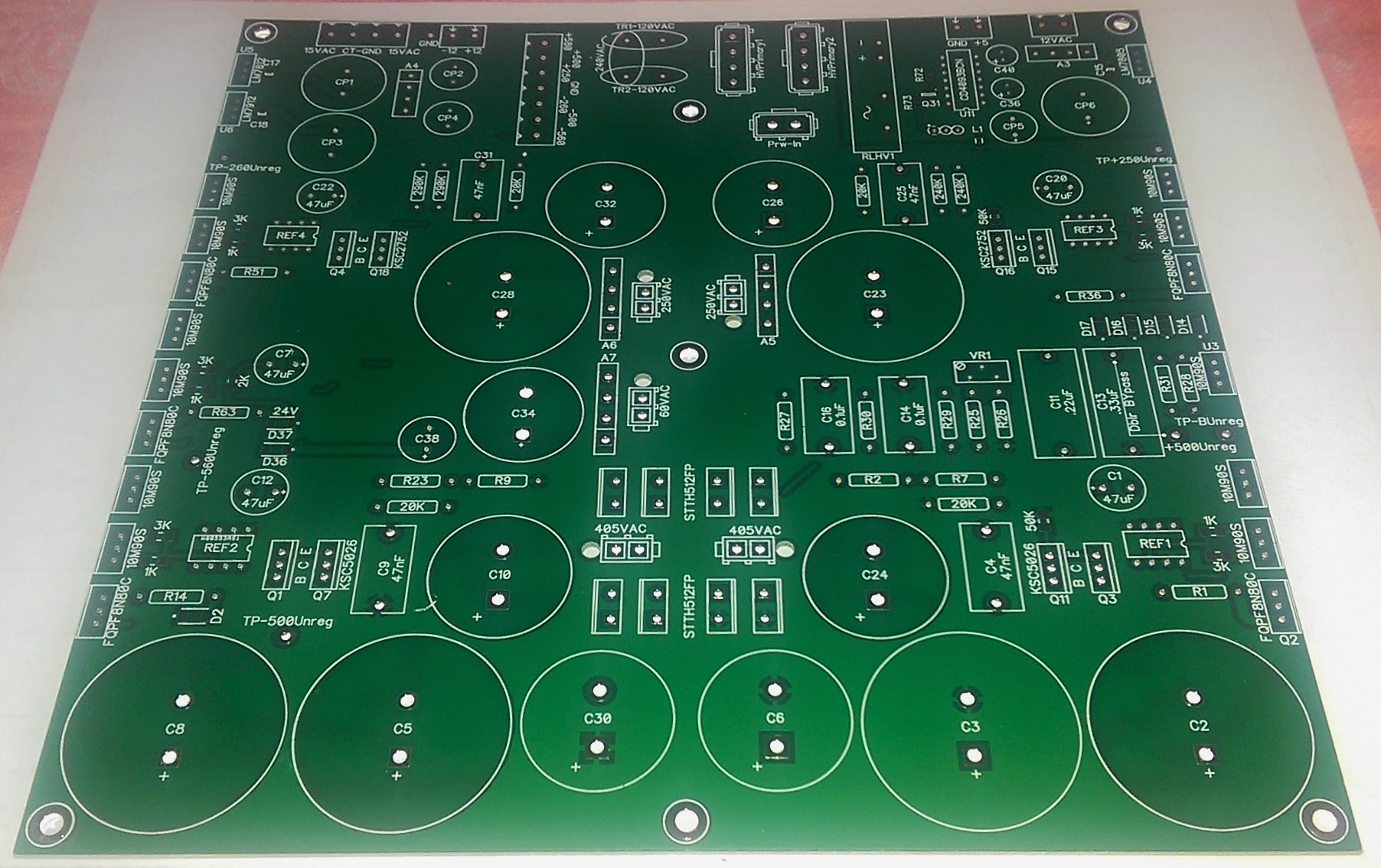
I do have a BOM for the original build. PM me and I can email it to you. In other news, I've been working on a shrunken version of the T2 inspired by Joamat. The bigger challenge was the PS which I've just gotten some boards back from manufacturing. Lot's of SMD parts especially on the bottom of the board. I've also included some 3D CAD drawings of what I think the chassis will look like. The PS board is 206mm (W) x 200mm (D). The chassis will be 12"(W) x 14.25" (D) x 3.33"(H). I'm using the new GR HV PS for all of the elements including the 60V supply. 12V supplies are still 7812/2912. I've also included a 5V supply since I wanted to use the new Digital attenuator. I should have parts next week and I'll show some more pics once I have the board built up. This is going to be fun
-
Spritzer stars in Innerfidelity Big Sound 2015 video - (but not in person!)
Kerry replied to complin's topic in Headphones
Good stuff. Nice to Spritzer's efforts being recognized outside of Head-Case -
Crafting Thread -- Ask Questions About Casework and Whatnot Here ...
Kerry replied to dsavitsk's topic in Do It Yourself
I've been able to get really great results on my drill press, but there are a couple of steps. I mark with a caliper, then using a sharp centering punch and a loop I make an indent. I then use a 1/8" center drill followed by a larger 1/4" center drill if needed. When I was building my mill there really wasn't much room for error and this seemed to work pretty well, though not perfectly. -
They look beautiful I am interested if you can hear or measure a difference based on the case size. I'm looking forward to building one. Looks like you have a Blue Hawaii in the works too. edit: Swipe type is awesome unless you don't proof read.
-
That is a nice looking case. Welcome to the world of DIY Stax amps. Enjoy.
-
1/2 watt is more than enough. Just make sure the voltage rating is at least 300v.
-
I like #4 for this board better, but either would work for me.
-
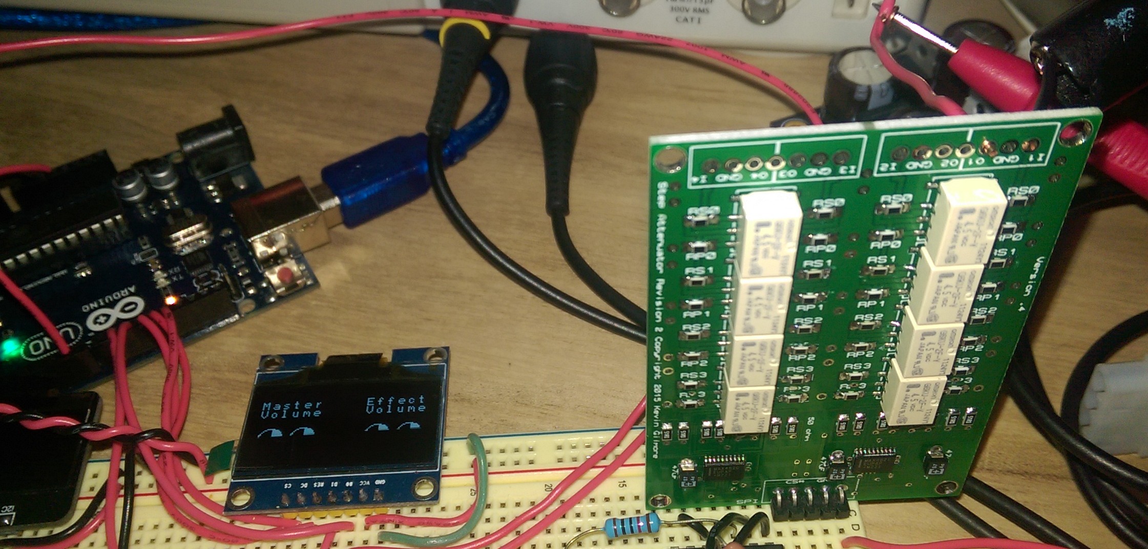
I tested the board out and it works perfectly I needed some time to figure out just how to program it, but I got it working now.
-
I've been using a hot air gun and solder paste. I'm really loving it.
-
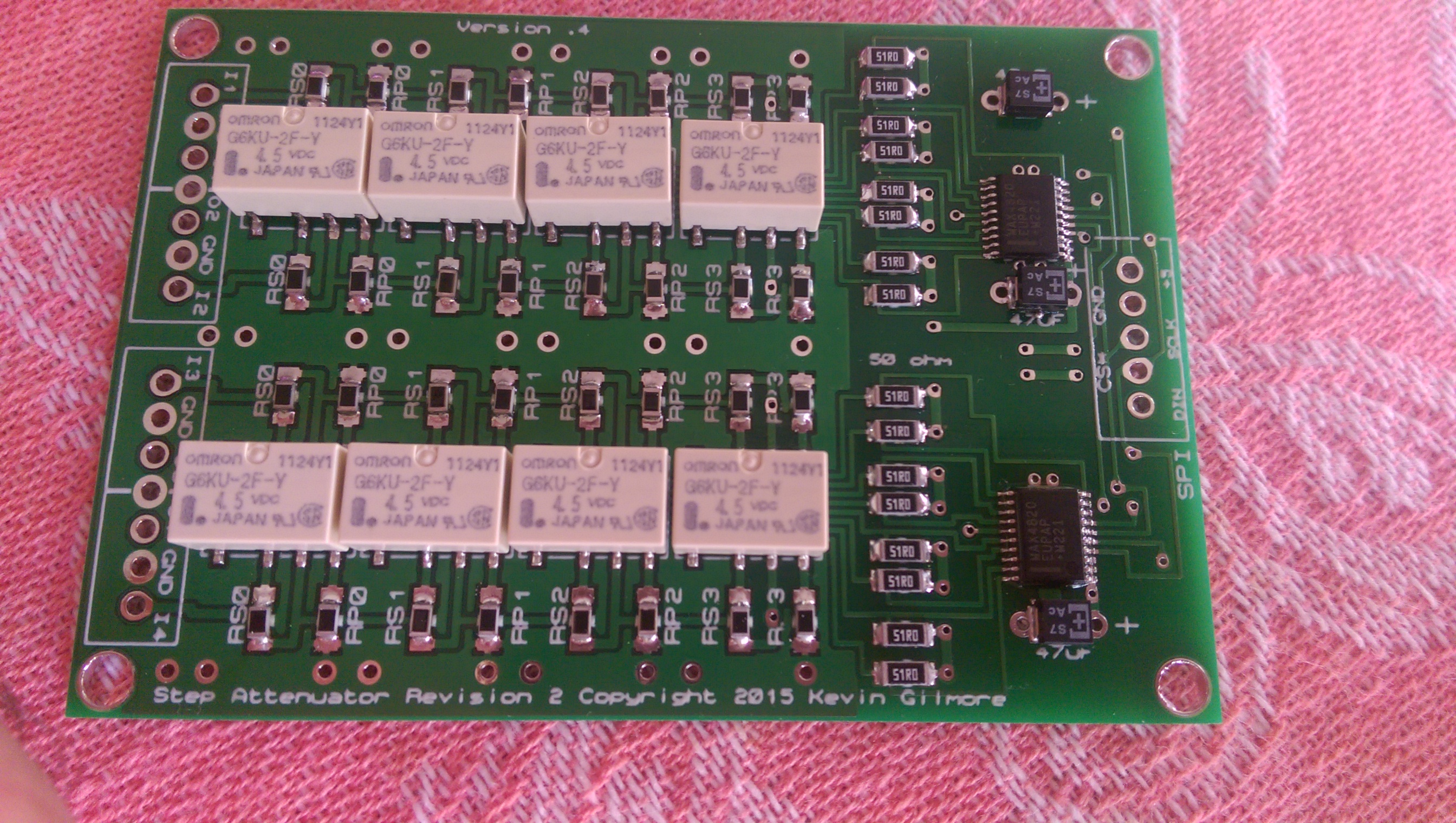
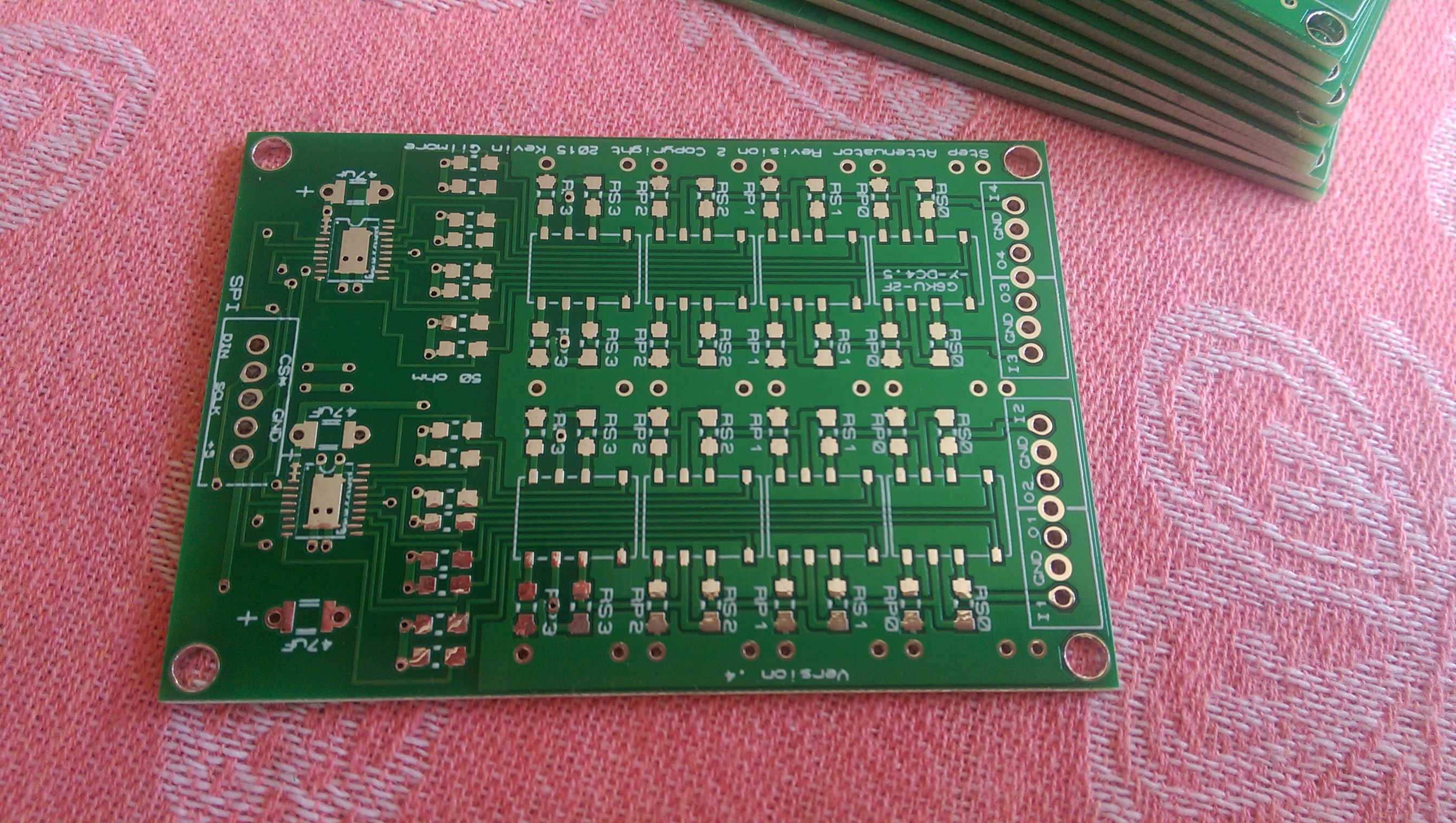
I just got these back and will try to build one this weekend

.png.4e8fb4e70793d4570d1c0440be01391a.png)
.png.54a0eaf2ff28058058d78d44524cfeb9.png)
.png.e9a3409f96a9d3235192864d17380a79.png)