-
Posts
2,292 -
Joined
-
Last visited
-
Days Won
12
Content Type
Profiles
Forums
Events
Everything posted by Kerry
-
Excellent! I'm curious if you were thinking of testing this same current source as a replacement for the battery (2mA to bias the CCS transistors) in the larger T2 as well. I'm curious how it compares to the batteries.
-
I like the idea of the solar cell. Very cool Here's what I was playing with for the LT1021... I got the idea from here... IXYS App Notes There are a couple of other interesting ideas in here as well.
-
I was wrong about not cascading the MOSFETs. It really did help. At this point, spice is showing me the same results as the battery. It would be nice if someone could check this to confirm. The models I'm using for the IXTP01N device seem to be optimistic. Note that J1 only helps if the top MOSFET performs worse. So, if the model is right, then you don't need J1 and we're right back to what Kevin was suggesting
-
I saw some noise issues in the Spice model for the regulator version as well. I could mostly control it, but not completely (especially once you go above 20KHz). Here's another idea I came up with (CSS #2 and #4). They will also support 1,000V. You could improve it slightly by adding a DN2540, but I'm not sure it's worth it. These other two models work almost as well as the battery at 10KHz and only a bit worse at 20KHz. The second (#2 below) is probably the best bang per parts. # 4 could be made to be a bit better, but I'm not sure it's worth it. The results are for the first three only (which includes the battery that Kevin came up with). R1 May not be necessary, but it felt good I want to experiment a bit more with it.
-
Yes, but the regulators perform much better in spice, especially at higher frequencies.
-
I've been playing with the current sources in spice. This one can cover 1000V and models really well. I'm not convinced the performance is not just LTSpice and the model I found for the IXTP01N100D. The LT1117 could be a LM317.
-
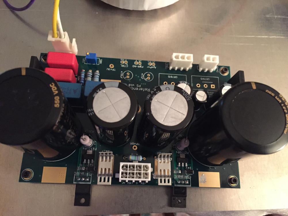
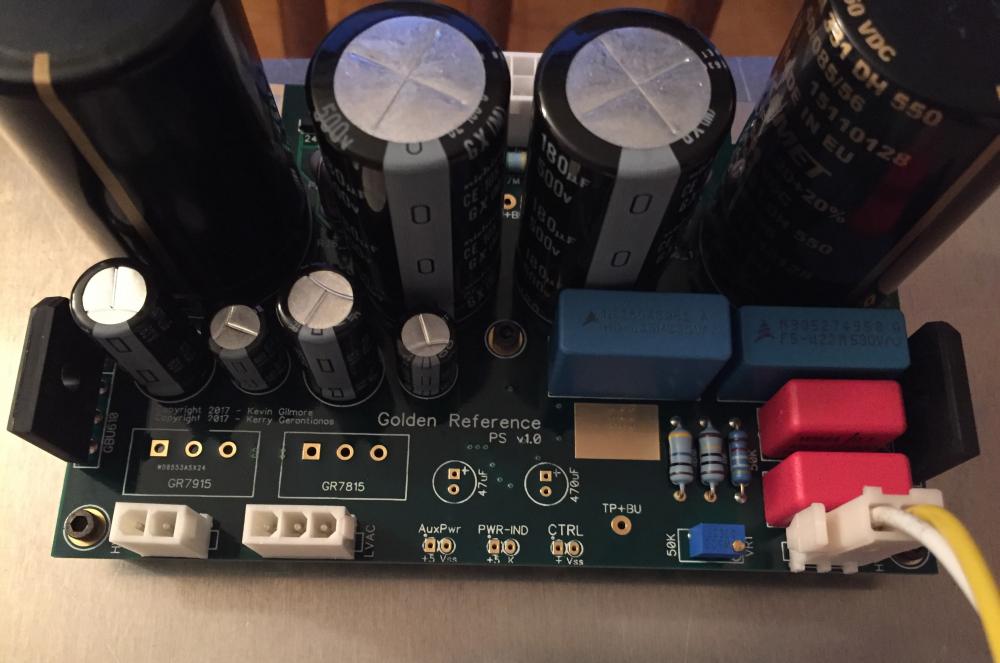
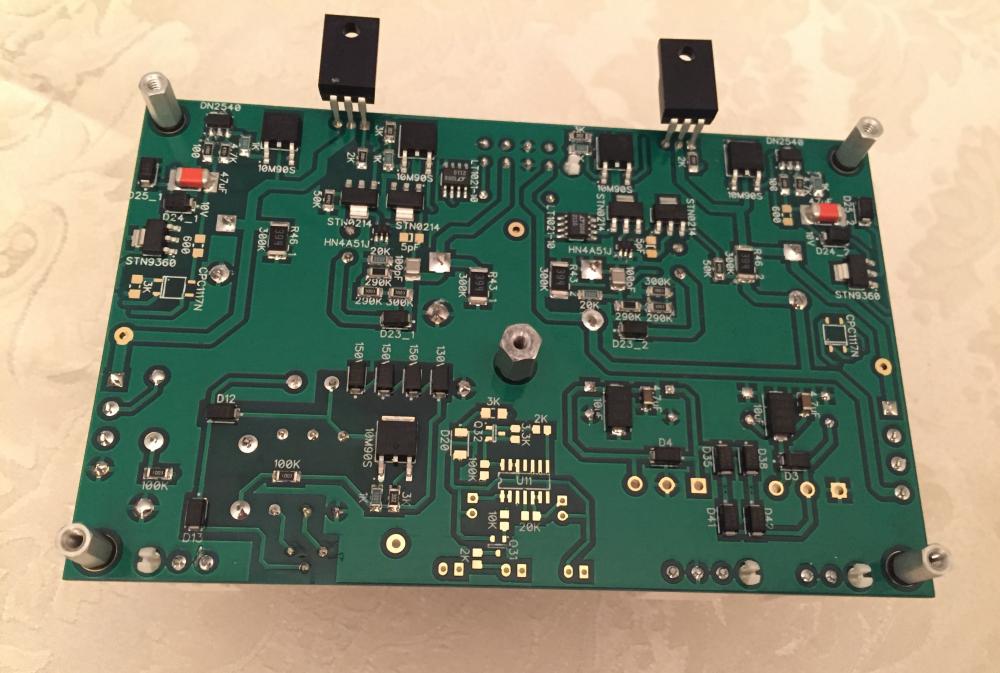
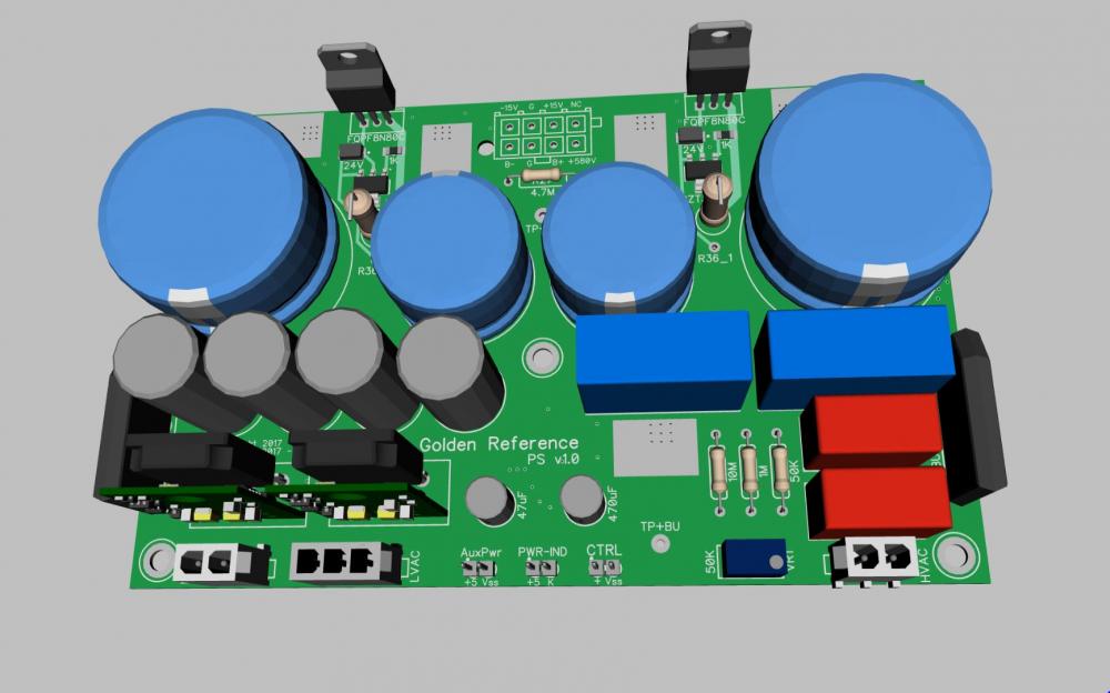
I got the HV sections and bias up and they work perfectly Here's the board... I've already tested the GRLV boards and they work. I just have to build another set for this supply. The thermals above the IXCY10M90S regulators don't go above 99 deg. F. Very happy with the board so far.
- 813 replies
-
- 16
-

-
Yeah, wish I had a big stock of a1968's. It's not so surprising the the grhv looks similar The two pnp transistors along with the current mirror below form a very simple opamp of sorts.
-
That works, but I don't think that is the source of that noise (I can't say this for sure). When I was working on Al's way back when, the solve for me was to replace all the resistors in the batteries with Xicons. I tried all of the other recommendations at the time with no success. I still don't have a great explanation of why this solved the issue. My new version of this amp uses the leds, fet and resistor to create the set voltage, same as the original, and does not have any issues.
-
Happy Birthday Brent!
-
Focus on the feedback bypass cap. I bet you can get rid of it there. I played with adding caps to a bunch of places (can't remember them all) and this was the solution for me. Do you have it on your smaller build, bigger build or both?
-
It only sees a few volts, but for safety sake you might try a higher value that could cover the voltage from ground to the negative rail. Can't wait to see how this performs EDIT: I'm noticing that the gaps between the ground plane and traces are very narrow (not sure if I'm seeing this right). If so, I'd recommend about .035".
-
On my build, which is much smaller, I did need to adjust the 5pF bypass caps. I was also seeing an oscillation which caused a similar voltage drop. I move them up to 15pF and everything is great. I agree with Craig, you can try lower values as well as higher, but keep checking to see if it's getting better or worse. It's still good news that you've gotten it closer.
-
Excellent! I think the right part number for Q16, Q18 is PBHV2160Z. That's what I'm seeing on the board as well. Q9 and Q10 should be the higher voltage version. Everything else you've mentioned should be good
-
Looking good @JoaMat Here's the new schematic with the updated servo. It would be very much appreciated if some folks could check Kevin's boards against this schematic. Thanks EDIT: Updated schematic to match transistor values.
-
Congrats! Sometimes taking the bulldozer approach by change extra parts is the easiest path I've done this when I've been stumped as well. Really glad you've got everything sorted out.
-
I've been playing a bit with the design. Trying to keep it to only +/-450V rails + filaments. I also wanted to see if I could keep the servo. Here's what I came up with. The 6DJ8's anodes are sitting at about 67V. I think this works well, but could easily shift the operating point for these. Q9 & 10 are dissipating about .46W, but we could do a thermal pad on the top of the board and should be good There's still some tweaking on some of the parts. Also, thought to do the 47 ohm hum bucker resistors to ground on the filaments. I've gotten the 200V supply down to about 5mA so not to bad on the pass fet (1.25W). I would embed this with each channel and mount to the heat sink. Could probably use FQPF8N80C here instead. The servo uses the HV opamp we use in the PS, etc. I'm running about 1mA though it. Models well, but need to test this. I've also brought the bottom up with the 400K resistor so we could use lower voltage transistors in it. Right now is sits at about 40V between R34 and R9. The output is sitting around -4V. I'll need to play with this a bit more, though this isn't a real issue. Definitely worth a build. Thanks Kevin EDIT: @JoaMat Have you finished building this yet EDIT 2: I'd love to experiment with the CCS with batteries as well.
-
Happy Birthday Justin! Enjoy the day
-
Yes. That will work.
-
-
I do use the cpc1117n relay to control the hv delay, but I've used my own layouts. The circuit is identical so it should work.
-
Happy Birthday Ari! Hope your doing well


