iemphile
-
Posts
6 -
Joined
-
Last visited
Content Type
Profiles
Forums
Events
Everything posted by iemphile
-
The Cree's I ordered from digikey in January arrived a few weeks ago, site still shows 0 in stock though. Maybe people preordered the entire batch?
-
I used a KBP210G successfully for a different amp.
-
I ordered some C2M1000170D from Digikey in January, estimated ship date was 3/19/2021.
-
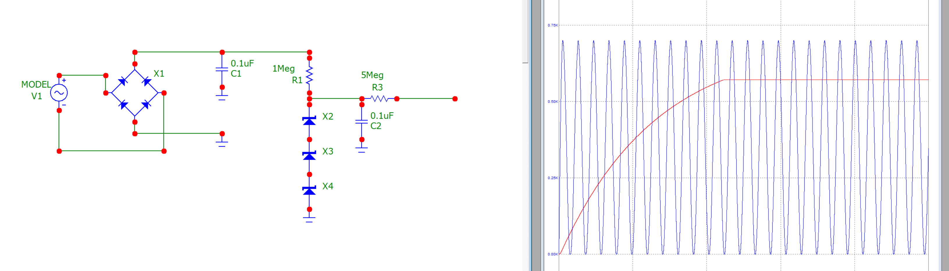
Hello all, I'm planning on building a transformer box, so I came up with this bias circuit. I'm a complete novice at circuit design but I would be grateful if anyone could critique it or rip it to shreds. V1 is supposed to be the 60hz output of a power transformer (I arbitrarily chose 700Vpp, but I tried it with 940Vpp and it seems to work too), and the zener string is 2x 200V and 1x 180V. Blue line is the sine source, red line the node right before the ballast resistor. The runtime of the simulation is 0.4 seconds. I know it's probably a waste of money to use a power transformer for a bias supply, but are there any issues with the idea other than cost?

-
I'm looking for books to read to better understand amplifier design. I'm mostly interested in solid state dynamic and electrostatic headphone amplifiers. I have taken some EE courses in college, but those were mostly theoretical or focused around digital devices and had little actual analog circuit design.
-
Listening to this excellent synthwave album at the moment. Perturbator - New Model