jamesmking
-
Posts
421 -
Joined
-
Last visited
-
Days Won
1
Content Type
Profiles
Forums
Events
Everything posted by jamesmking
-
goldenreference low voltage power supply
jamesmking replied to kevin gilmore's topic in Do It Yourself
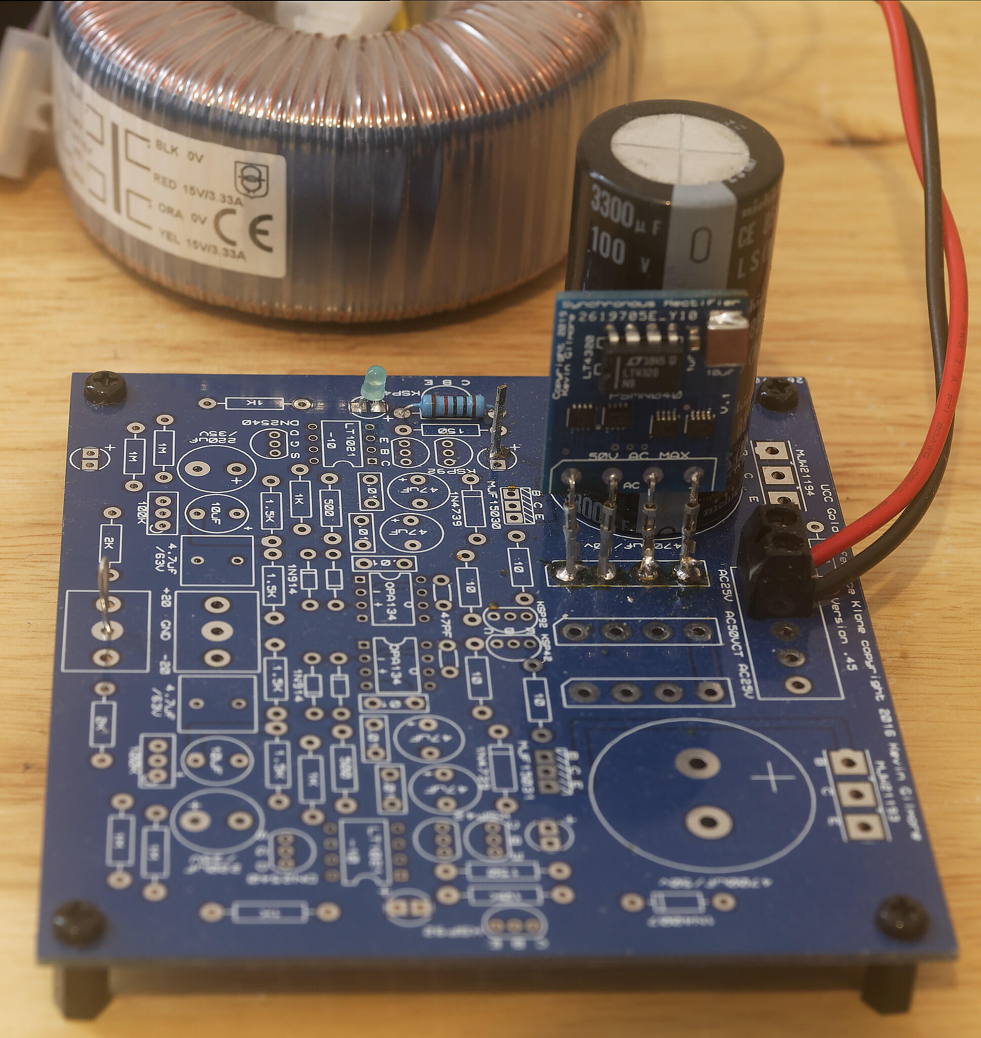
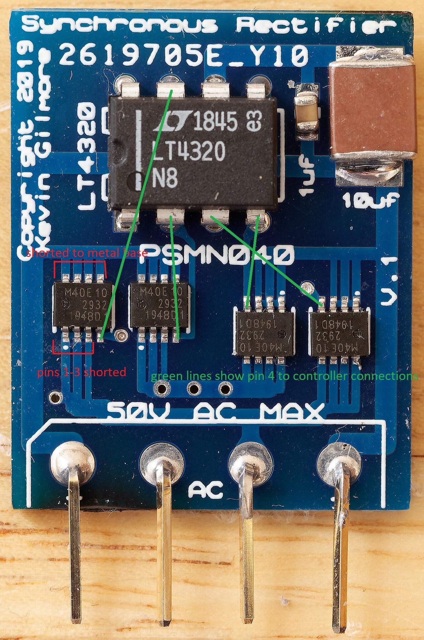
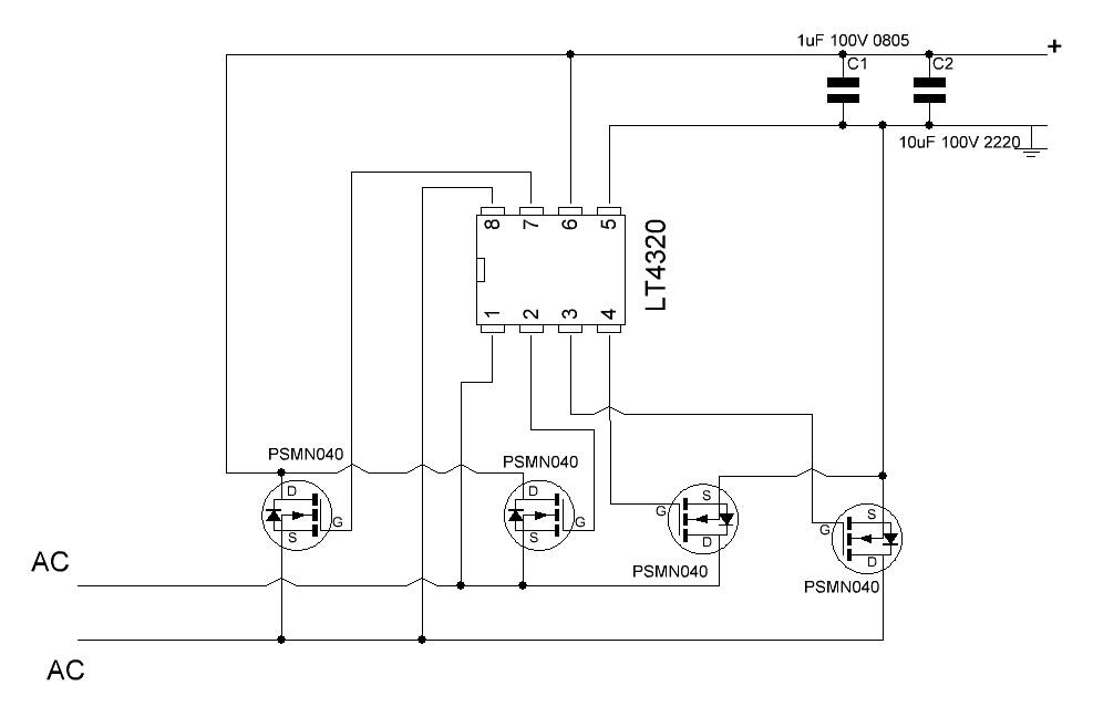
I have had no trouble using the zip with jlcpcb in china, I have sync rectifiers in my grlv in my blue hawaiis, mini t2s, psus I made for my dacs and a preamp I made,. Please be aware the sync rectifier will not work with centre tapped windings . so if you are making a grLV you need two independent windings and two sync rectifiers,. you cant use the GRLV option for centre tap and one rectifier I have tested it myself the sync rect does not work in this configuration but a normal diode rectifier does. The pin pitch is rather small and you need to check very carefully for shorts between pins 3 and 4, (pins 1-3 are internally connected together) and between the metal base and pins 1-4. I created a small test rig for the sync rect, I used a spare grlv board, put a female header where the rectifier solders in, added a largish value smoothing cap and bring the sync rectifier under test up slowly using a current limited dc supply and when I believe its ok, I swap the polarity of the dc supply and repeat so all 4 psmn040 are tested. I then use a 15v transformer and bring the sync rectifier up slowly on a variac. So far I have had one psmn040 smoke, I think I had a soldering short between the metal base and pins 1 or 2 or 3 or 4. Fortunately the expensive lt4320 survived without issue and I was able to reuse it. the test rig also includes wire loops for attaching a multi meter, scope and electronic dc load. I populated the diode next to the cap and one led partly to help drain the cap and to give a visual indication the board is live. Once the board has passed variac tests, I test switch on with no variac so the cap will cause a reasonable inrush, then I test with an electronic DC load up to 2A. .
-
goldenreference low voltage power supply
jamesmking replied to kevin gilmore's topic in Do It Yourself
joke { 5 digits is too low accuracy, you need at least a 8.5 digit multimeter calibrated monthly in a sealed controlled environment and Faraday cage. The resistors should all be 0.01% 5ppm or better and the leds need to be curve traced from 0V to 5V and matched within 0.01% on current. This should make the LV psu board more expensive and time consuming than the rest of the amp. 🙂 } /joke I don't know if the cfa has any special requirements but for both my blue hawaii and mini t2 builds I went for 1% 50ppm resistors, - koa brand. I did not match the leds other than they where all from the same reel and so had the same nominal specs. I aim for voltages within 1% of the target given I use 1% resistors. The ppm of the resistors will effect voltage drift with temperature, if you want good accuracy and stable voltages build the board with low ppm 1% resistors, measure the voltages, calculate the error and replace just the resistors that set the output voltage. I don't see any point in spending lots of money on better resistors everywhere when I can spend the money I save on music or other vices 😉 ... -
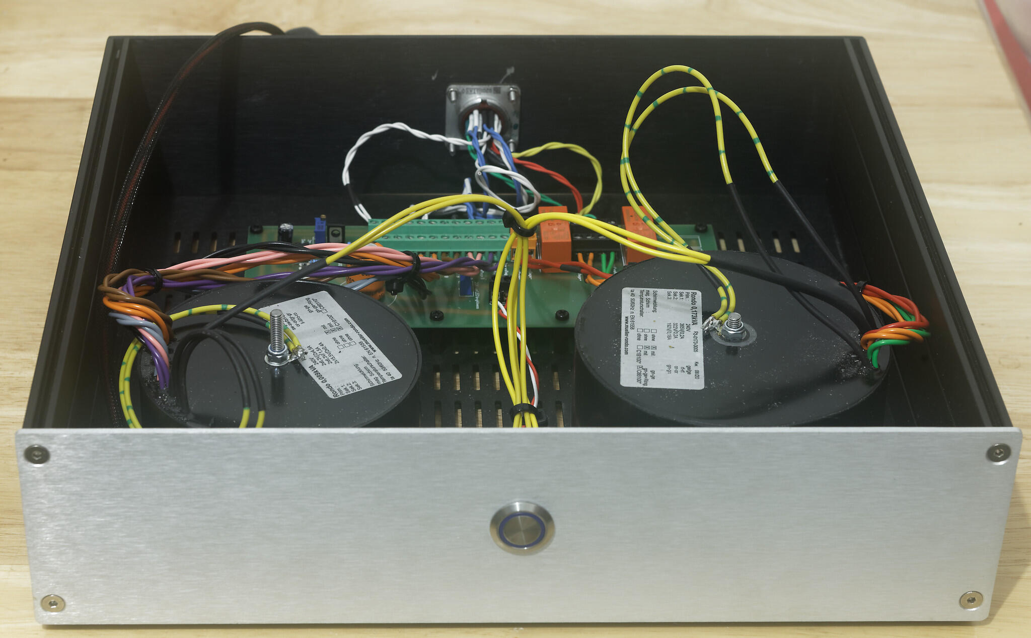
I used two transformers. both with electromagnetic shields, static shields and potted from http://www.mueller-rondo.com/kontakt.htm . (The low voltage transformer can be used for the blue hawaii - the 6922 windings are just not used the other voltages and currents are fine.) low voltage: transformer two windings 6.3V 4.5A for EL34 heaters one winding for each channel NOTE these windings are -400VDC to ground two windings 6.3V 1.5A for 6992 heaters one for each channel and my HT delay board two windings 15.5V 0.4A for golden reference LV board + and - 15VDC high voltage transformer one winding 365V 0.2A for dual golden reference HV board -460VDC. NOTE 365VAC gives 516VDC which gives less than 10% margin before reaching the 550V limit of most high voltage 550V 470uF input caps on the golden reference HV... so be careful if your household mains voltages are usually higher than spec. one winding 322V 0.2A for dual golden reference HV board +400VDC and +580V stax bias one winding 192V 0.18A for golden reference HV board +220VDC The blue hawaii just fits in a single 2u case 400mm deep, using 1 transformer with less windings - one less high voltage and two less 6.3V, golden reference LV board and golden reference HV board. The mini T2 has two transformers AND an extra HV board so the issue is not height but depth, to give you a size idea the transformers are Low voltage diameter 105mm height 55mm High voltage diameter 115mm height 65mm not having shields in the transformers will result in some hum and electrical interference if you turn the volume all the way up if you go single case. Not potting the transformers might make them a little smaller. putting the transformers into a separate case makes both the blue hawaii and mini t2 absolutely silent. you cant easily use the space bellow the mini t2 amp boards because they have 4 pillars which screw into the bottom of the case so you don't bend the amp boards when inserting or removing the valves. Neither the golden reference LV or HV boards will fit bellow the am boards because of this. for both my blue hawaii and mini t2 builds I went with the following case https://modushop.biz/site/index.php?route=product/product&path=102&product_id=195 its 2u, 400mm deep and has large heat sinking and is fully aluminium so fairly easy to drill. The heat sinking is overkill for the mini t2 - which runs quite cool, but the blue hawaii needs those large heat sinks, For the umbilical chord I used 1KV silicon rubber multi-strand copper hookup wires (https://www.mouser.co.uk/Search/Refine?Keyword=CT2956) for good flexibility and Russian 19 pin military connectors (https://www.ebay.co.uk/itm/19-pin-Soviet-Military-connector-Female-Male-Set-Oty-1/254196620095?ssPageName=STRK%3AMEBIDX%3AIT&_trksid=p2057872.m2749.l2649). I then covered the bundle with expandable nylon braid and tested the leads with an insulation tester and they passed 5 minutes at 2500V with 20+Gohm resistance. They failed insulation at 5KV. P.S. if you build golden reference HV boards kemet do 550V 470uF caps which are 65mm high and will fit in a 2u case https://www.mouser.co.uk/Passive-Components/_/N-5g73Z1yzvvqx?Keyword=kemet+550V+470uF&FS=True. Be careful Kemet also sell 680uF 550V caps that are 80mm high and will need a 3u case to fit . (https://www.mouser.co.uk/ProductDetail/KEMET/ALC10A681EL550?qs=%2Fha2pyFadug678O2NPlQ%2F8WMW0dBZWV2y30oREQu6XgezeenvV90cA%3D%3D). for the +220VDC golden ref board you can save some money and go kemet 470uf 450V or even 400V. I didnt simply because I might re-purpose the 220V board to a higher voltage sometime.But the 550v 470uF kemet caps are not cheap. P.S. the golden reference LV board is not necessary, only the servos are run from the + and - 15V lines so you could just populate the low voltage section of the GRHV board. However, if you don't want thumps on switch-off the + and -12V lines require large capacitors so the servos stay powered while the HV lines fade. I found ~15000uF to 22000uF is required but these caps are physically too large to fit in the simple LV section of the GRHV board. They fit fine in the GRLV board, but a full GRLV board is extra expense just to avoid switch off thump. I use GRLV boards in lots of projects so again they can be repurposed...
- 336 replies
-
- 10
-

-

-
Kerry Design mini GRHV\GRLV and JoaMat mini T2 Group Buy
jamesmking replied to mwl168's topic in Do It Yourself
Thank you. Paid -
OneGuy: "both hands free"?.... you also only have two hands? but can the reflow oven do double sided?
-
joamat: on the quick air flow 5 out of 120 !!! even then you can orbit small diodes if you release the tweezers before the solder has melted the quick is powerful, 120 will almost remove through hole comonents and your third arm.... maybe thats why mwl168 only has 2 hands.... temperature 330C to 360C depending upon ground plane, size of component. solder paste nothing special off ebay its MECHANIC XG-Z40 Liquid Solder Soldering Paste 10cc has a good amount of flux in it seems to work quite well for my soldering technique but then I have not tried any other paste.... mwl168: you DON'T have 3 hands?😕 My smd soldering method requires 2, left hand holding the twessers, right hand holding the hot air nozzle....
-
mini t2 is not alot more than a bh, a few extra transformer windings - it needs seperate windings for the 6922s and el34s, an extra 220V supply or dropper resistor, extra valve sockets and 4 6922 valves against that smd parts are generally cheaper than the through hole and I found that in many cases - especially the resistors buying 10 of a value in smd was cheaper than buying 6 - the bulk discounts scale much better than through hole. It is true that its possible to build a blue hawaii in a single case and still fit in golden reference LV and HV boards, its not realy possible to do this with the mini t2 so you need a second case and wiring between the cases. However, it is possible to fit all the pcbs in a case the same size as the blue hawaii and just have the transformers in a small cheap second case.... - which is what I have done.
-
tomislavkufrin There is the mini t2, if you dont mind surface mount for the amp boards, you can use exactly the same golden reference lv supply as the blue hawaii - zero changes, the same golden reference hv supply with two resistors changed to go from -400V to the mini t2 -460V, add another golden ref power supply for the +220V or a dropped resistor from the +400V to save an extra power supply board and transformer winding.. if you use two transformers - one to supply the heaters and the plus and minius 15V DC - that transformer can also be used on the blue hawaii the second transformer can supply the voltages for the 220V, -460V and +400V. I think the sound of the mini t2 is better than the blue hawaii (a big enough difference that my mini T2 is now my daily stax amp and the mini t2 runs cooler) and quite a lot of the mini t2 can be re purposed if you do decide to build a blue hawaii some time. The blue hawaii is also a nice amp if you dont want to do smd soldering. personally Im waiting for someone to design a reliable full diy t2 using modern components.... Kevin? JoaMat?
-
fuses degrade the sound 🙂
-
I got the quick based on a review my lewis rossmann on you tube who does apple mac repairs . I tend to be paranoid, so I assume solder paste will go under components and cause shorts... I plan to get some experience just dropping the components on the raw solder paste and applying heat, but I did not want to take the risk with the mini t2. My general philosophy is find something that works and then optimise it. there is one issue with my smd method... if you apply heat with the soldering iron for too long you burn off all the flux in the solder. So, a quick wipe with the iron is all that’s needed to get the solder to solidify on the pads. secondly any solder on the iron tip has no flux left so you should not apply the soldering iron to a pad that has no solder paste on it, otherwise the solder that will stick to the pad from the iron tip will have zero flux.
-
Kerry Design mini GRHV\GRLV and JoaMat mini T2 Group Buy
jamesmking replied to mwl168's topic in Do It Yourself
mwl168, I had a look at the bom for the gr78xx and tried to build a mouser project from it. However mouser says the kst42mtf is obsolete and out of stock. Also C3 C7 in the bom is the same as c1 and c2 but is on a seperate line... the gr79xx also uses the obsolete kst42mtf. the gr79xx also has two entries for the same cap, c1,c4 and the line c7. Ok looks like farnell still has some stock remaining.... -
Mini T2 Switch off thump. I have found that when switching off the mini t2 (golden reference LV and HV supplies) I get a thump on both channels around 3 to 4 seconds after pressing the off switch. I get no thump on switch on using a 45 second delayed HV so I guessed the LV was dropping faster than the HV at switch off. This was confirmed with a multimeter. Compared to the blue hawaii, the mini t2 drains the HV caps at a slower rate but drains the LV caps faster. I solved the switch off thump by replacing the standard 4700uF caps in the Lv supply with 22000uF. This provides significantly longer LV voltage on switch off and stops the thump. I used 30mm diameter Nichicon 22000uF 35V caps which just fit in place of the 50V 4700uF caps. I suspect 15000uF would probably work to. regards and happy mini t2ing
-
but I know the labels are now wrong, the incorrect labels may confuse the electrons and effect the sound. Before the mini T2 I had almost zero smd experience, I built some of Kevins synchronous rectifiers and built two dummy dc loads from a design on you tube which had some smd op amps and thats it. The first mini t2 pcb took 2 days with lots of breaks and lots of losing components, I went very slowly and checked every joint with a multi meter. the second channel took half a day. I used a quick 861DW hot air station and that helped, it has very good control over the airflow and temperature so I could experiment and get repeatable results. I still managed to send the odd diode into low earth orbit even with the airflow set to 5 out of 120! I found that having a led table lamp on my left, a fume extractor on my right, tweezers holding the component in my left hand and the quick hot air nozzle in my right hand worked for me well. Im right handed but I managed to control the component with tweezers in my left hand ok after a little practice. I purchased from ebay a head mounted visor magnifier https://www.ebay.co.uk/itm/Toolzone-Head-Mounted-Magnifier-2-Leds-Magnifying-Glasses-Repairs-Jewellery/133310425999?hash=item1f09ebab8f:g:NtgAAOSwp2deJYjP The magnifier works and you get the choice of different magnification lenses, the headband is horrible - just plastic with no elastic to help tension.... so you either have it too loose or head crushingly tight. the light is crap and the handband uncomfortable, but it was cheap and made the HN4A51 soldering and board inspection a lot easier. Good luck with your build. Fingers crossed it goes as well for you s it did for me.
-
I did the flip 🙂 the small signal tubes are at the front but the labels on the pcbs for left and right and now wrong 🙃 I have the input wires going straight from the back to the tkd pot in the middle of the front panel and then nice short wires from the tkd to the boards inputs... heater wires route around the edge of the pcb close to the heatsinks. So far with the volume all the way up zero listenable hum.
-
Some small changes I personally would like to see to the mini T2, based on my build style. 1. space for screw terminals for the transformer to el34 heater wires - I like to be able to remove boards easily for testing/inpsection etc without having to desolder anything. 2. more space between the 6922 heater screw terminal and the valve sockets. - its a bit tight. 3. the ground plane not connected to the screw holes for the heatsink L bracket. I like to mains earth my casework and leave the amp ground foating. 4. the screw terminal holes grouped like the blue hawaii, so I can use terminal blocks without having to cut a 2 way into a 1 way.. plus the one way can twist easily if you dont hold it when you tighten the screw. 5. a second ground screw terminal, - so I can have one connect to the psu pcbs and the other connect to the input signal ground. 6. have the 6922s at the front... more valves visible more orange glow 🙂
-
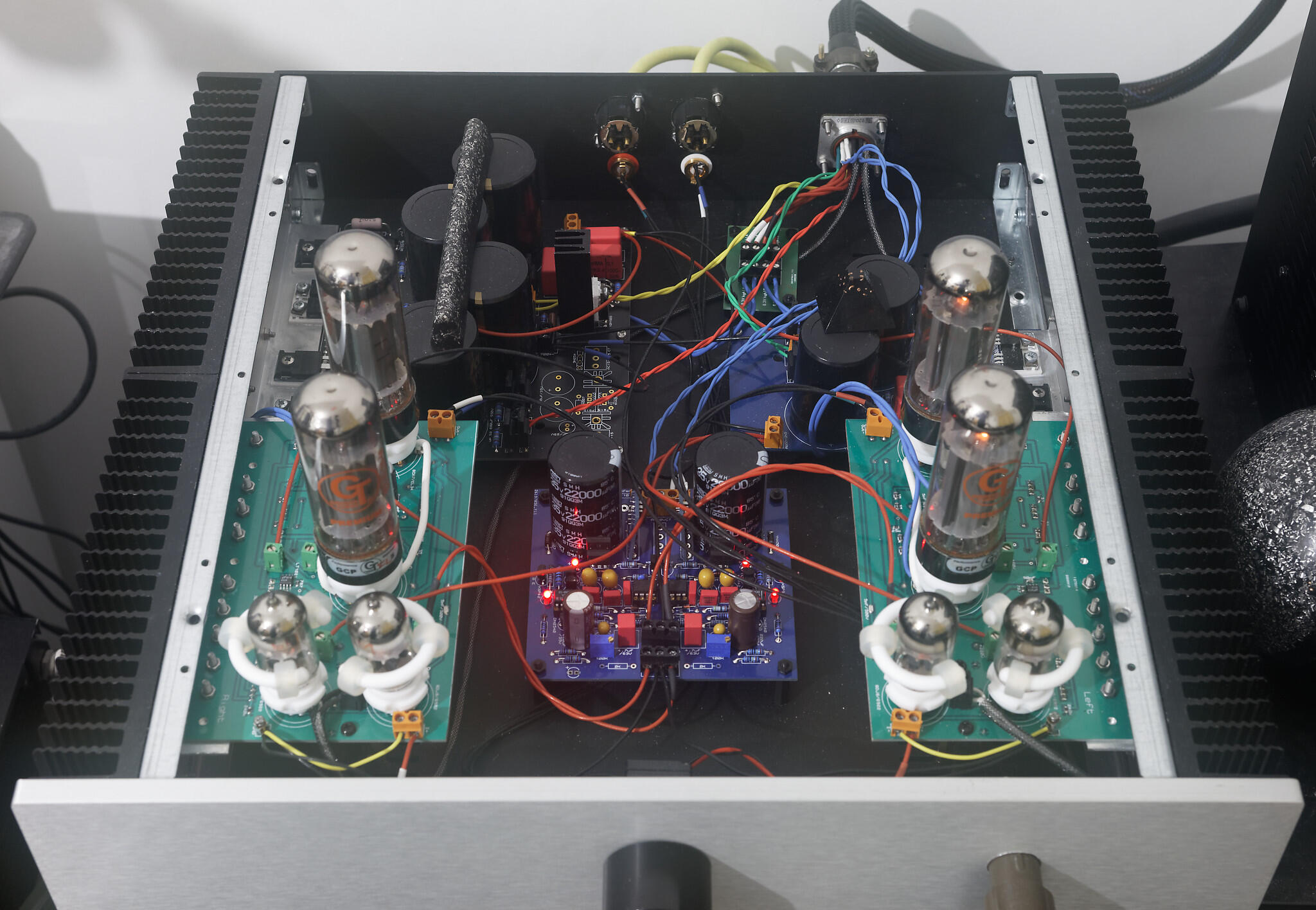
My Initial impressions of the mini T2. Listening on my stax 007a mk2, normal caveats apply. There is no point comparing it to the Stax srm007 its like comparing a Bentley to a slug. Compared to my hi-amp alpha centauri there is also no competition. The mini T2 out does it in every department as does my Blue Hawaii. I will compare the mini T2 to the Blue Hawaii (mini t2 (golden ref HV and LV, kevin gilmore synchronous rectifiers in the LV tkd volume, cardas hookup wire, groove tubes el34s, electro harmonix gold pin 6922s, simulated single box - transformers piled on top of each other 😞) (blue hawaii, (golden ref HV and LV, kevin gilmore synchronous rectifiers in the LV tkd volume, cardas hookup wire, groove tubes el34s single box) The t2 has more smoothness, and yet more detailed and faster treble with a little more sparkle than the BH. The treble speed is not done via a bright hardness but rather its just fast and articulate and is very musical and "valve like". Mid range is equally strong with more smoothness and more detail than the hawaii. Bass is good, not necessarily much better than the blue hawaii, perhaps the BH goes deeper but the mini T2 is again more rounded and smooth. I think the upper bass is better on the mini t2 which partly makes up for the slight lack of depth. The mini T2 does not shout or dazzle, its just fast and natural. It makes you want to turn the volume up, not because its missing something but because it sounds like its not straining and just wants to sing. Micro dynamics are much better than my BH, Macro dynamics are perhaps a bit more restrained than the BH but the compromise works for me because the micro is so much better then the BH. The mini T2 loves strings and acoustic music. I can’t comment much beyond this since I only listen to Jazz and classical. Image placement is like a blanket around the listener, the Mini has the ability to present the sound stage close to the listener when the recording is close. With the BH everything seems about the same distance regardless of the recording. When the recording has the sound stage further back the mini T2 presents a very wide, detailed soundstage but does not hyper focus on individual instruments, there is detail and yet the acoustic of the venue comes through. I feel the mini T 2is less analytical than the BH, interplay between instruments is better presented, its more musical and makes you want to play at whatever volume you want. there is much less of a volume sweet spot than the BH. Some suggested listening for what this amp can do Rodrigo guitar concertos academy of st martin in the fields philips - beautiful guitar sounds with detail and fantastic plucked strings. Hank Thompson live at the golden nugget. - the mini t2 pulls off the orange blossom special without brightness and the level of detail shows you it’s a packed venue with gambling noises everywhere. j c Bach trio sonatas on chandos - mini t2 shows the mid range warmth that the blue hawaii missing, the recording is on original instruments and can sound a little thin... no so with the mini t2 paul desmond bossa antigua, tape hiss is separate from the instruments, centre drums are articulate, it’s a warm sound but not dull or muddy. The sound is beautiful there is detail but it’s not thrown at you. I am very glad I started this project - even though I had very little smd soldering experience. Everything worked first time no smoke no drama. Now all I need is some cnc machining for the case. the mini T2 consumes about 25W less than the BH and runs cooler too. Conclusion, both the BH and mini T2 are very very good. Building a blue hawaii is easier - there is almost no smd parts and will be cheaper: one less psu board, less transformer windings, less valves and can be built in one box. But the mini T2 is better sounding..... If you have the time, money, skill and equipment give the mini T2 some serious consideration. Now I have to build a full T2 with modern components.... and finally a very large thank you to JoaMat for providing me the mini t2 boards and for his help and support during this build. Best regards and happy building James
-
My transformers have arrived! and I have begun initial amp board testing. A few more mini T2 build notes/observations. Once the amp boards are completed using diode test on a multimeter across the leds will not make them light. The 2 red leds on the underside of the amp boards will not light if just heaters and + and -15V are applied... you need the high voltages too. The el34s heaters run at about -400V DC with respect to ground plane on the amp board, the 6922 heaters run just about 0V with respect to ground. The attachment holes in the pcb for the heatsink L bracket are plated and connected to the amp boards ground plane. So the L bracket, and therefore the heatsink and ultimately the entire case is connected to the pcb ground plane. I have decideed to turn the amp boards around so the 6922 are at the front... to me it looks more visually pleasing... 🙃
-
Well spotted Mirko, you are correct. I will update the schematic.
-
I added the red anode mark myself when I tested the leds with a multimeter.
-
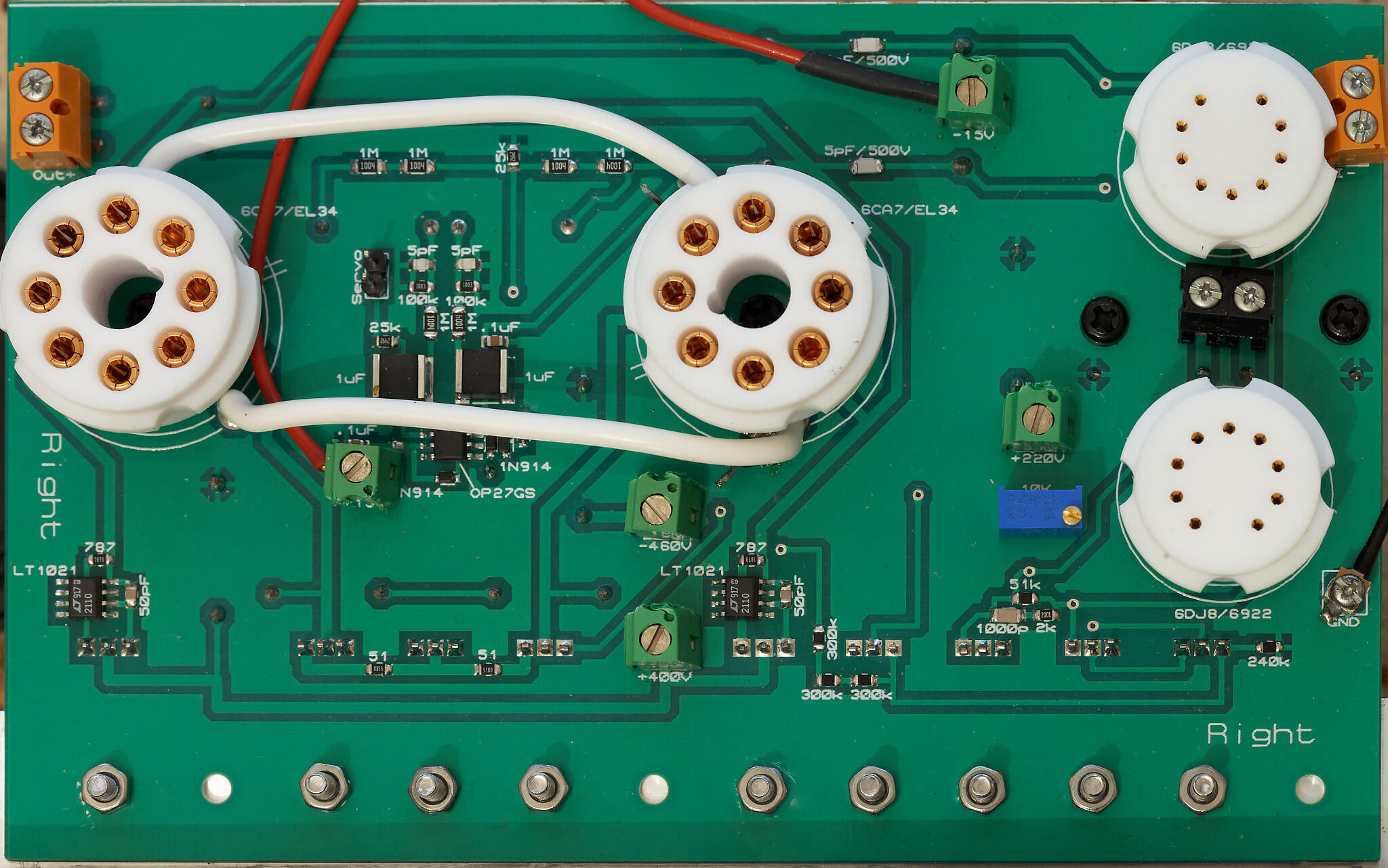
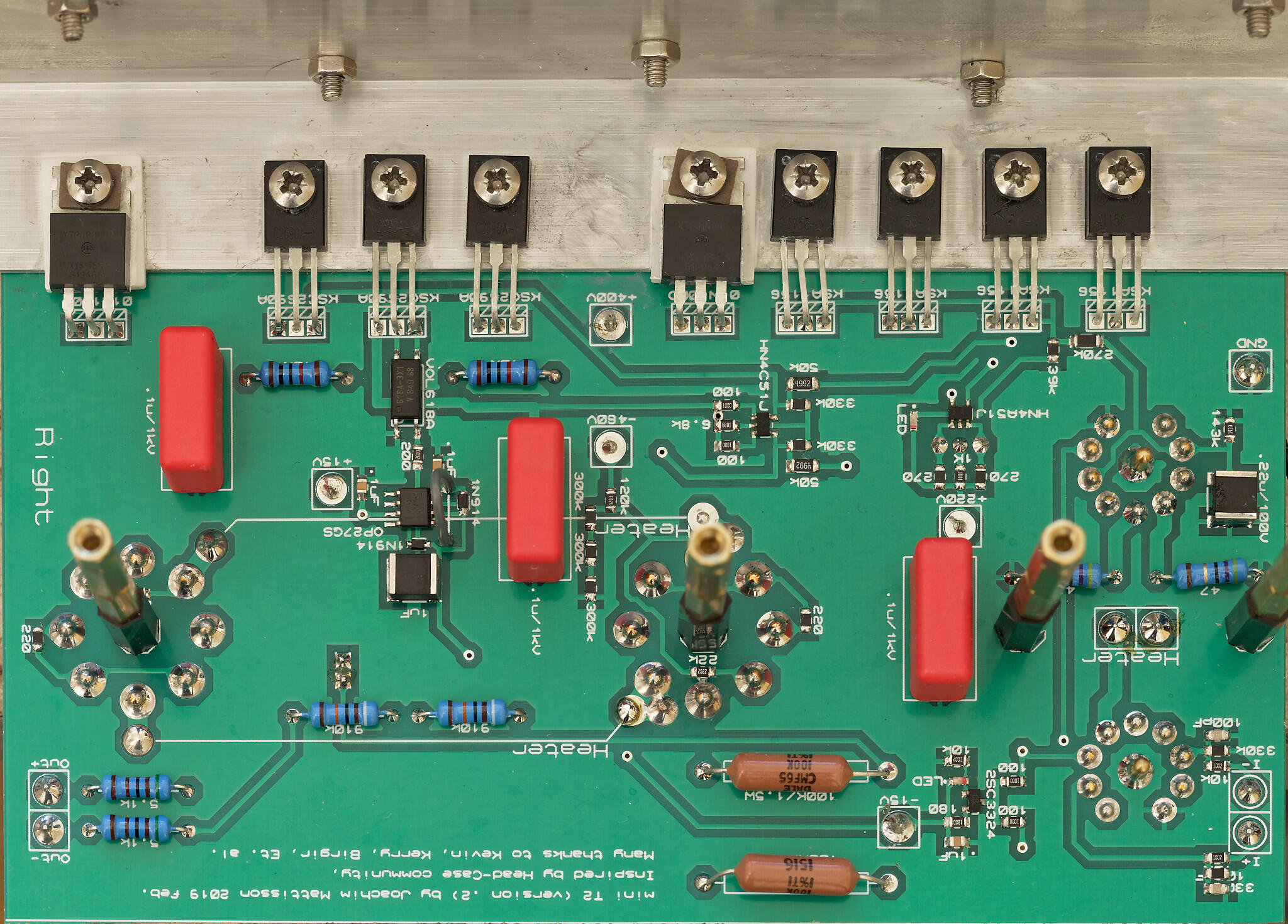
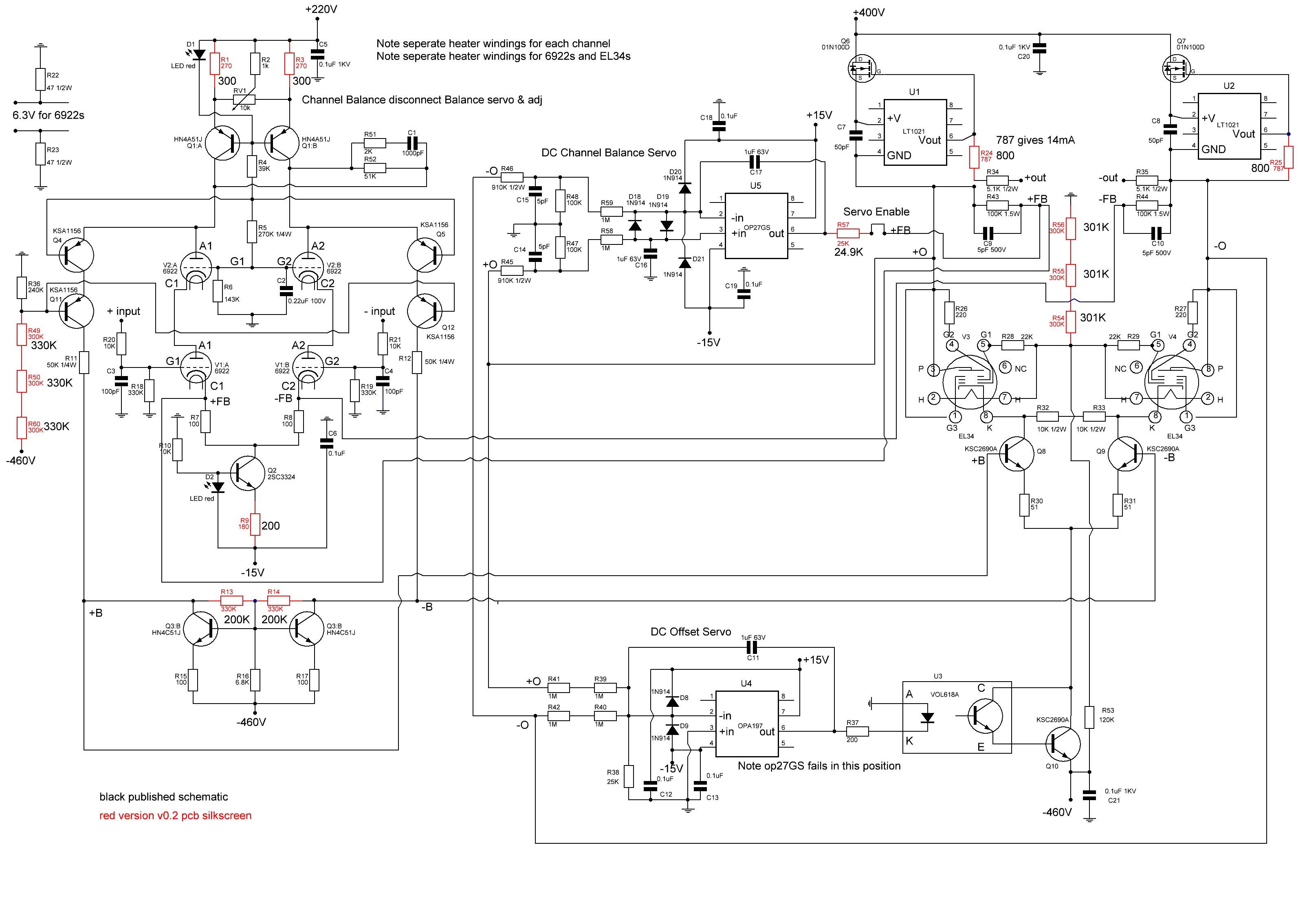
My mini T2 amp boards. Note the screw terminals on the top to make troubleshooting easier I know JoaMat does not believe in screw terminals but I do. 😉. If you are careful its even possible to orientate the terminals so the silkscreen voltage markings are still visible 🙂 . I take a 2 terminal and cut it in half and put the original smooth side parallel to the silkscreen markings. There is not space for screw terminals for the heaters of the el34s so I (possibly temporarily) have soldered in a header pin at 45 dgrees I have used nylon m3 standoffs for the first layer so that there is no chance of the standoff shorting against anything and brass standoffs for the remaining layers to get to the required height. SMD soldering was done in a three step process. 1 apply solder paste to the pads. 2. melt the solder using a hakko 888D station at 330 degree C using a fine tip until the paste has migrated to only be on the pads. 3 Hold the component with twisers onto the pads and with my other hand use a Quick 861DA hot air station using the smallest supplied nozzle with airflow setting all the way down to 5 (even then its possible to send one of the small diodes into orbit with that air flow)... to reflow the solder onto the component. the reason I soldered this way was, 1. I could collect any excess solder with the hakko, since I dont have an electronic solder paste dispenser... 😞 2. I could be reasonably certain there was no solder paste left under a component. I use the same method for soldering Kevins' synchronous rectifiers. this is the schematic of the v0.2 pcb with valves from the silkscreen. The red components have changed since the last published schematic.
-
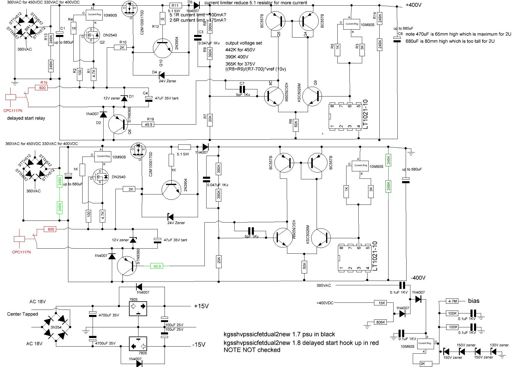
Pars, here is my reverse engineering of the kgsshvpssicfetdual2new I have added in red the extra parts for the delayed turn on but there are no pads present on the gerbers for them. As far as I can tell the dual hv boards stopped at version 1.7 just before the cpc117n was added. the individual "left" and ""right" boards went to version 1.8 - which included the cpc117n and the 600ohm resistor.
-
Pars for the golden ref HV on both my blue hawaii builds and my current mini T2 build I used the gerbers from the file kgsshvpssicfetdual2new This board does not have the cpc117n for the delayed start - but you can implement it via external relays. I made my own bom for it. Note you will need to change a couple of resistors if you dont want +-400V also if you are going golden reference dual LV you dont need the parts for the simple +-15V, the voltage regs, this are marked on the bom as for low voltage section. Hope this helps. On the silkscreen the caps are 0.047uF 1KV not 0.47uF, So you might be looking at a different board from the golden ref HV I used. Select Mouser No: 941-C2M1000170D Mfr. No: C2M1000170D Manufacturer: Cree, Inc. Desc.: MOSFET SIC MOSFET 1700V RDS ON 1 Ohm RoHS RoHS Compliant Availability 2 Dispatches Now £4.07 £8.14 Select Mouser No: 747-IXCP10M90S Mfr. No: IXCP10M90S Manufacturer: IXYS Desc.: Current & Power Monitors & Regulators 900V 1-100mA RoHS RoHS Compliant Availability 5 Dispatches Now £2.60 £13.00 Select Mouser No: 511-STN9360 Mfr. No: STN9360 Manufacturer: STMicroelectronics Desc.: Bipolar Transistors - BJT Hi Vltg fast-switch PNP pwr transistor RoHS RoHS Compliant Packaging Choice:Cut Tape Availability 2 Dispatches Now £0.697 £1.39 Select Mouser No: 512-2N3904TA Mfr. No: 2N3904TA Manufacturer: ON Semiconductor Desc.: Bipolar Transistors - BJT NPN Transistor General Purpose RoHS RoHS Compliant Availability 2 Dispatches Now £0.163 £0.33 Select Mouser No: 512-BC557BTA Mfr. No: BC557BTA Manufacturer: ON Semiconductor Desc.: Bipolar Transistors - BJT TO-92 PNP GP AMP RoHS RoHS Compliant - - Add new 4 Availability 4 Dispatches Now £0.178 £0.71 Select Mouser No: 512-KSC5026MOS Mfr. No: KSC5026MOS Manufacturer: ON Semiconductor Desc.: Bipolar Transistors - BJT NPN Si Transistor RoHS RoHS Compliant Availability 4 Dispatches Now £0.557 £2.23 Select Mouser No: 689-DN2540N5-G Mfr. No: DN2540N5-G Manufacturer: Microchip Desc.: MOSFET 400V 25Ohm RoHS RoHS Compliant Availability 2 Dispatches Now £1.01 £2.02 Select Mouser No: 584-LT1021DCN8-10PBF Mfr. No: LT1021DCN8-10#PBF Manufacturer: Analog Devices Inc. Desc.: Voltage References Prec 10V Ref 20ppm/-uC RoHS RoHS Compliant Availability 2 Dispatches Now £4.97 £9.94 Select Mouser No: 513-NJM7815FA Mfr. No: NJM7815FA Manufacturer: NJR Desc.: Linear Voltage Regulators 15V 1.5A 3 Terminal RoHS RoHS Compliant - - Add new for low voltage secti Availability 1 Dispatches Now £0.458 £0.46 Select Mouser No: 513-NJM7915FA Mfr. No: NJM7915FA Manufacturer: NJR Desc.: Linear Voltage Regulators -15V 1.5A 3 Terminal RoHS RoHS Compliant Lifecycle: End of Life: Scheduled for obsolescence and will be discontinued by the manufacturer. - - Add new for low voltage secti Availability 1 Dispatches Now £0.963 £0.96 Select Mouser No: 660-MF1/2CC1000F Mfr. No: MF1/2CC1000F Manufacturer: KOA Speer Desc.: Metal Film Resistors - Through Hole 100ohms 1% 50PPM RoHS RoHS Compliant Availability 2 Dispatches Now £0.147 £0.29 Select Mouser No: 660-MF1/2CC1001F Mfr. No: MF1/2CC1001F Manufacturer: KOA Speer Desc.: Metal Film Resistors - Through Hole 1K 1% 50PPM RoHS RoHS Compliant Availability 6 Dispatches Now £0.164 £0.98 Select Mouser No: 660-MF1/2CC1003F Mfr. No: MF1/2CC1003F Manufacturer: KOA Speer Desc.: Metal Film Resistors - Through Hole 100K 1% 50PPM RoHS RoHS Compliant - - Add new for headphones bias Availability 2 Dispatches Now £0.26 £0.52 Select Mouser No: 660-MF1/2CC1502F Mfr. No: MF1/2CC1502F Manufacturer: KOA Speer Desc.: Metal Film Resistors - Through Hole 15K 1% 50PPM RoHS RoHS Compliant - - Add new for headphones bias Availability 1 Dispatches Now £0.164 £0.16 Select Mouser No: 660-MF1/2CC2001F Mfr. No: MF1/2CC2001F Manufacturer: KOA Speer Desc.: Metal Film Resistors - Through Hole 2K 1% 50PPM RoHS RoHS Compliant Availability 2 Dispatches Now £0.147 £0.29 Select Mouser No: 660-MF1/2CC2002F Mfr. No: MF1/2CC2002F Manufacturer: KOA Speer Desc.: Metal Film Resistors - Through Hole 20Kohms 1% 50PPM RoHS RoHS Compliant Availability 2 Dispatches Now £0.164 £0.33 Select Mouser No: 71-RN60D-F-390K Mfr. No: RN60D3903FB14 Manufacturer: Vishay Desc.: Metal Film Resistors - Through Hole 1/4watt 390Kohms 1% 100ppm RoHS No Availability 0 Dispatches Now 4 Backordered £0.364 £1.46 Select Mouser No: 660-MF1/2CC2493F Mfr. No: MF1/2CC2493F Manufacturer: KOA Speer Desc.: Metal Film Resistors - Through Hole 249Kohms 1% 50PPM RoHS RoHS Compliant Availability 8 Dispatches Now £0.164 £1.31 Select Mouser No: 660-MF1/2CC4701F Mfr. No: MF1/2CC4701F Manufacturer: KOA Speer Desc.: Metal Film Resistors - Through Hole 4.7K 1% 50PPM RoHS RoHS Compliant Availability 2 Dispatches Now £0.164 £0.33 Select Mouser No: 660-MF1/2CC4992F Mfr. No: MF1/2CC4992F Manufacturer: KOA Speer Desc.: Metal Film Resistors - Through Hole 49.9Kohms 1% 50PPM RoHS RoHS Compliant Availability 2 Dispatches Now £0.164 £0.33 Select Mouser No: 660-MF1/2CC49R9F Mfr. No: MF1/2CC49R9F Manufacturer: KOA Speer Desc.: Metal Film Resistors - Through Hole 49.9ohms 1% 50PPM RoHS RoHS Compliant - - Add new 20 Availability 2 Dispatches Now £0.303 £0.61 Select Mouser No: 660-MOSX3CT521R5R1J Mfr. No: MOSX3CT521R5R1J Manufacturer: KOA Speer Desc.: Metal Oxide Resistors RSS3 5.1 5%TR RoHS RoHS Compliant - - Add new 2 Availability 3 Dispatches Now £0.181 £0.54 Select Mouser No: 660-MS1/2DCT52R3011 Mfr. No: MFS1/2DCT52R3011F Manufacturer: KOA Speer Desc.: Metal Film Resistors - Through Hole 1/2W3.01K ohm 1% RoHS RoHS Compliant - - Add new 1 for for headphones Availability 3 Dispatches Now £0.087 £0.26 Select Mouser No: 71-RN60D-F-806K Mfr. No: RN60D8063FB14 Manufacturer: Vishay Desc.: Metal Film Resistors - Through Hole 1/4watt 806Kohms 1% 100ppm RoHS No - - Add new for headphones bias Availability 1 Dispatches Now £0.201 £0.20 Select Mouser No: 594-VR37000004704FR5 Mfr. No: VR37000004704FR500 Manufacturer: Vishay Desc.: Metal Film Resistors - Through Hole 1/2watt 4.7Mohms 1% RoHS RoHS Compliant By Exemption - - Add new for headphones bias Availability 1 Dispatches Now £0.457 £0.46 Select Mouser No: 505-M100.047/1000/5 Mfr. No: MKP10-.047/1000/5 Manufacturer: WIMA Desc.: Film Capacitors 1000V .047uF 5% PCM15 RoHS RoHS Compliant - - Add new 2 Availability 2 Dispatches Now £0.64 £1.28 Select Mouser No: 505-MKS4.1/1000/10 Mfr. No: MKS4O131004J00KSSD Manufacturer: WIMA Desc.: Film Capacitors 1KV 0.1uF 10% PCM15 RoHS RoHS Compliant - - Add new for headphones bias Availability 4 Dispatches Now £0.718 £2.87 Select Mouser No: 581-TAP476K035CCS Mfr. No: TAP476K035CCS Manufacturer: AVX Desc.: Tantalum Capacitors - Solid Leaded 35V 47uF 10% ESR=800 mOhm RoHS RoHS Compliant Availability 2 Dispatches Now £3.77 £7.54 Select Mouser No: 75-561R10TCCV50 Mfr. No: 561R10TCCV50 Manufacturer: Vishay Desc.: Ceramic Disc Capacitors 1Kvolts 5pF 5% .25LS NPO RoHS RoHS Compliant By Exemption Availability 2 Dispatches Now £0.596 £1.19 Select Mouser No: 667-EEU-FR1E101 Mfr. No: EEU-FR1E101 Manufacturer: Panasonic Desc.: Aluminium Electrolytic Capacitors - Radial Leaded 25VDC 100uF 6.3x11.2mm LS2.5mm RoHS RoHS Compliant - - Add new for low voltage secti Availability 2 Dispatches Now £0.248 £0.50 Select Mouser No: 661-EKYB350E472ML40S Mfr. No: EKYB350ELL472ML40S Manufacturer: United Chemi-Con (UCC) Desc.: Aluminium Electrolytic Capacitors - Radial Leaded 35V 4700uF 20% Tol. RoHS RoHS Compliant - - Add new for low voltage secti 2 Availability 0 Dispatches Now 2 Backordered £2.05 £4.10 Select Mouser No: 80-ALC10A471EH550 Mfr. No: ALC10A471EH550 Manufacturer: KEMET Desc.: Aluminium Electrolytic Capacitors - Snap In 550V 470uF 20% 18k Hours RoHS RoHS Compliant Info: View Additional Product Info Availability 4 Dispatches Now £19.00 £76.00 Select Mouser No: 863-1N5927BRLG Mfr. No: 1N5927BRLG Manufacturer: ON Semiconductor Desc.: Zener Diodes 12V 3W RoHS RoHS Compliant Availability 0 Dispatches Now 2 Backordered £0.341 £0.68 Select Mouser No: 863-1N5934BG Mfr. No: 1N5934BG Manufacturer: ON Semiconductor Desc.: Zener Diodes 24V 3W RoHS RoHS Compliant Availability 2 Dispatches Now £0.364 £0.73 Select Mouser No: 863-1N5952BRLG Mfr. No: 1N5952BRLG Manufacturer: ON Semiconductor Desc.: Zener Diodes ZEN SUR30 REG 3W RoHS RoHS Compliant - - Add new for headphones bias Availability 1 Dispatches Now £0.395 £0.40 Select Mouser No: 625-Z4KE150A-E3/73 Mfr. No: Z4KE150A-E3/73 Manufacturer: Vishay Desc.: Zener Diodes 150 Volt 1.5W 5% RoHS RoHS Compliant By Exemption - - Add new for headphones bias Availability 3 Dispatches Now £0.402 £1.21 Select Mouser No: 863-1N4007G Mfr. No: 1N4007G Manufacturer: ON Semiconductor Desc.: Rectifiers 1000V 1A Standard RoHS RoHS Compliant - - Add new 2 for headphones bias 2 for for low voltage Availability 8 Dispatches Now £0.163 £1.30 Select Mouser No: 511-STTH512FP Mfr. No: STTH512FP Manufacturer: STMicroelectronics Desc.: Rectifiers high voltage diode RoHS RoHS Compliant Availability 8 Dispatches Now £1.27 £10.16 Select Mouser No: 575-113308 Mfr. No: 110-13-308-41-001000 Manufacturer: Mill-Max Desc.: IC & Component Sockets 8P GLD PIN GLD CONT RoHS RoHS Compliant Availability 2 Dispatches Now £0.929 £1.86 Select Mouser No: 651-5452257 Mfr. No: 5452257 Manufacturer: Phoenix Contact Desc.: Fixed Terminal Blocks BC-508X10- 2 BK RoHS RoHS Compliant Availability 3 Dispatches Now £0.805 £2.42 Select Mouser No: 651-5452258 Mfr. No: 5452258 Manufacturer: Phoenix Contact Desc.: Fixed Terminal Blocks BC-508X10- 3 BK RoHS RoHS Compliant Availability 3 Dispatches Now £1.22 £3.66 Select Mouser No: 532-581202B25G Mfr. No: 581202B02500G Manufacturer: Aavid Desc.: Heat Sinks Extruded Style Heatsink with Solderable Pins for TO-220, Flat-Back, Vertical Mounting, 12.8 n Thermal Resistance, Black Anodized, 2.67mm Hole, 50.8mm - - Add new for headphones bias for low voltage secti Availability 1 Dispatches Now £1.37 £1.37 Select Mouser No: 588-EA-T220-38E Mfr. No: EA-T220-38E Manufacturer: Ohmite Desc.: Heat Sinks HEATSINK FOR TO-220 BLK ANODIZED RoHS RoHS Compliant - - Add new for low voltage secti Availability 1 Dispatches Now £1.75 £1.75 Select Mouser No: 532-4180 Mfr. No: 4180G Manufacturer: Aavid Desc.: Thermal Interface Products Insulator, Aluminum Oxide Ceramic for TO-218, TO-247, TO-3P, 1.78mm Thickness, 23.24mm Availability 2 Dispatches Now £0.596 £1.19 Select Mouser No: 532-7721-10PPSG Mfr. No: 7721-10PPSG Manufacturer: Aavid Desc.: Heat Sinks Polyphenylene Sulfide PPS Shoulder Washers, Screw Size #4, 7.62x2.41mm Availability 7 Dispatches Now £0.31 £2.17 Select Mouser No: 532-4171G Mfr. No: 4171G Manufacturer: Aavid Desc.: Thermal Interface Products Insulator for TO-220, Aluminum Oxide Ceramic, 1.78mm Thickness, 16.51mm Availability 5 Dispatches Now £0.457 £2.29
-
pars, If you are interested I have up to 3 spare dual LV (goldenreference6d) boards from my blue hawaii build they are I believe the latest release colour Blue, hot air leveled for leaded solder. Im in the UK. I dont have any spare Dual HV boards but I could get some more made....
-
Unfortunately my electronic dc load only goes up to 100V, otherwise I would gladly do some measurements and plot some curves.
-
goldenreference low voltage power supply
jamesmking replied to kevin gilmore's topic in Do It Yourself
Only change R8 for positive rail and R9 for negative, don't change R7 and R10 unless you have to. If you keep R7 amd R10 as stock 1.5K then + output required value of R8 20V 1.5K 15V 750ohm 12V 300ohm For negative rail output adjustment change R9. The two resistors NOT to change (R7 and R10) are the ones directly connected to the ground rail. with R7 and R10 fixed: R8 in ohms = ( (voltage you want in volts / 10) - 1 ) * 1500 if R7 and R10 are not stock R8 in ohms = ( (voltage you want in volts / 10) - 1 ) * R7