Whitigir
-
Posts
360 -
Joined
-
Last visited
-
Days Won
1
Content Type
Profiles
Forums
Events
Everything posted by Whitigir
-
Yes, I have already measured all values to be equally across both boards on balance, offset, current adjust. However, when I put in the Servo, one of my board has that huge voltage gap ? I also replaced the Op27. I hear for Opto Servo we need more than 10V , so my offset is now at 18-18.3V after 20 minutes
-
Now, just for some curiosity. I measured my Carbon again. One of my board with Opto Servo engaged always keep 100-300 mV from start up to lowest of 40-50mV. One other board does -1.5V and hanging around -0.5-0.6V. Questions are 1/ is it ok for each of the board to be this much different ? 2/ what is really the allowable tolerances for this offset voltage threshold ? thank you so much for your time
-
It is infrared gun with distance within 2 laser points. I directly spotted on the Cree and it read 42 C even after 6 hours. One of the Cree does read 46C but it is on the GRHV
-
Do we have any mighty DAC that match with KgSSHV Carbon ?
-
Wow! That is one good way to forever ruin your eardrums. Scary!
-
Lol, the last time my offset went to shx was when it costed me 10m90s and couple Resistors. Yes, it is 2U. I am using Thermal paste from Artic silver but went with Ceramic compound type. Now I have my thermal gun, the Carbon hottest part of the heat sink read 42 C each side, a bit different. The Cree 100007 on the HV reads 41 C, and on the Amp board reads 42.5 C after couple hours on. i love that bottle!
-
How warm does it get after a couple hours ? Or should be from the heatsink to the fins and the bracket. I will get a solid thermo gun and post number tomorrow
-
I thought about this, and then was thinking if I didn't move around, I shouldn't have it fell off...but hell..."never say never" I took your advise again, and now they are off. The L bracket though, may be another time LoL. For now it run very cool to the touch after a couple hours. I think I am safe
-
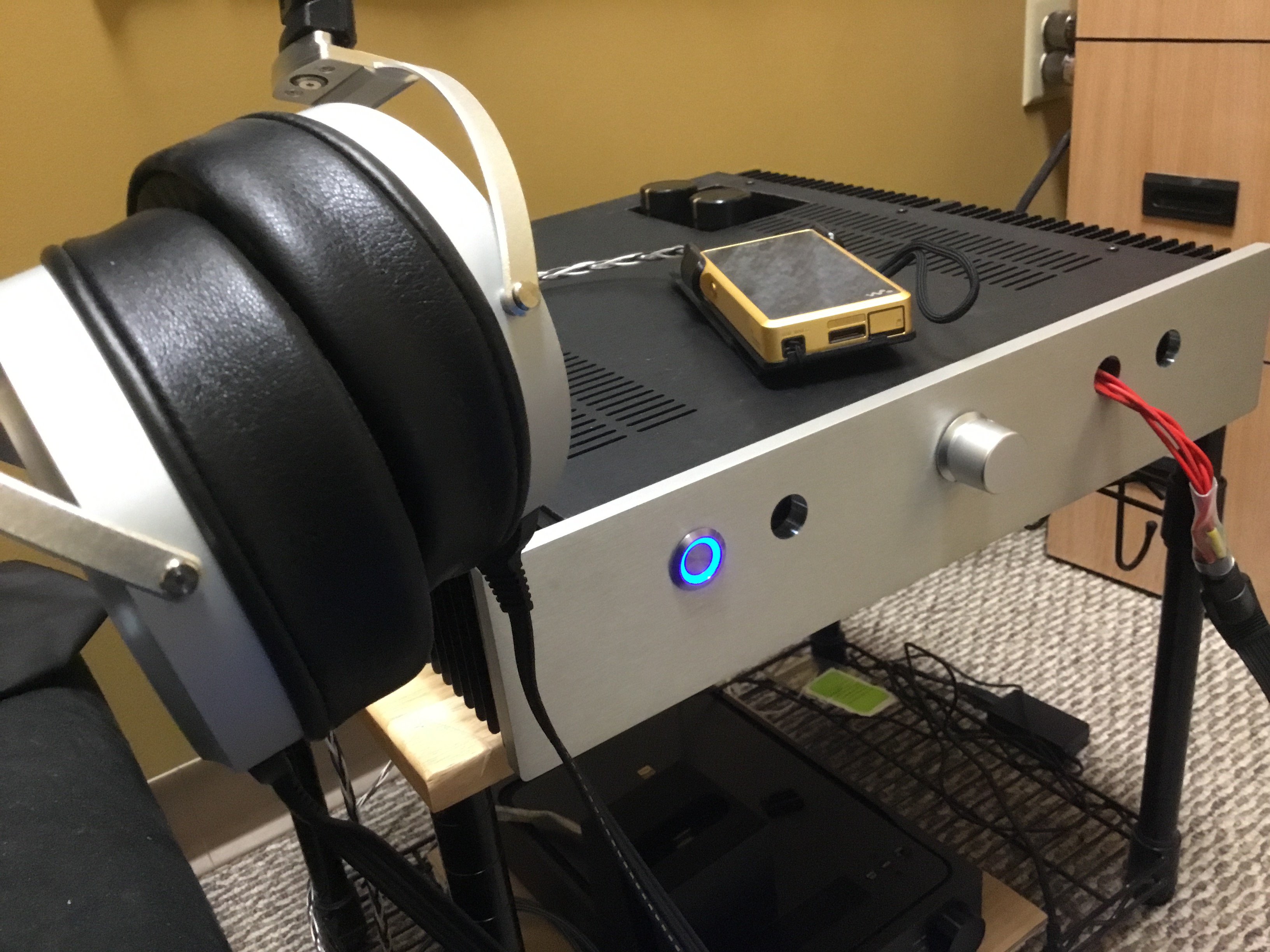
Thank you ! And yeah, I just have them spared laying around when my newphew did some cooking for his graphic cards. So extra doesn't hurt :). I can not believe how good this Carbon and 009 is. Approaching my endgame !

-
Yay! I got music ! I retuned the amp after 30-40 min where the offset drift back and forth instead of cold start. Bias 585V offset 15.75 Balance 200-300 mV current is around 17-18mA ! Playing it safe i only need to wait for all my sockets and clean up this wires otherwise it is healthy and pumpy thank you Kevin, John, Manuel, Soren, and all who have helped me to make this happen ! Love, joy and cheer! I can not appreciate Kevin enough for sharing this wonderful build which makes my dream of an endgame rig happened!
-
I see, so this is one way to help more securely tuning the current down / up as well. Another lesson updated. Thank you so much sir. the above scenario was my finding that either 10007 was being hung weirdly...or my 10m90s is fried. after tracing and making sure the relative components values to 10007 were all up to task, so 10007 is ok. So I tried to adjust again but nothing moved compare to my working board. This can only means 10m90s is fried. Waiting on new part to replace it i can confirm that if it is on amp board and measured below 0.2... or less than 400 Ohms in the board then it is dead. Removed it and it still measure 0.1 something *update* if the 10m90s is at 0.25 V measured on the board, it still kicking. But it is half dead. After I replaced the non working board, now it read 0.53V. I replaced the other one as well. now my balance is 330mv and offset is 18V. Will drop in opto Servo and check again tomorrow before test listening
-
Got 22.6-22.7 mA ? That means it probably is working like you said. Now 10007 to the 100R voltage is 1.5V. This is probably why the G R and V is measured different. The other board has 0.6 in the similar place. There is something to hang the 10007 this way >.<
-
The problem is that reading off board is different than on board :(. I tried measure the 1k R and it also measure 140ohm, the exact amount of the G/S
-
Is there a way to tell if 10m90s is bad ? Q26. I burned the 1k R, now the Q26 measure different than The rest
-
Finally ! She is up. Sir ! You have hit the jackpot!!!! I went through all bipolar trans and reflow it to just immediately realized that the PTZA06 was a bit floating on the solder. This explained why the R50K was being overloaded and the rest of it didn't click phewww....I thank you so much ! Now onto the trimming and current offset, balances
-
I still don't know what caused this 50k to burn-out don't want to fire it up again. i have all negative and positive reading as -457 and +457 then -14.96 and +14.96. There is nothing wrong with pSU. Bias testpoint runs 576V. More finding: after leaving everything overnight, the working Amp board has these transistors measured very similar to the none working one. All diodes are in checks, resistors on the non working one is a bit out of place such as 200kohm = 194 Kohm instead and while the working board has 199.8 k-Ohm measured. Should I replace this R too ? Or what am I missing ? Voltage drops across the bipolar transistors and diodes are similar on both boards, however >_<. The 50k Resistor was burned out slowly, so there was some overloaded current somewhere ? LED on pZTA56 did not light up
-
Yes, all boards GRD are into 1 star ground, or did I do it wrong ? Split PsU on both negative and positive
-
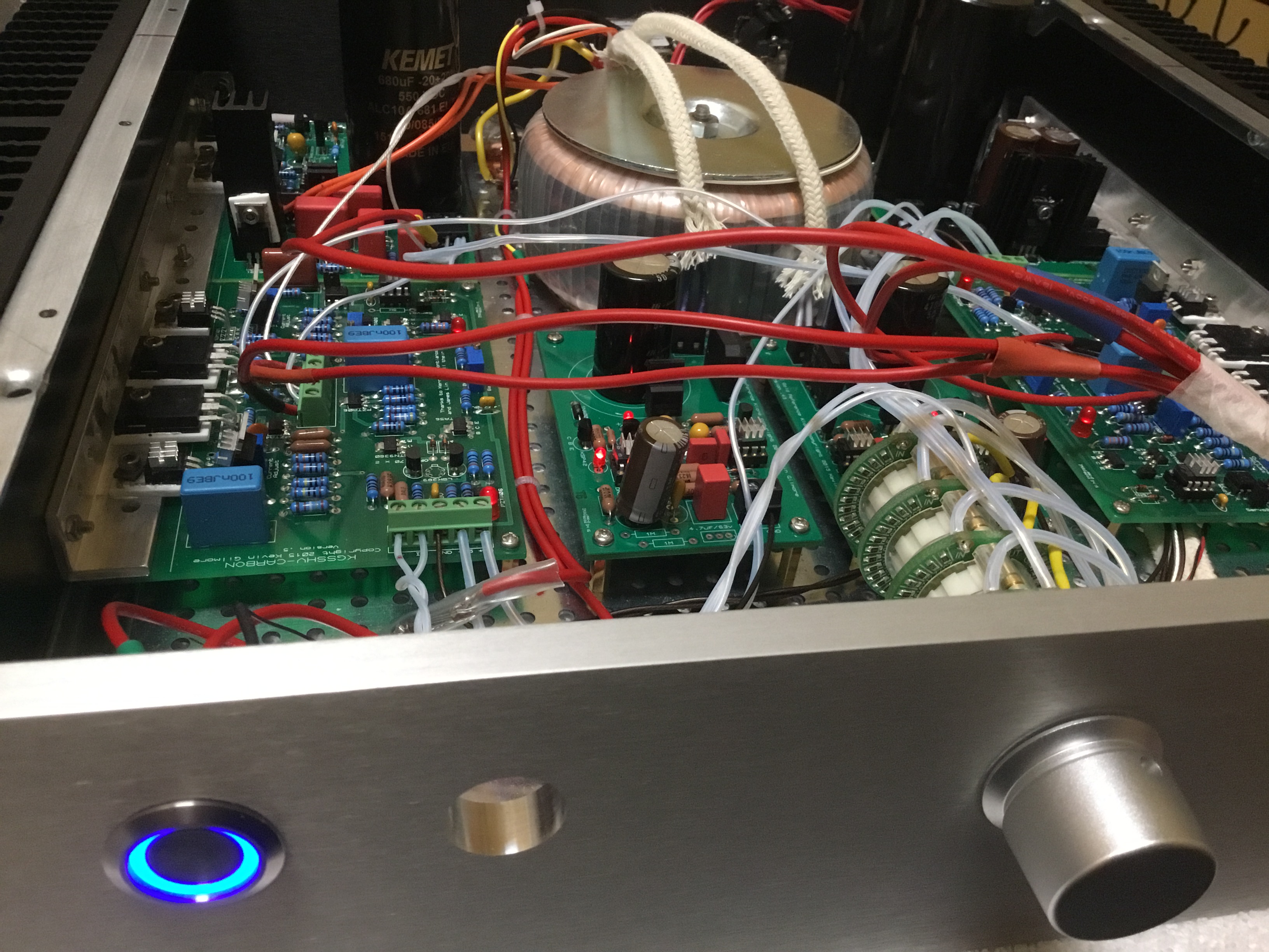
Yes sir, I did wired the 400+ to positive and 400- to negative, and the same as 15+ to positive and 15- to negative i replaced the 50k ohm resistor but have not yet to fire this board up as I know the problem has not been found. Pzta56 and stn9360 are in OL but resistance from B to C is fine reading. My guess is that something just doesn't open up this drive circuit at these guys https://imageshack.com/i/pmescTwGj https://imageshack.com/i/pmyzg54jj this 50K in the middle row and above pzta56 is the one that got shot. It burned so ever slightly that it only get slightly browned out, the resistance still measured up...the LED is not on. My other board is on just fine Measured the Voltage at O- and O+ To ground and each of them was 430+ or something when I did not realize it was being burned....measured both O- to O+ and it was almost 830+V across. https://imageshack.com/i/pmqtbe95j
-
HV is running 457 each side and LV 14.96 each side
-
Thanks Joa, I will need to check again and again tomorrow to see if it was perhap,caused by the faulty bipolar trans that fried that line. What else could cause the PZTA56 to get fried if not faulty from the Source as DOA ? Any ideas also joa, you are making SMD style ? Will there be spare boards ?
-
Both PZTA 56 is also not working >_<
-
So I fired it up, everything works, but one of my amp board is not working as only 1 led is on, the second led on the HV is not on :(. Anyone has any clues ? I think I smell something and...50k resistor is burned out
-
Thank you so much to I have successfully adjusted the current using your method. I have made out a picture here for future people needs https://imageshack.com/i/plNJXzaHj
-
Great! Thank you for the confirmations ! It is horrible to be lacking only 1 thermal alloy and it washer to complete the HV lol!
-
I thought I only need Low voltage to be able to adjust the current, offset, and balances trims ?