ericj
-
Posts
40 -
Joined
-
Last visited
Content Type
Profiles
Forums
Events
Everything posted by ericj
-
Aliexpress r-core turned up. It will fit between the tubes and even the original capacitors in the vertical orientation. Barely. The primary is marked "0-115v-230v-CN" which is a little confusing compared to western transformer standards.If we were dealing with common western transformers, it would be reasonable to assume that there are two primary windings, and they should be wired in series for 230v or in parallel for 115v. But that is not the case. For whatever reason, the chinese trafo factories prefer autoformer style primaries, so the 0-115v part of the winding is beefy enough to supply the whole VA rating, and the 115-230v part is wound with smaller wire. "CN" is meant to be tied to the chassis / earth. So in my situation, i am folding over the 230v primary lead and securing it with heatshrink, in case i some day sell this amp to someone overseas - don't want to just cut it impossibly short like Stax would have. Undecided how i will deal with the CN lead yet. The next concern is that both of the secondary voltages have two windings as well, and the phase is not marked. I view this as a dereliction of duty. But at the same time, no western vendor seems to have a similarly equipped transformer on the shelf, let alone at such a reasonable price. So the 220v secondaries have to be wired in parallel, and you have to match phase for that. It's best, at this point, to connect all of the leads on the transformer to terminal blocks. So they aren't just flapping around in the breeze and potentially shocking you or shorting to each other. Also, if you're a cheap bastard like me, sometimes you scavenge from broken junk. In north america, some small appliances - particularly fans for some reason - have cords that have an integrated fuse in the plug. Combine that with an inline cord-mounted power switch and a terminal block, maybe some wire ferrules, and you have a reasonably safe line cord for experiments. Anyway. Connect the secondaries to a terminal block and add a jumper between one lead from one secondary and one lead from the other, and measure the AC voltage between the leads that are not jumpered. If you measure roughly the sum of the volts of those secondaries, that means that you have connected them positive-negative-positive-negative (or reverse of that), so you can mark the first and third leads in that configuration as being the same phase. If you measure roughly 0 volts, that means you have connected them positive-negative-negative-positive (or the reverse of that), so you can mark the first and fourth leads as being the same phase. Works the same for the 6.3v secondaries of course. If you have a need to know whether dissimilar secondaries have the same phase or need to match phase to the primary, it's best to have an oscilloscope so that you can actually see the difference between positive and negative phases, but i expect that in this application we don't really need to know that much information. I think i will cut the 220v secondaries short, and solder them in parallel with one set of wires to connect to the power board. I may wire the 6.3v secondaries directly to the tube sockets. I will have to read up on the pros and cons of letting the heaters float vs. tying one side to 0vdc directly or through a resistor. The published schematic shows one side of the heater power tied to 0vdc.
-
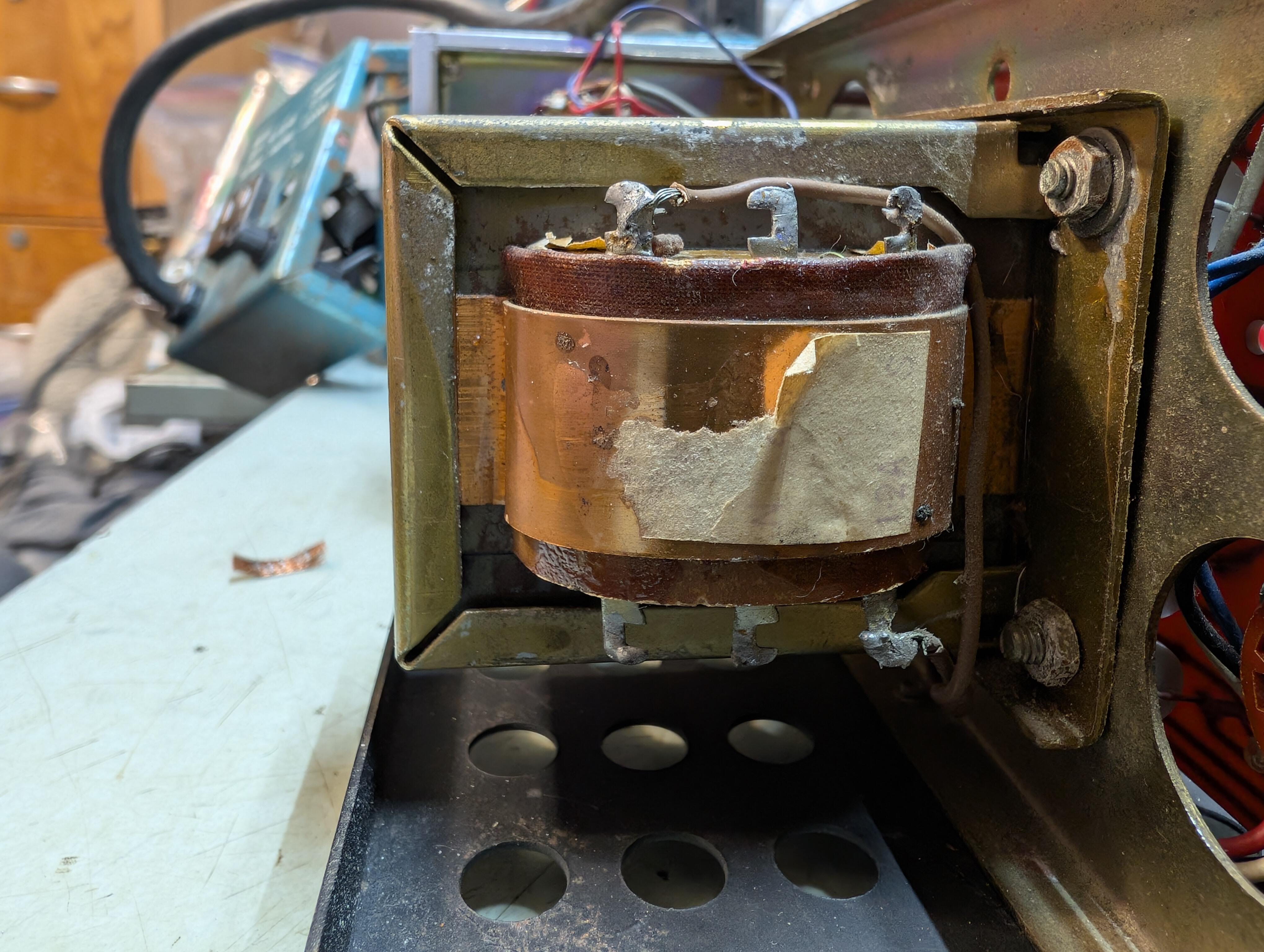
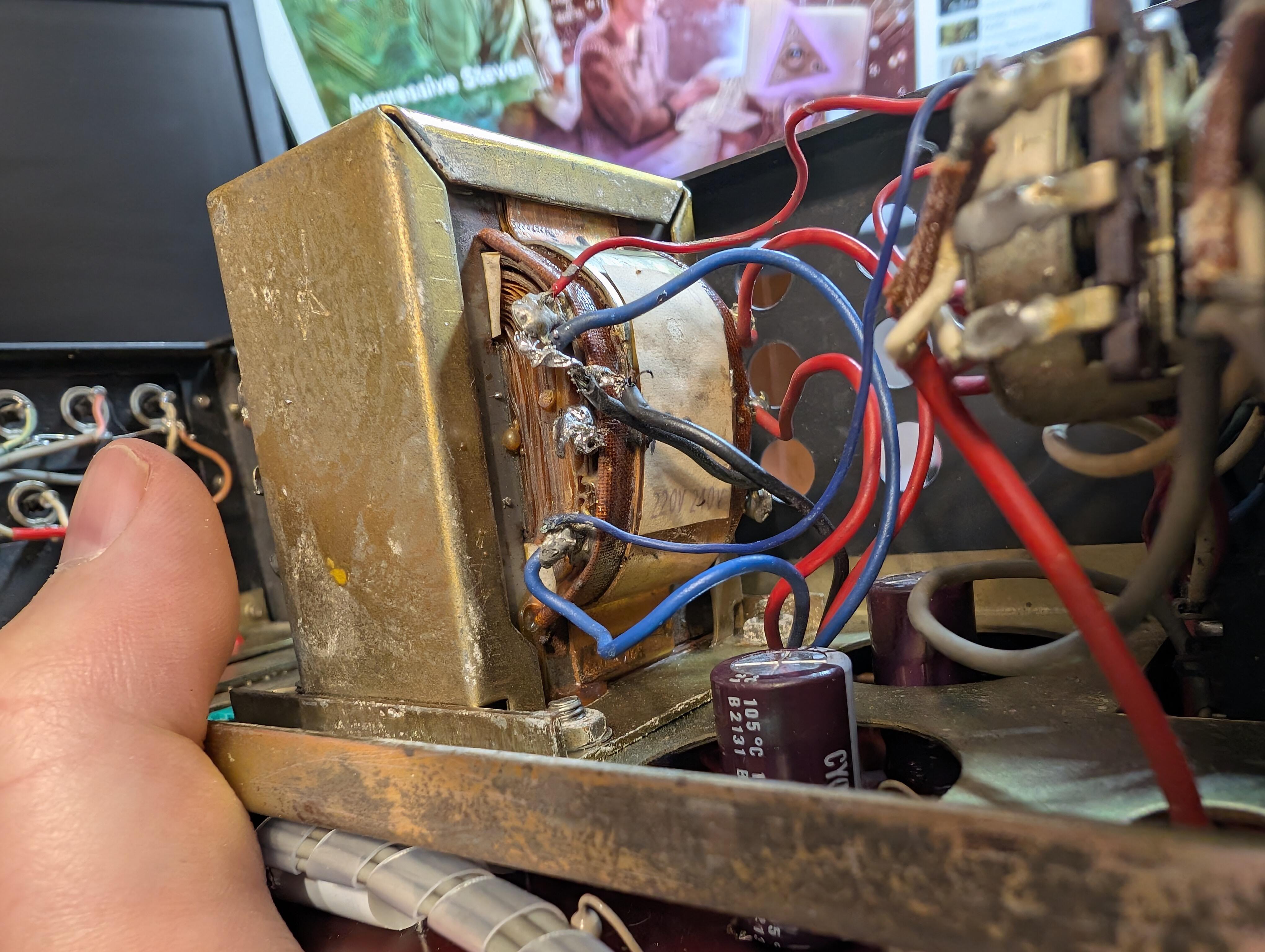
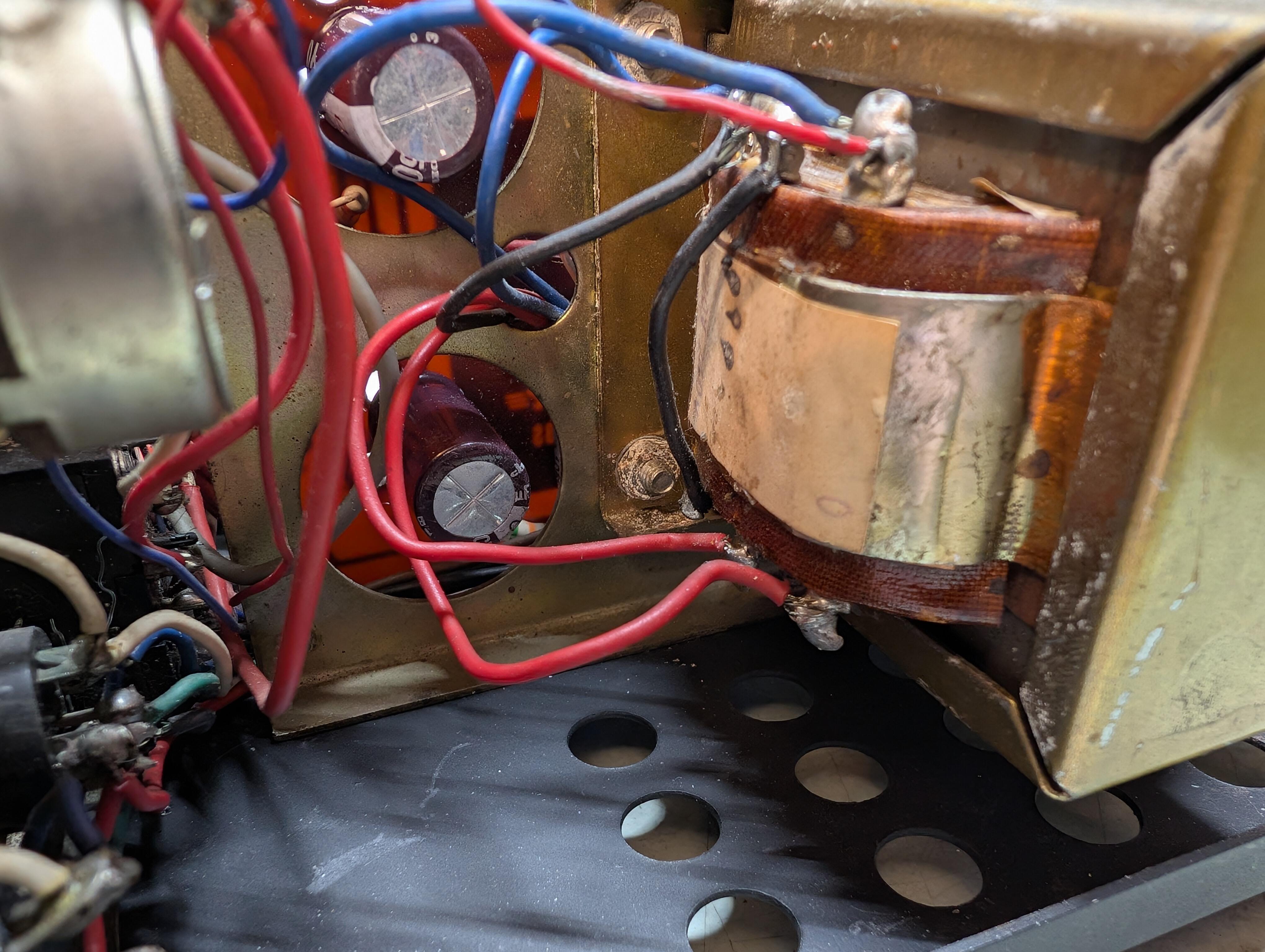
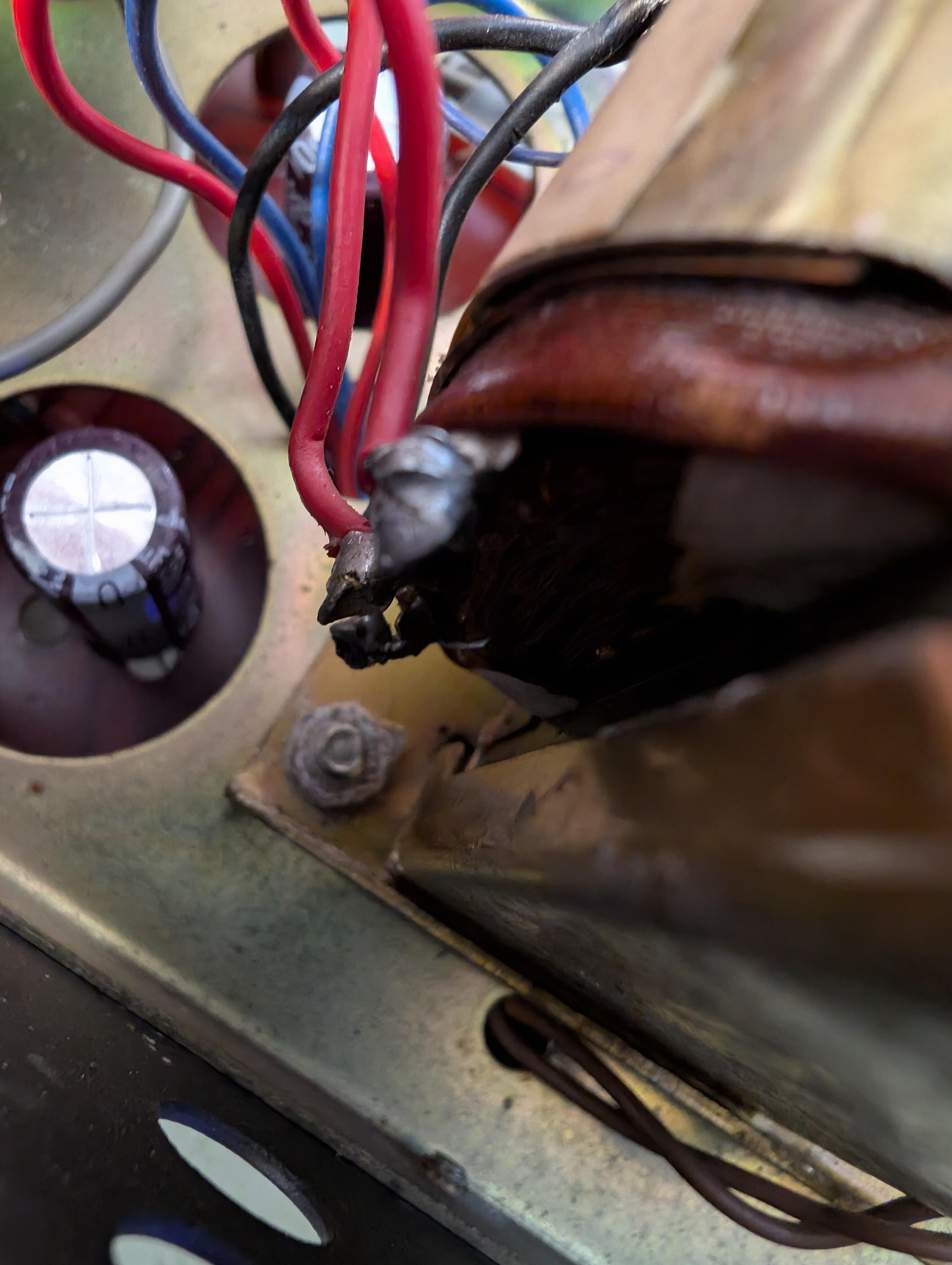
OK, my transformer is toast. But i don't understand exactly what happened. Again, this was purchased as-is untested from someone who didn't know anything about it. I'm only getting 3.4vac on the heater winding and about 135v on the b+ winding. Investigating the primary side, only one of the unused lugs has a connection, and it seems to be about 8 ohms (dc) past the end of how it is currently wired. So my surmise is that it is configured for 100v and it is possible to move a wire to the other lug and power it from 117v. The heater winding has a center tap that is connected to 0vdc, which seems totally reasonable to me. The wire to ground from that center tap was pretty gnarly with some of the insulation at the end melted through and some loose filaments, as though someone who doesn't believe in flux was monkeying with it. The weird part is an additional black wire going from the heater CT to a lug next to the b+ wires. Hard to see in my crappy photos, but that lug did have a connection to something in the windings. If i disconnect it from the CT, it is an open circuit to all other lugs as well as the core and shield. And there are some black marks on the paper label underneath it that may be burn marks? So my guess is that perhaps the b+ winding on this unit had a center tap as well, and someone was trying to convert it from 100vac to 117vac operation and mistakenly tied half of the b+ winding to 0vdc, causing it to burn out. Though that doesn't explain the low heater voltage. I've ordered that aliexpress r-core because i refuse to recognize the sunk costs fallacy. I'll also order some 10mm or 12mm diameter b+ caps that can be laid against the power board to make room for the r-core.

-
-
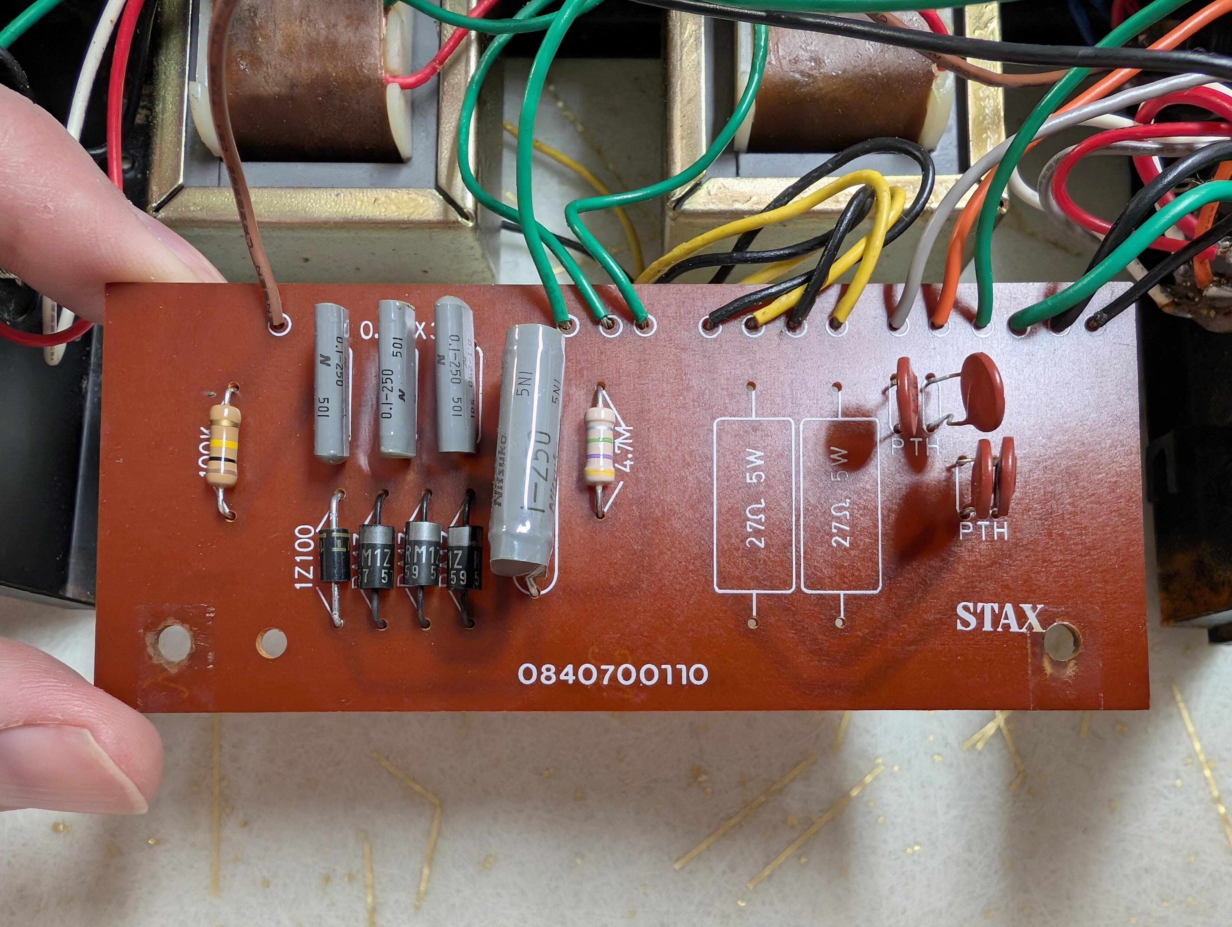
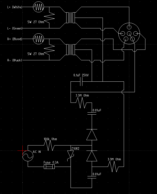
OK, picked up a 7/SB on ebay for $50 + ship. Which was fair because this poor thing has had a hard life. There's rust, and wax melted out of the transformers. Yes, it's a unidirectional zener, marked 1Z100. My guess is that the current equivalent is ZY100 which will produce a voltage of about 83v at best, then 3x cockroft-walton and a 1uf reserve cap *before rather than after the ballast resistor, and the ballast resistor is 4.7M rather than the 2.2 or 3.3 specified in some of the wall-powered schematics. I'm pretty sure I've seen pictures of a 7/SB that had an additional transformer in the bias circuit but not this one, and the board looks identical to a gutshot of an SRD-6/SB i saw recently. I still think it's weird that i have yet to find a /SB official schematic. *shrug* maybe they never published one. Now i wonder what's in the fairly rare SRD-7/SBMK2.
-
What utility does a low-pass filter with an Fc of 312khz have in an AF circuit? Particularly after a transformer that has windings that are most likely unable to efficiently pass signals much higher than 15khz?
-
If that drawing is correct, it's not the only way the SRD-6/SB has been made. Count the components.
-
Tell me what green brown red gold means to you and how it differs from output safety resistors on later products. We don't deserve to know why but these matter. splice them into the output wires and seal with heatshrink - the traces on the sra-3s mainboard are far too fragile to support extra components.
-
The SRD-5 does have them. Here's the schematic. Do you want to see pictures of the board in my SRD-5?
-
OK. Did i claim to? I can see where a mosfet shorting out in a solid state amp would be very bad. That's not a typical failure mode for a tube. Stax used one 5k1 output resistor per channel in the SRD-5 but not in the 4, 6, or 7. I've seen threads where you said you wouldn't put them in a transformer energizer. So, enlighten us.
-
I think 5.1k safety resistors would serve no purpose in this amp. There are already a 51k resistor and a capacitor between b+ ("A") and the outputs. Mouser has replacement slots. I ordered 1. They have 10 left. No idea if they would re-stock after they are gone - nobody else seems to have them in stock. https://mou.sr/3D1kgOo Good glue and a zip tie seems to be able to repair cracked slots. I repaired both of mine that were cracked at the bottom and i figure the top end will crack some day too. There's very little chance that i will ever have a use for the phono preamp. It's fun to imagine what else you might fit into that spot. Crossfade filter? would need its own preamp. Should be possible to rewire the rotary switch if you simply wanted multiple inputs. Speaking of, the RCA connectors on mine are in poor shape as I am sure are others. I'm sure there was a time when you could just buy a panel with four RCAs on it from any vendor but not anymore. deoxit and some elbow grease is probably enough but, we can do better. Due to the way it is manufactured, most RCA jacks won't mount to the existing panel - holes are too big. Maybe these jacks which are secured with an external nut can replace carefully removed 50+ year old tin jacks: https://www.aliexpress.us/item/3256805498973752.html I ordered a pair. I also have basic CAD skills and a laser that will cut plywood, so it would be no big deal to manufacture replacement panels to accept contemporary jacks.
-
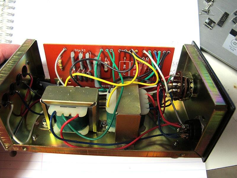
In theory, this r-core could work.Might have to reorient the main power filter caps to make space for it. I'm pretty sure if i read correctly it has a pair of 220v 50ma and a pair of 6.3v 0.8a. https://www.aliexpress.us/item/2251832814206073.html Edit: I checked. It'll fit in the chassis in either orientation but it *will block the holes for the original main filter caps. Modern caps are no bigger in diameter than the original axial caps on the board, so you can mount them flat to the board and use that space. With 2x800mA 6.3v it also has plenty of heater current for ecc99 and probably enough for 6n6p. I know Spritzer says that there's no place for hot glue in electronics, but if you use the high-temperature stuff it's Firm Enough to hold stuff even in adverse environments, and with a squirt of isopropyl it will give up and come off so I don't see the downside to using it to secure stuff.
-
Y'all are making me worry i need to check the transformer windings in mine. I never even plugged it in. I'll check tomorrow. Probably no easy replacement for the transformer. You could get edcor to make one but it might be more expensive than having the original rewound. Or you could use two transformers, or something.
-
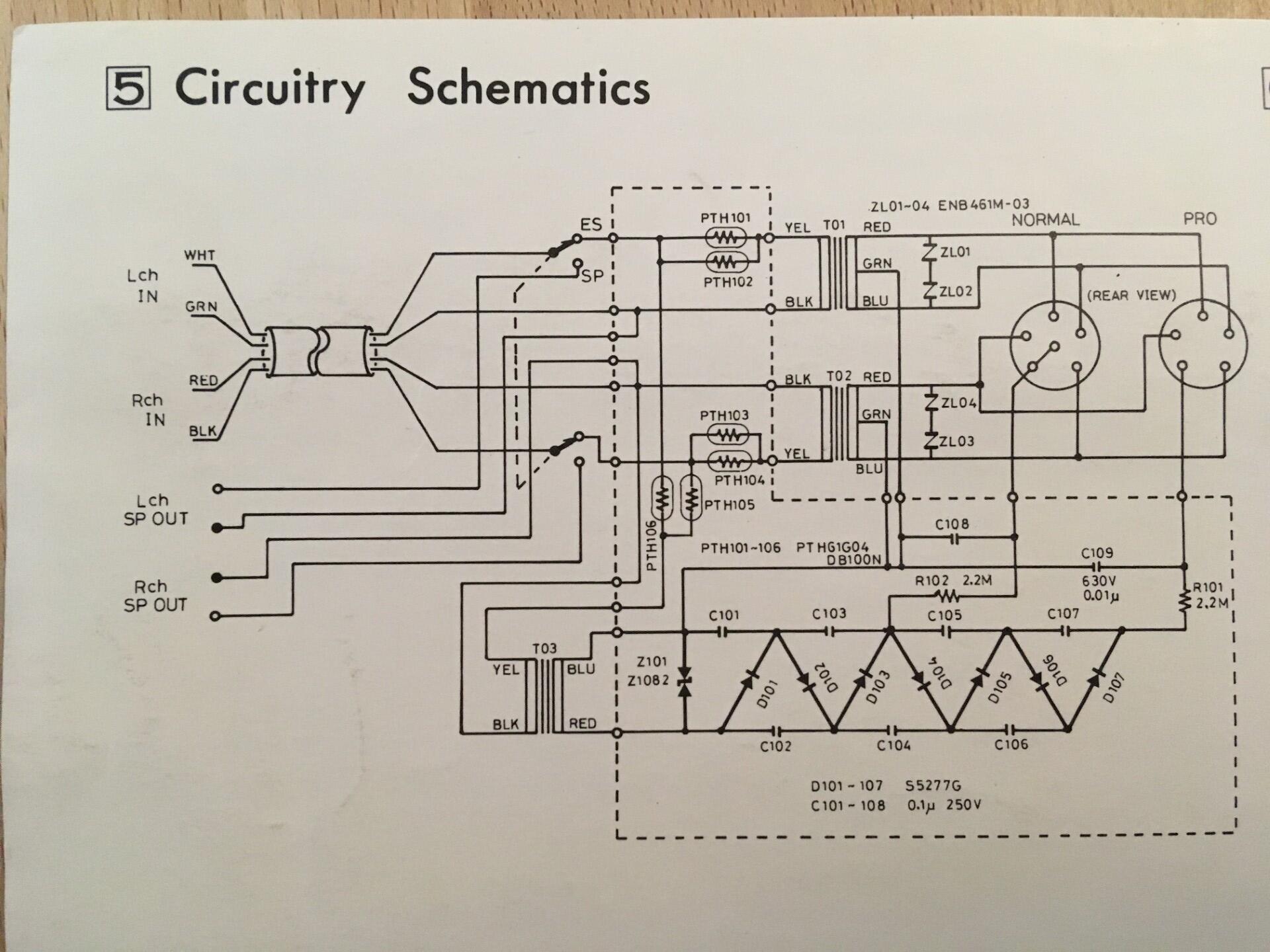
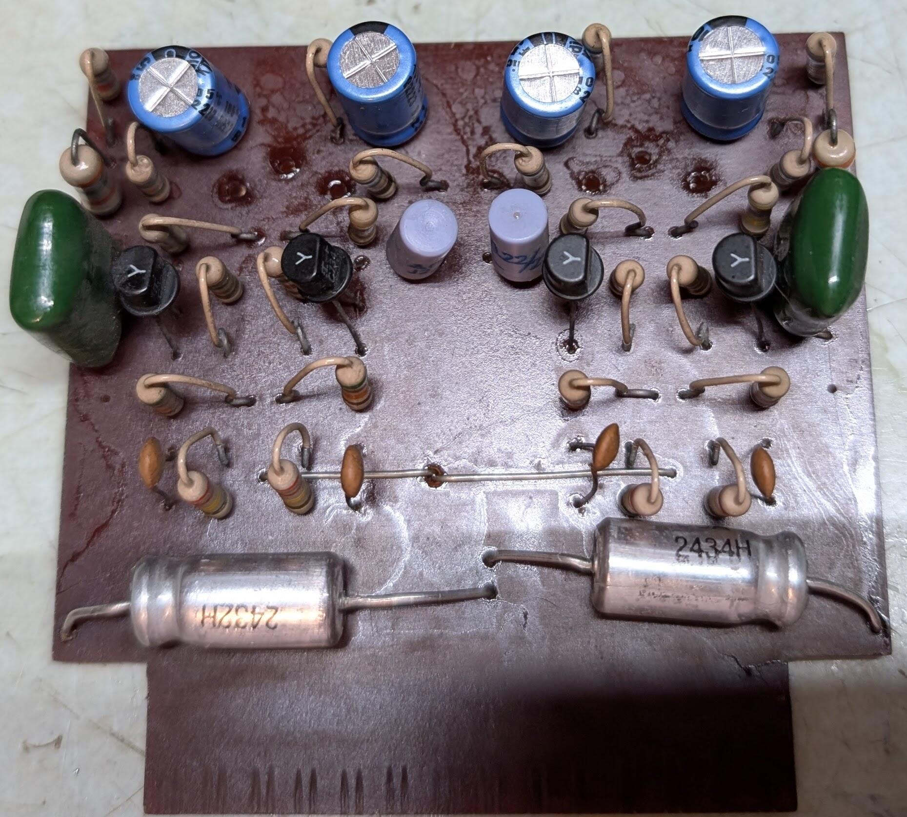
On to the shaded portion, the actual amplifier. The 0.05uf caps are the large films on the main board. It's likely a good idea to increase these to 0.22uf 630v polypropylene. The 0.2uf film caps on the driver board should be upgraded to 0.47uf polypropylene. There are also 0.22uf electrolytics near the center of the board, I replaced those with 0.22uf Wima polypropylene. I think it's possible that both of these should be upgraded but i am unclear on that, and would welcome input on the matter. One of them is clearly an input coupling cap, the other goes from the base of a transistor to ground. The 10pf bypass caps shown on the schematic were 5pf ceramic discs in my unit. Spritzer recommends upgrading to silver mica 10pf which sounds reasonable to me, though there's probably no reason not to use polypropylene. The back to back 100uf 6.3v can be replaced with a single 100uf bipolar radial cap. The unused position for each channel should be jumpered. The trimpots are probably pretty crusty. Piher "15mm" horizontal-adjustment trimmers fit this position, fwiw. Bourns probably makes a similar trimmer. The 33uf 50v 105c axials you can get from Mouser are listed as Vishay, and what you get is a USA-made Sprague cap in clear heat shrink like it was made in the early 80s or something. I'm sure they work but, whaa? I'm not the first person to buy these. I wonder if they are ancient stock or not. It may be worth the hassle of adapting a radial cap here. 5.1k safety resistors can be added to the outputs per Spritzer's recommendation. $1.70 at Mouser gets you qty10 TE Connectivity RR03J5K1TB - 5.1k 5% 3W 750v rated metal film. I am not yet sure where best to mount these. Having read some threads about other stax tube amps, i think it *may be possible to adapt the circuit to accept ECC99 or 6N6P(i), but the heater current on those is somewhat higher - 800mA for the ECC99 and 900mA for the 6N6P vs. 600mA for the 6fq7 / 6cg7 and the transformer might not be up to it.
-
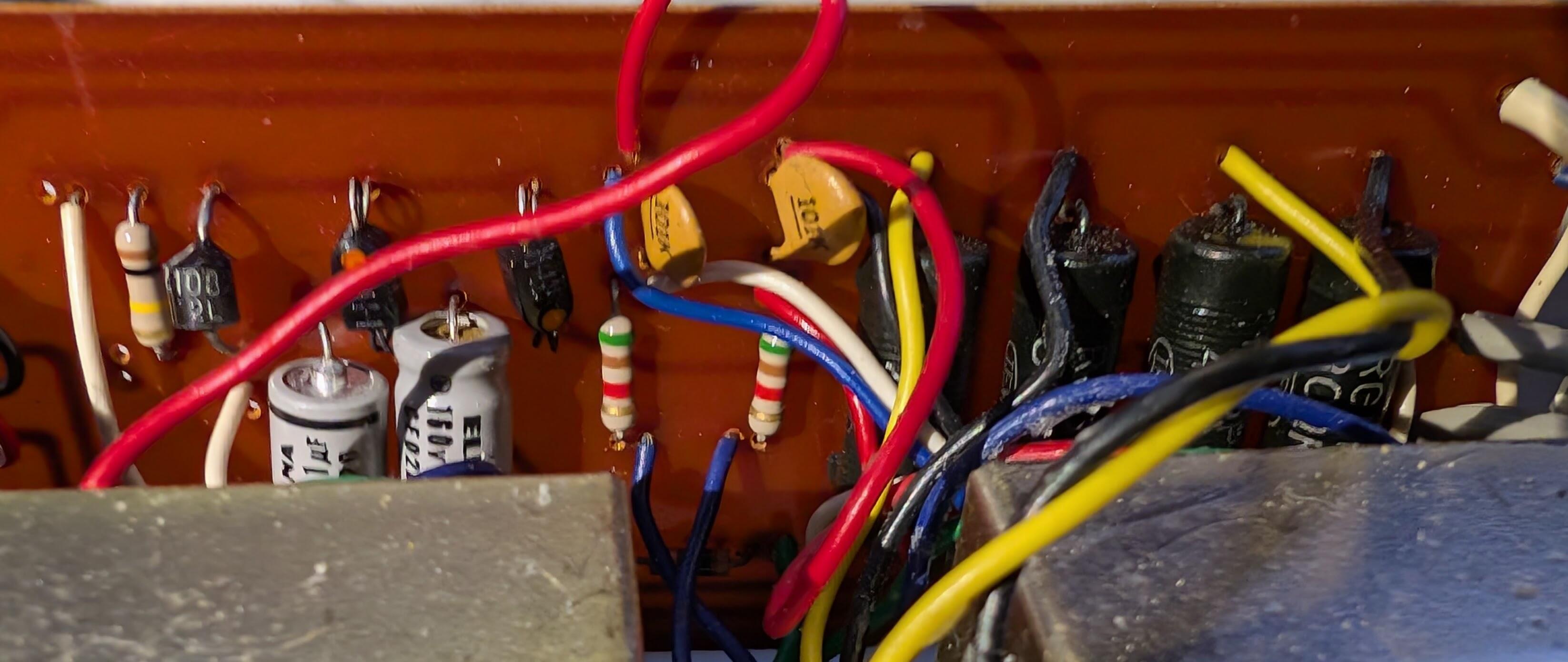
So as to stop spamming the stax thread, and get everything in one place. I recently got a ripping great deal on an SRA-3S in unknown condition. And since all of these are at least 50 years old, there is much to go through. There are some existing resources to link, and I will come back and add more as i scrape 'em together: It's a shame there are no component designations on the boards or schematic, so we'll go ahead and muddle through without them. Maybe I'll annotate some images. The area in the red box is the phono preamp. It's not much of a preamp. I hear you can pull the board and leave it out. An enterprising nerd could build a better phono preamp to plug into the same slot. The modern replacement for all transistors in this box is the KSC1845. These are available from Mouser and other 1st tier vendors so there is no reason to look for them from secondary sources. The pinout is reversed. If one of the four on the driver board is bad you should probably replace all of them. I suppose i should put together a complete BOM at some point. You will need to remove the bottom of the case and desolder the RCA connectors on the back in order to angle the main board out to work on it. Starting with the power supply in the area in the blue box. The vintage diodes should be replaced with 1n4007, uf4007, or similar. I used BYV95C fast soft recovery rectifiers because i have some. Probably doesn't make a difference what you use here as long as it's a high voltage rectifier. My unit actually had 22uf 350v caps in the power supply. I installed 39uf 350v. They are comically small compared to the original caps and it may be wise to anchor them with some hot glue. I used Nichcon UCY2V390MHD, qty2. I am not sure if it is wise or useful to go big here. Axial caps are getting harder to find and there are few choices. It might be totally reasonable to get radial caps and attach wire to the positive lead, maybe wrap it in heatshrink or plastic tubing of some kind. For the 30uf 150v caps, my unit actually had 22uf. Which i foolishly ordered 22uf replacements for. They were expensive and about the same physical size. I'm thinking about ordering some 33uf long-life radials and adapting them however it will work.
-
That sounds reasonable, maybe in the diy subforum?
-
I would just leave the ties in place. There's no downside. The only reason I'm not tying the other end is because that might just mean it breaks somewhere harder to fix.
-
Ah, i used ~22awg solid copper and twisted the ends until it closed the sides with the superglue. I guess the drawer full of wire was closer than the container of zip ties. I kinda feel like cyanoacrylates aren't what they used to be -- "bonds instantly" used to mean i didn't have to clamp it for half an hour. sigh. I don't see evidence that there was foam holding them in at any point but i have some dense foam i will install. All of the resistors in my unit look fine to me. Nothing ran hot enough to show. I suppose i should lift a leg of the one big carbon comp resistor to see if it is still in spec. Can anyone fill me in on the adjustment procedure for the trimpots?
-
When i pulled the main board out of my sra-3s further so i could work on it more comfortably i finally noticed that the reason the cards fell out in shipping was probably the fact that both slots were cracked at the bottom end. I've fixed them with superglue and wire ties, but it looks like you can still get a direct replacement: https://mou.sr/411lhxZ
-
So while I'm here, i have the ksc1845 transistors that are the recommend current production replacement for all of the transistors in the sra-3s. Should i just replace the driver transistors on principle because they are likely lower-noise? There is very little risk that i will ever use the phono preamp.
-
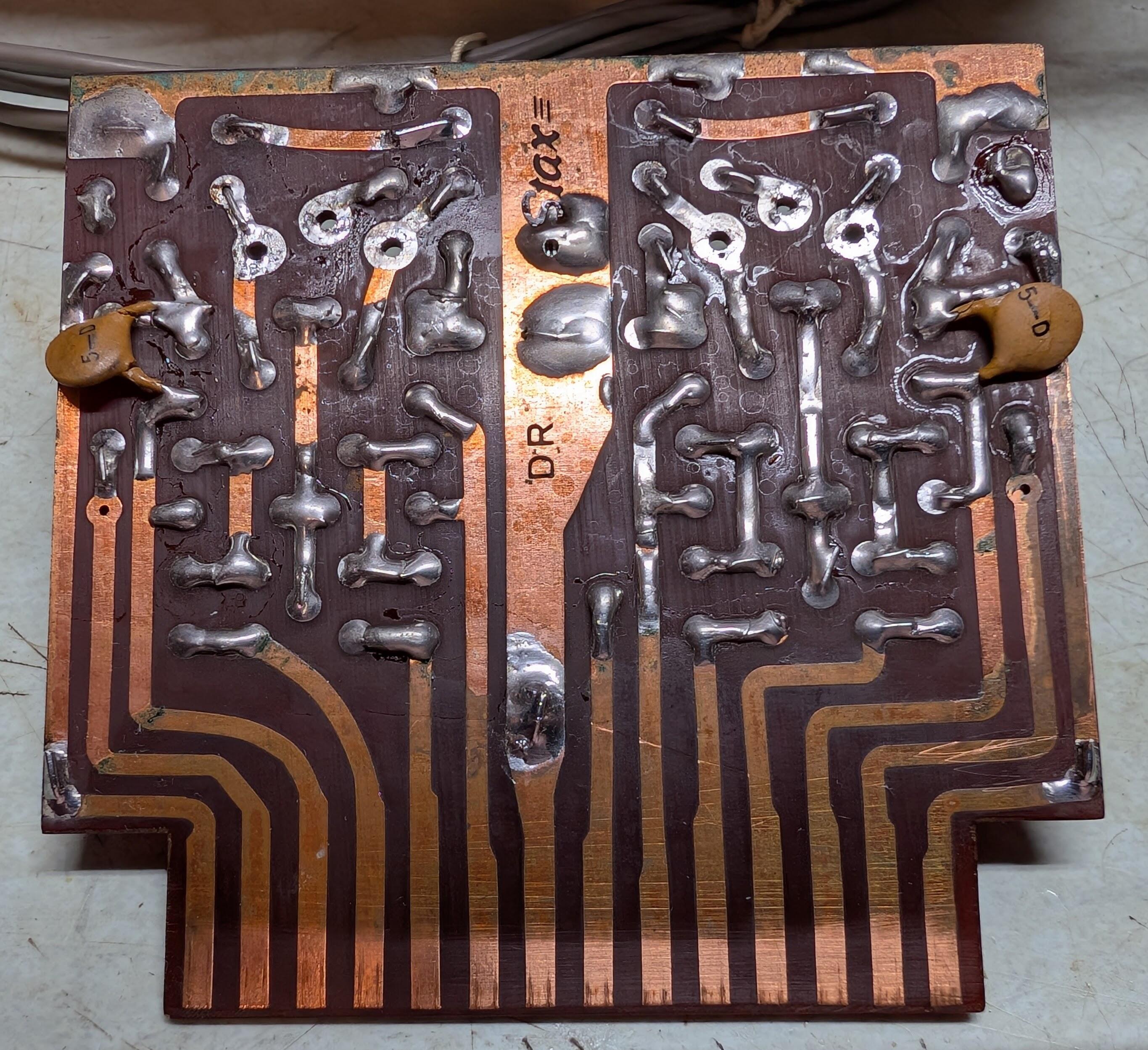
I'm updating the SRA-3S i bought recently. It was pretty cheap ($65) in as-is condition untested, so they said. I've never powered it up. I read through the thread in the diy subforum and saw Spritzer's recommendations. Looking at my driver board, I think I don't have enough capacitors? There are four small ceramics that just have a "5" on them which i presume to be 5pf, and appear to be in the positions in the schematic that specify 10pf. I'm getting some mica caps to replace those. But where are the four 0.05uf caps that he recommends to upgrade to 0.22uf? There are two ceramic blobs on the back marked "5-D" that i don't really understand, unless there were supposed to be two more of them? I suppose i should desolder one and measure it. The trimpots were removed for replacement. EDIT: Nevermind, I'm a dumbass, they're on the main board.
-
Got my SRD-5. It looks like an SRD-7 board would actually swap right in, despite the much smaller chassis. The SRD-4 (and 6, afaik) are a little trickier to squeeze the full circuit into but i think it'll work. There's maybe 46mm between the mounting hole centers and the top of the enclosure. No fuse at all in the SRD-5 so i added a spot for one on the board. Tight layout, so it's a an 8mm diameter radial fuse, optional fuse holder.
-
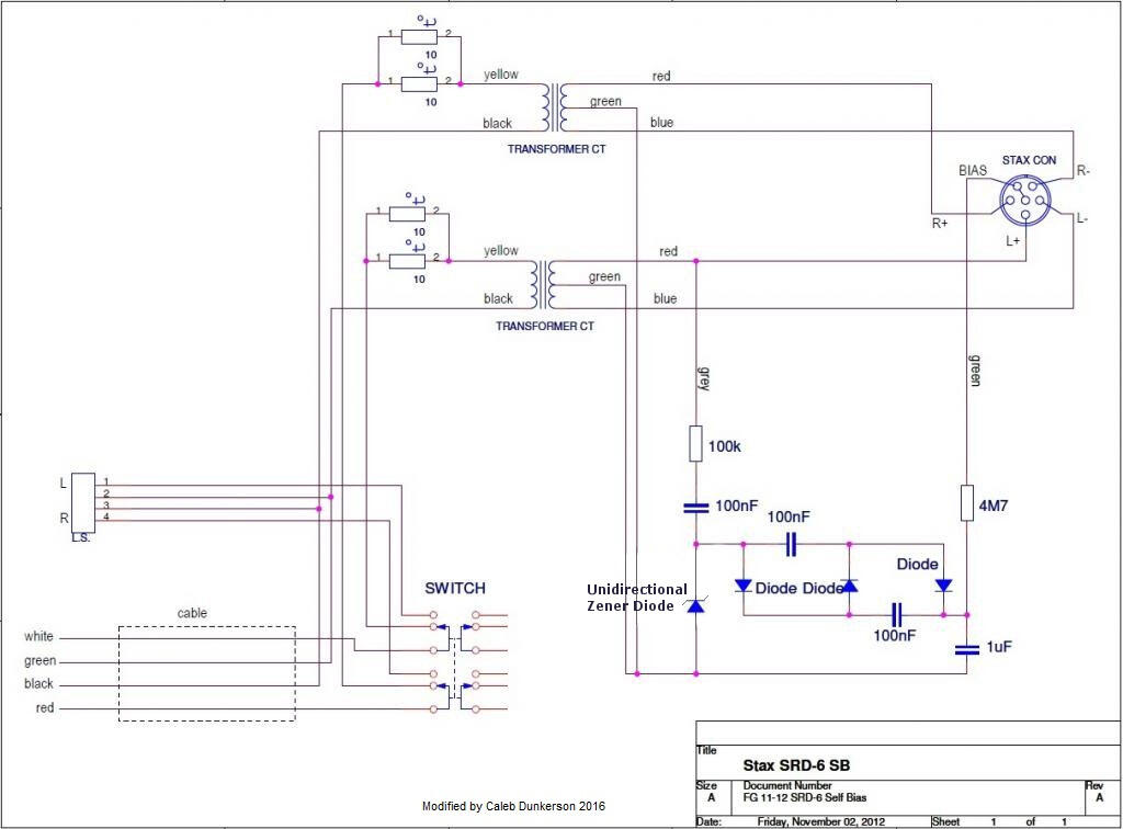
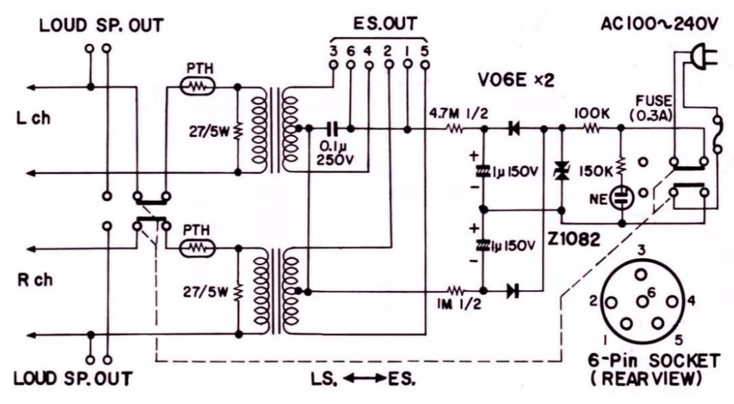
From another thread here, a drawing of the SRD-6/SB circuit. I am not too sure about this one. The 100nf cap between the 100k resistor from the transformer secondary and the zener seems wrong to me? But we may as well provide accommodation for this kind of modification.
-
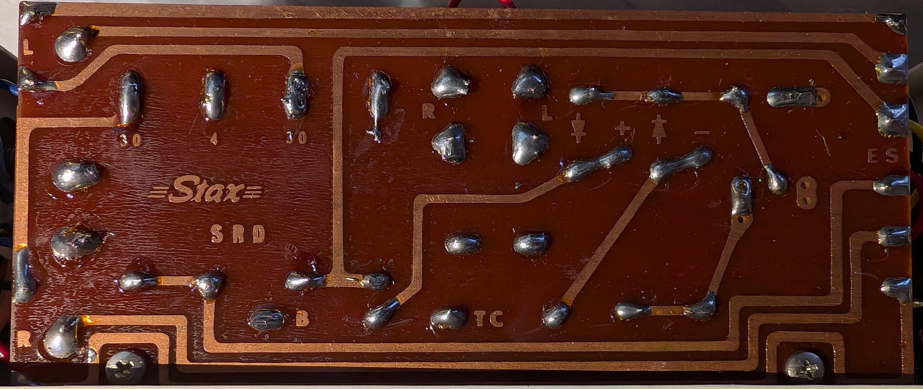
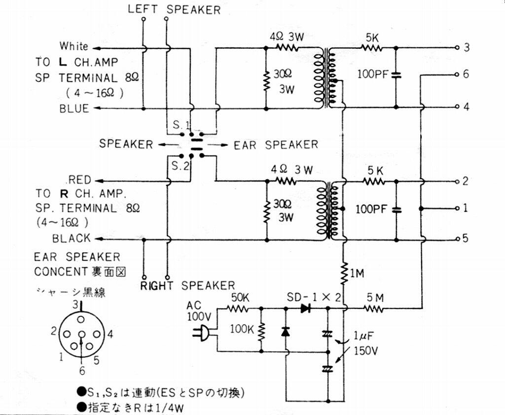
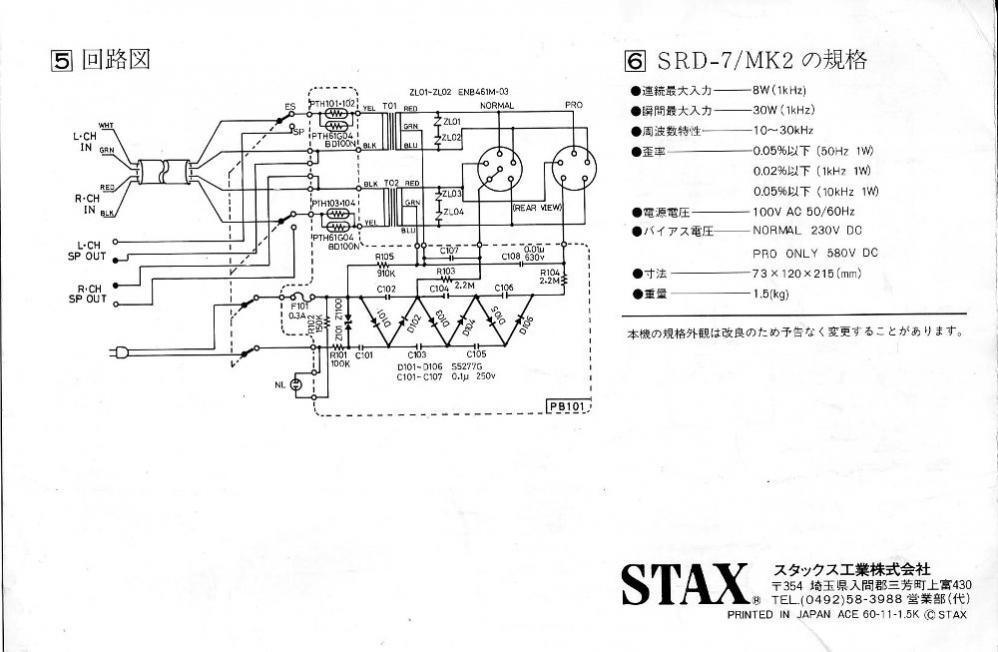
I could swear i had the whole schematic sheet for the original SRD-7 but i don't seem to have it at hand. Anyway, just the drawing of the SRD-7 schematic, SRD-7 Mk2 and SRD-5 official schematics below, and someone's hand drawn SRD-6 schematic. Notably the SRD-5 has 5k resistors on the outputs. I had sworn i saw spritzer or someone say they were only used in later amplifiers. At any rate these seem to be of not much important and will probably not be included. The 5, 6, and 7 all have a 30-ish ohm resistor across the transformer primary while the 7 Mk2 (and the 7 Pro) do not. My SRD-4 doesn't either. I have seen some people advocate for these to be present. I presume it is to provide an alternate path for ultrasonics. It seems like the board should support these, but the BOM should list them as optional. I'll make sure there is room to just harvest them from your original board, as there's a good possibility that the old Stax corp used nonmagnetic resistors. Haven't checked. A lot of people feel that the PTH devices are unnecessary and a potential source of distortion. The 5, 6, and 7 had 4.7-ohm PTH devices and the 7 Mk2 (and pro, and SRD-4!) have a pair of 10-ohm in parallel. Many people would prefer to just use a 4.7 ohm 5W resistor and be careful with the volume knob on their amplifier. Maybe new PTH devices are less noisy? I can't say i hear the distortion. I think perhaps the board should have options for both, perhaps overlaid so that it is impossible to install both of them. I have identified modern equivalents of the PTH devices. ZL01-ZL04 are MOVs. These are only found in the 7 Pro and 7 Mk2. A lot of early stats and trets had these inside the ear cup. I have heard that back in the day some people wondered if they were harming the sound somehow. I think the board should accommodate these and the BOM should specify that they are optional. There's some variation on the capacitors used in the voltage multiplier and based on prior discussions with spritzer and others i think we can just specify 0.1uf 250v, wima MKS4 is what i have been using so far. The 0.01uf cap between the transformer center taps and the bias is in some and not others, and there seems to be a consensus that they should be removed. Some schematics specify 4.7M or 5M for the bias resistor, some specify 2.2M. I am pretty sure the consensus is that 4.7M is the better value. A resistor that is specified for high voltage may be warranted here. It's not much more expensive than others from Mouser. The voltage multiplier diodes are nothing special, 1n4007 will be fine. There are reports of leaky diodes from china, so, use diodes from a major supplier. The zeners. In the official schematics that i have seen, they always use the symbol for a bidirectional zener, what is more commonly called a TVS diode these days. There is some confusion about these, but Semitec manufactured them until 2005 with that part number. There are modern equivalents, or we can use a pair of 100v zeners. Some people are saying that the SB energizers should use a unidirectional zener but i don't know what their logic is. At any rate, if upgrading a 5, 6, or 7, you have the option of harvesting the original component and using it on the new board, strapping a wire across the position for the other zener.
-
9 years ago i started tinkering with the idea of a board to upgrade both of my SRD-7 to SRD-7 MkII, and then eventually a lot of stuff in my life went sideways and the project got shelved with a lot of other stuff. It did not work! it kind of worked. I screwed up something in the way the voltage multiplier was hooked up to the extent that there was only 26vac across the zener. I re-drew it yesterday. It's possible that aliexpress 1n4007 diodes were a factor. I'll use uf4007 sourced from mouser for the next revision. I know this shouldn't be hard. I'm kinda dumb for a smart guy. Sometimes i get a brain cramp. At the time, 9 years ago, my only high-bias stats were my esp-950. It wasn't a high priority. I have other ways to listen. I seem to be diving back in, though I'm still a cheap bastard. Yesterday i received an SR-L300 w/ brand new pads w/ all the original packaging and documentation from Japan for $250 shipped. I think I'm still in no danger of ever owning any kind of omega. So i have a couple DIY amps, two SRD-7, an SRD-4, an SRD-X in pieces, and today i received an SRA-3S. The other day while i was revising my SRD-7 Mk2 board i decided to see whether it would fit inside the SRD-4 and yes it would, just needs different mounting holes. I would be tickled pink to turn it into some kind of SRD-4.73 Pro/SB. Not ideal, sure, but i am a strict adherent of Duke Ellington's law, plus it would be funny. I could also swap sockets between the SRD-4 and one of the SRD-7 so i have a legit 5 pin socket on the 7 and a legit 6 pin socket on the 4, and just make it a 6/sb with some modern adjustments. It looks to me like the SRD-4 and SRD-6 share the same chassis. The other night i bought an SRD-5 from someone on the auction site for $25 shipped. If i keep it small, I bet i can have a board that can be used to convert any stax energizer to modern, potentially high bias spec. Probably the early 80s low-dollar stax oem (magnavox, etc) boxes, maybe micro-seiki stuff and whatever else as well, wall or self bias. I don't have the patience for commerce so i am considering just publishing gerbers and BOM.