Blueman2
-
Posts
289 -
Joined
-
Last visited
Content Type
Profiles
Forums
Events
Everything posted by Blueman2
-
Well, after all of the adjustments mentioned, and after warming up for about 1 hour, I can say the amp is pretty much silent. My son, who has much better hearing than me, says he can still make out a hum, but it is really not bothersome. If I listen to the SRX-Plus with no music playing, and pull the headphone plug while wearing them, I can barely make out any difference. I am going to try different tubes when they come in this weekend, and see if that makes any difference, but I am a happer camper right now! EDIT: I installed a quad set of Penta Labs 12AT7's and that eliminated the remaining hum. Odd, because it was the output stage tube that I thought was causing the hum because when I swapped the 6SN7GTA's, the hum switched sides. More to come once I install a new set of Tung Sol's tomorrow when they arrive. Now, as to SRD-7 vs SRX-Plus, the winner is the SRX-Plus pretty clearly. Even when driven by a very high quality big $$$ power amp, the SRD-7 has a rather hollow and metalic tone to it compared to the richer, fuller, warmer SRX-Plus. Interestingly, when I put my 507's on the SRD-7 and my son's 407's on the SRX-Plus, the 2 compared pretty well. So the 507s are a similar step up from the 407s as the SRX-Plus is to the SRD-7. I will keep the SRD-7 as a backup, but the SRX-Plus is now my daily driver. One other modification I would like to make is to add a delay relay to the headspeaker output, which keeps open circuit for 10 seconds and then connects the L+ and R+ output lines to the jack. Any idea of where I could source such an item?
-
Great suggestions from JimL, mwl168 and jose. I forgot to tie the case to ground (duh!) so did that. I have tied PSU, AMP, case, and transformer shield to earth ground. I also cleaned the pins of all the tubes with electronics grade alcohol and steel wool. And per JimL, since I am running 370V PSU B+, I adjusted input current sink to .123V across the test resistor (I am running 300K plate resistor). I am now down to a very quiet but perceptible hum when not playing any music on the input. Of course, the hum goes away (from a perception standpoint) when playing music even at low levels. Comes from both channel, but is stronger on the right channel. When I get my new tubes, I will see if those make a difference. I have not installed the volume control yet. I assume that goes on the INPUT side, right? I test installed it initially but it created quite a bit more hum, which varied by position of the volume control. In reality, I am not sure I even need a volume control since since my supply devices all have them already. I am now going to do a side by side test with my SRD-7 setup to see what the quality difference is.
-
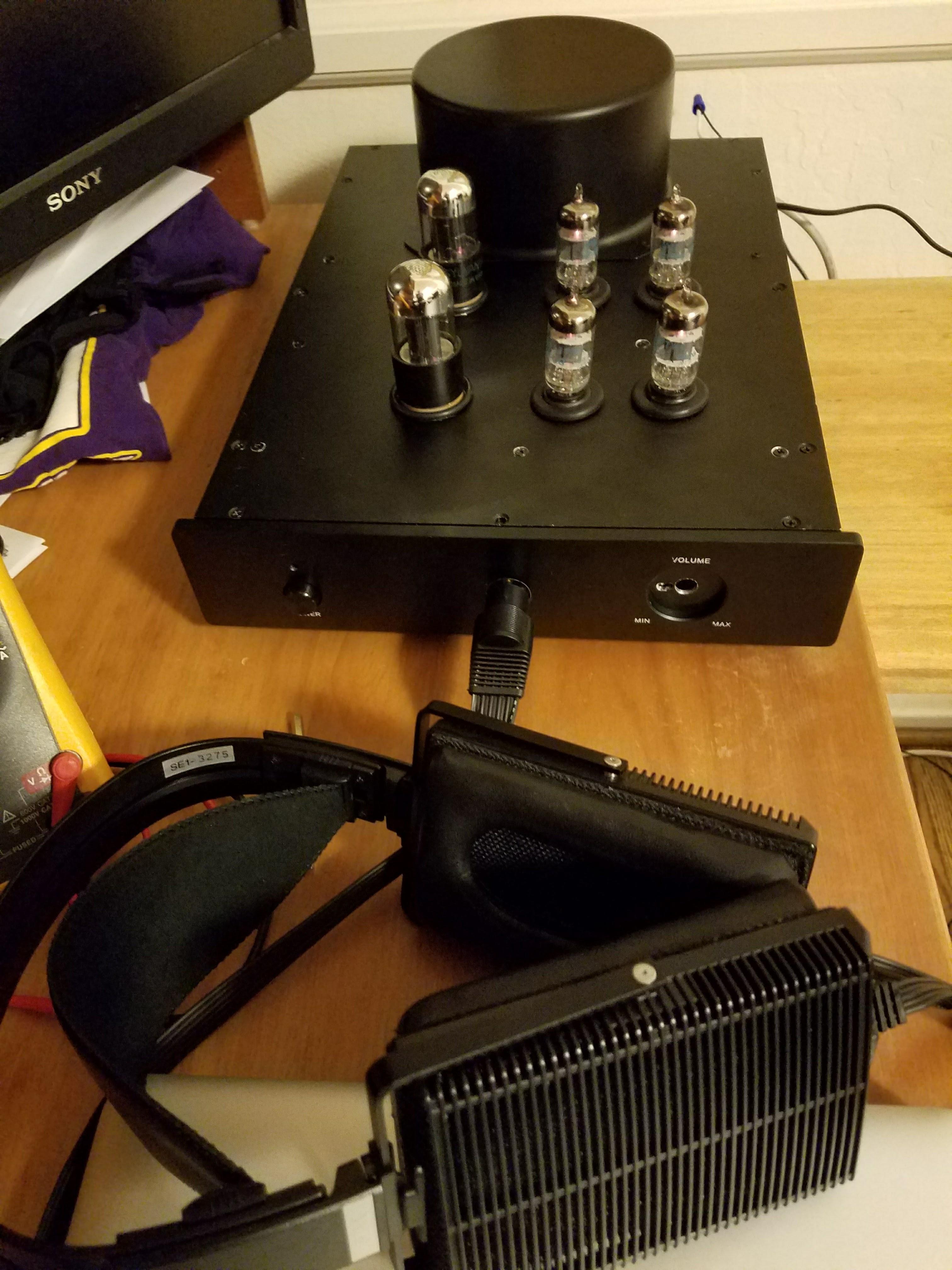
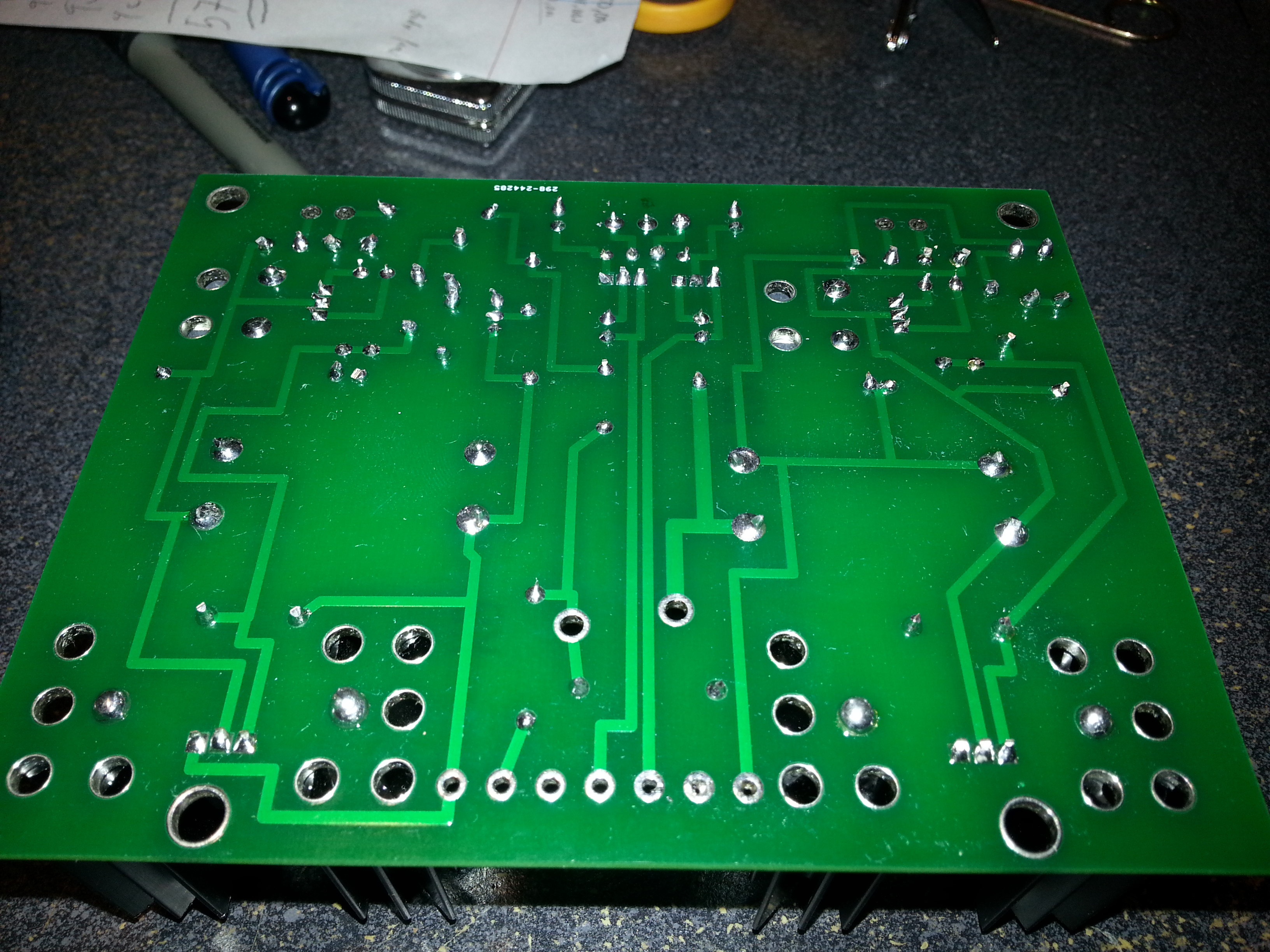
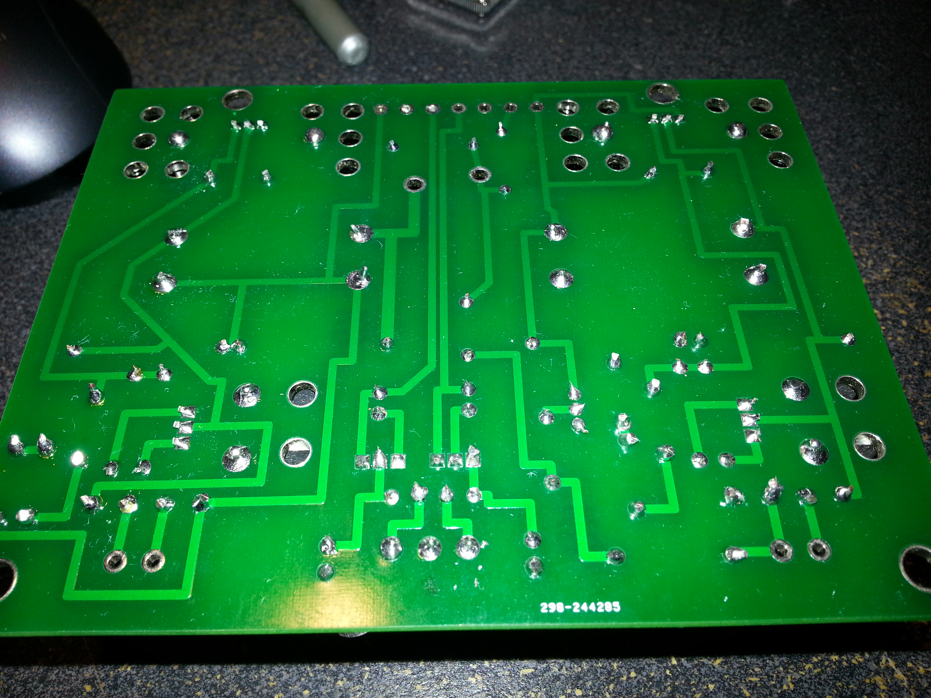
Thanks again Jose. Finally got it all into my case and did the grounding per your recommendation. Much better. Only slight hum I get appears to come from one of my 6SN7GTA's because the hum is only from 1 channel, and it switches channels when I switch the 6SN7GTA's. Also, with the grounding and with the elevation of my filaments per JimL's post, I was able to do all the adjustments per the guide and get to the right levels. This amp sounds really nice. A few pictures below. I have not installed the volume control yet.

-
Great article!!!! That is very helpful. I wonder if I can buy a loop breaker pre-made? Thanks jose!!!
-
Thanks jose!! I have better tubes coming in next week and will try those. They are supposed to be very well balanced (the 2 triodes in each tube well matched to each other). What do you mean when you say "separated the AC lines" and "ground loop breaker"? I am unfamiliar with those terms. And while on the topic of grounding, what is the strategy for grounding on this amp? I see the following grounding items: PSU ground AMP ground chassis ground earth ground (via 120vac plug) transformer shield wire POT (volume control) ground from inputs I was going to tie 1-5 all to a single ground point (star config) and leave POT ground floating since I cannot be sure all of my sources would use negative signal supply as ground. Does that make sense??
-
Thanks, Jim. I ended up elevating the filaments and that got rid of 99% of the hum. I put the output stage to B- (-370V). For the input stage, I made a voltage divider using 470K and 100K resistors across ground and B+, which gave me 65V for the input stage. Tweaking the 500K pots then removed what hum remained. I am using 300K plate resistors per the silkscreen. I will double check the tail current source and adjust as needed. I also did order a better set of balanced and matched tubes which hopefully will get rid of the last 1% of hum! I allowed myself about 3 hours of listening pleasure before I took it all apart and started the process of putting it all into a case. I am about 1/2 of the way there. I will post pictures when I get the system fully installed and running. Love my SRX-Plus!!!! BTW, I guess I win the award to longest time to complete a build! Started in November 2015 and finished in October 2017. But the sound was worth the wait!
-
Great summary, mwl168! Finally finished the build of my PSU (KGBH) and the SRX+ amp board. I dialed in the output current source, output current sink and input current sink using a pair of 9V batteries as described by JimL in response to your post. I checked the PSU and it is giving good and stable +/- 370V. Dialed in the bias voltage to 580v. Using 7918 on the KGBH to supply -18V for the amp's -20v connection. My transformer provides 2x 6.3V for the filaments (I modified the board to allow the 12AT7's to run on 6.3V to avoid getting another transformer; and yes, each set of tubes has its own 6.3 volts winding!). I just finished turning it on and letting it settle for about 15 minutes. Everything seems fine, but I am not able to zero out the plate voltages in step 6. Started off a 24V off with pot centered, and was only able to get it to about 10V off with pots all the way to their end. Also, I was not able to get the plate voltages down to 185V (my PSU is putting out 370V). No matter what I did to the 500 ohm pot, the plate voltage barely moved at all when adjusting the pot, and stayed at about 240V. Any idea what I am doing wrong? I am using a KGBH PSU and using the -18V from that PSU for the -20V input. Is perhaps my 370 B rail voltage too high for this amp?? I guess I can swap diodes and reduce the voltage to see if that helps. I am also getting a very loud 60hz hum. VERY loud. It is mostly attenuated when I return the 5k trim pots back to near center. Perhaps I have badly balanced tubes, causing the inability to zero out the plate voltage and causing hum when I try to turn the pots to extreme end of their range?? I carefully twisted the filament winding wires and they are nowhere near the inputs. Moving wires around does not attenuate the hum. But even with the hum, I did listen to the amp for about 10 minutes. I LOVE the sound!!! Much richer and full bodied than the SRD-7 I am currently using in conjunction with my traditional amp. Just the soft passages are ruined by that darned hum! Edit on hum issue: for those who might be looking at how I solved the hum: Used voltage divider to elevation the filament voltages. +65V for 12AT7s and -315V (or in my case, I just tied it to B- so -370V) for the 6SN7s I switched to different set of tubes. The ones I started with just hummed. After switching, much less hum More careful grounding of components Finally, to get rid of slight hum when volume control was at 11:00 to 5:00 position, I switched from a 50K pot to a 10K pot, which totally eliminated any hum when the volume control was in the mid/high region. Doing these 4 things, the amp is now virtually silent.
-
Yes, based on some friendly advice here, I now have a DY294 tester. What a great piece of equipment (though lacking in instructions for a newbie like me). I just threw the non-mouser parts into the trash, so never bothered to test those. But I am now doing 100% testing for diodes, caps, etc. It is nice to be able to match zeners so that both sides of my PSU are well matched.
-
Well, after almost 2 years off, I am back into building this project. I was able to build a stable KGBH PSU (actually 2 of them) with -20VDC added for the SRX-Plus. We are about 1/2 thru building the amp boards (1 for me, 1 for my son). Looking forward to reporting back as we make progress.
-
Well, they say time heals all wounds. Perhaps so, because after letting this project stay idle for almost 2 years, my son and I returned to the project last weekend and were able to build a very nice and stable PSU with the help of gepardCV who graciously provided an extra KGBH PSU board to me. I believe the issue with my original PSU was that I used non-mouser parts I got on eBay. When I purchased 100% mouser parts, it worked like a dream. Well, and maybe my son's soldering skills are more advanced than mine. But I did go back and unsoldered all the parts from the bad PSU and replaced with Mouser parts all by myself, and it too now works. So I learned the hard way to only use Mouser parts and avoid eBay like the devil. And to use younger hands to do some of the delicate soldering work. Now on to building a pair of SRX-Plus boards.
-
The boards really look great! I am sad that I will be traveling for the next 3 weeks and will not have a chance to start the build. mwl168, let me know what additional costs you incurred that I can help defray. You did everyone a great service in driving this group buy, so the least we can do is make sure you come out completely whole in terms of costs.
-
Boy, I really have to give credit to the amazing community of people here. I have received several PMs giving me great ideas and encouragement to continue with my learning in HV PCB work. People's generosity in time and information is humbling. I think I will try starting from scratch with a new batch of parts 100% from Mouser for the positive rail, and see if I can make this work. If nothing else, this is great practice for my upcoming SRX-Plus build. Thanks again everyone for the kindness and support.
-
Well, I turned it on this morning to prepare to take some more readings, and it blew up once again. Every diode on the positive rail gone to short condition (including the 24V one), with the 150V zener totally evaporated. Just like the past 2 times it happened. I had replaced all parts except for the 2 caps and the rectifier, and put in nylon screws on all heat sinks. The rectifier on the positive rail does continue to put out the expected 425VDC and appears very stable. And the bias does put out 580V rock stable. I give up! Why would a PSU work OK one day, then blow up the next? I never even moved it. Only issue was that the Positive rail was showing less volts (+310VDC) vs the negative rails which was producing the expected -345VDC. Ugh.
-
Maybe I am not reading voltages across the zeners correctly then. For example, on both rails (one that works, one that is 10% low), the voltage reading across the 'bottom' zener is about 0.9VDC on BOTH rails! I was expecting 100V since they are both 100V zeners. This is what seemed 'not right' to me. But I am new to this. What voltage should I be looking for across the 430K resistor and what does that indicate? Home voltage here in SFO area is 122 to 125 range over the last year. I have a home energy monitoring system that tracks usage and records voltages over time. In the past year, it has not gone outside that range.
-
Well, progress. I connected the PSU with the completely rebuilt positive side to the 300V x2 transformer, and no smoke / no POP! Getting 345V on negative rail. But only getting 310V on positive rail. Able to trim bias to 580. PSU is very stable at those readings. My guess is that I have a bad zener in the positive rail? I have 2x100 and 1x150. They all test fine as far as infinite ohms in one direction and 300-400 ohms in the other. Any way to tell which is bad? I tried connecting a lead to one side of the ladder and testing at each step, but the results (on both rails) were not what I expected. Almost no voltage on first 2, then quite a bit on final one, and a higher amount (more than the sum) across all 3. Maybe I am doing it wrong? BTW, the 1 amp fuses used on the secondary windings held just fine in testing. But the 1 amp and then 2 amp fuses on used on primary (110V going to the transformer) both blew pretty quickly (when I was plugging the transformer in after several times). A 5 amp on the primary is working great.
-
320V on both sides. +/- 2-3 volts over time. Boy, the more I think about it, I was stupid for not putting a fuse on this in the first place. Might have saved a lot of de-soldering/re-soldering and throwing away 6 zeners and 2 other devices. Dumb. Dumb. Dumb.
-
Well, I just ran a test with a 24VAC transformer. On the negative rail that was good, it reads -34VDC and holds it pretty steady. When I connect the 24VAC to the positive rail, I get 26V or so, and it slows drops as I measure it. If I remove the test leads and wait a few seconds, I will return to 26V or so but then slowly drop again. I tested the Bias output at the test point, and it gave 46V, and again dropped slowly as I kept the test leads connected. Is that normal? I was guessing that since the positive side is also driving the Bias current, it might behave differently at very low voltages. I like johnmclean's idea of putting fuses on the secondaries. Duh, should have done that in the first place. Any idea how low amperage of a fuse I can get by with for no load on this PSU? Maybe 1 amp fuse on the positive, and only test the positive side for now? Oh, and any harm in powering up one side and not the other?? I assume not, but wanted to double check. EDIT: I switched to using a cheap, but apparently high impedance, DVMM that showed higher readings and did not 'draw' so much current causing the reading to drop. Positive side now holds at about 30V, and negative side at about 35V, about same as before when on 24VAC transformer. Then, I took another step forward. I drove my 300V x2 toroidal transformer by a 24VAC transformer. Hooked it up to both side of the PSU. The 'good' negative side now shows 95VDC and holds steady. The positive side showed about 60VDC. Bias test point was about 120VDC. This has me a bit concerned that the positive side is so much lower, but it could be because of the additional power drain needed to run the bias, maybe?? EDIT 2: Well, I found out why the positive side was 'dropping'. I has my PCB sitting on a stack of paper. I did not think paper would be a problem. It was. It turns out the 8N80C was touching the paper and for some reason stoppled providing current to that rail. I put some plastic studs on the board to keep it away from anything, and it is now rock solid. Same voltage being held on both rails. At least, so far....
-
Hmmm. No variac, but would there be any benefit for me to hook up 110VAC to just the positive side, rather than 300VAC from the transformer? If nothing else, maybe less of an bang and less-vaporized zeners? If the circuit is working OK, it would put out some DC voltage still I assume, like maybe 150VDC? (1.4x110VAC)? Or, I have a 24VAC transformer as well I could try with.
-
Yes. Though I did have 2 from a friend who had extras. Not sure his source, and not sure which ones I put in! I ran resistance measurements across everything and the positive side seems to match the negative pretty accurately. No shorts, no cold joints, nothing appears amiss. I did NOT change the 10m90, though. I will do that now as well. I have put nylon screws in all the sinks as a precaution as well. Even after I replace the 10m90, I am really nervous about powering this thing up again!!!
-
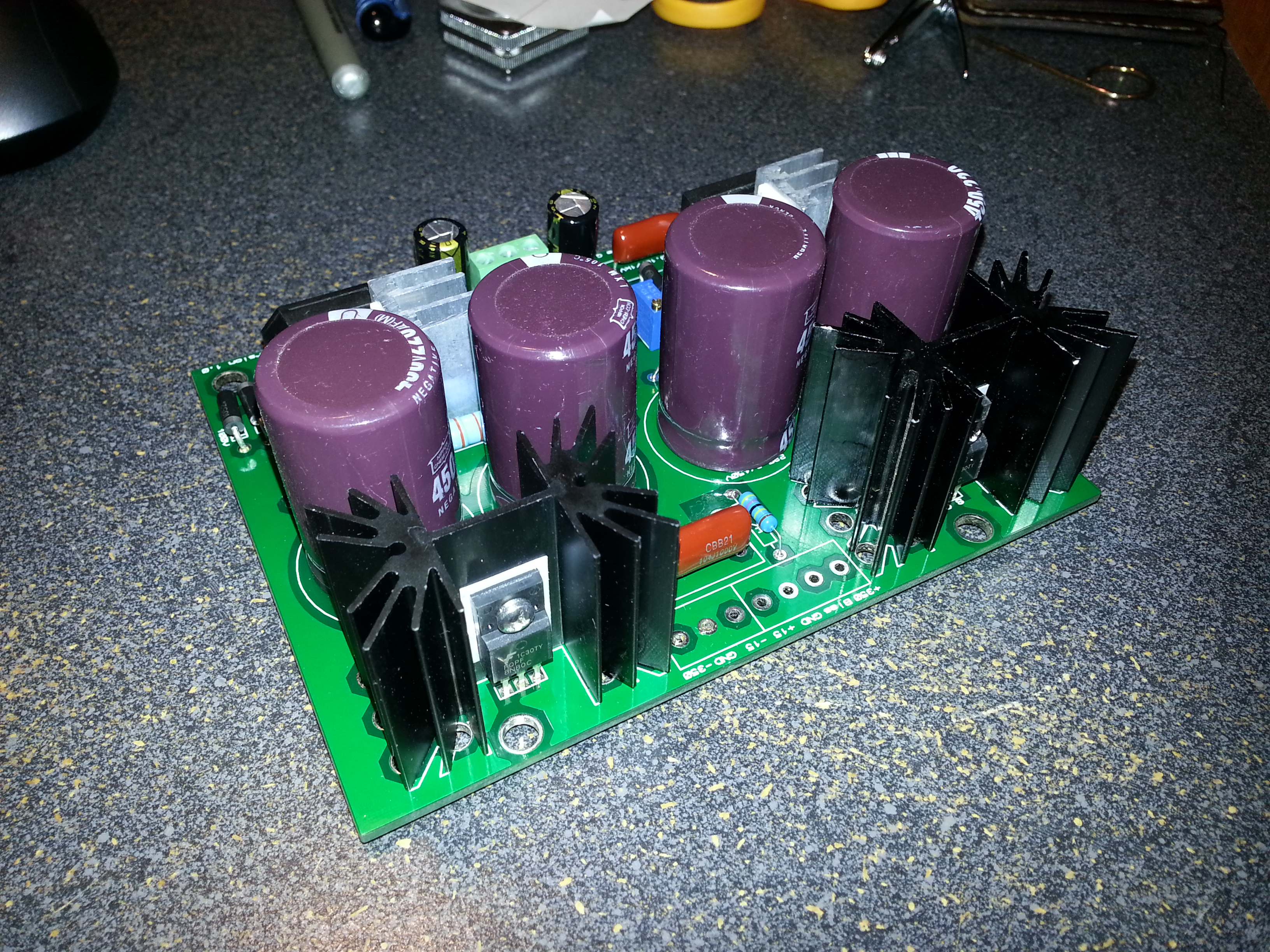
I will do that. I checked carefully, and used the correct sleeved insulator so that no contact was possible and the sleeve should have prevented arcing. But I will do this next. Just afraid this will not be enough! Used Aavid kit, Aavid 4880SG. seemed to be the right sleeve. Picture was before I added the connectors. Last picture I had before the big bang.
-
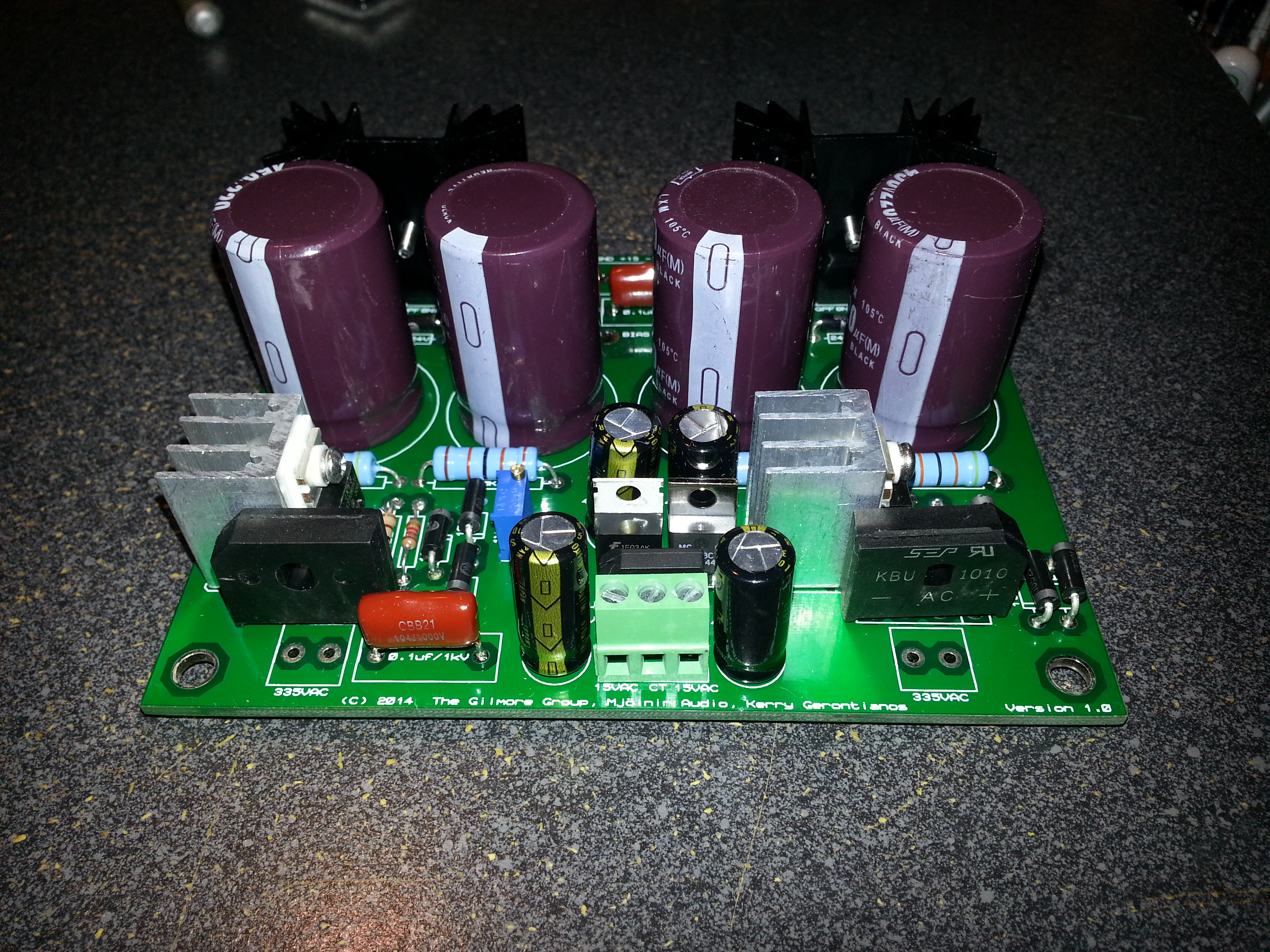
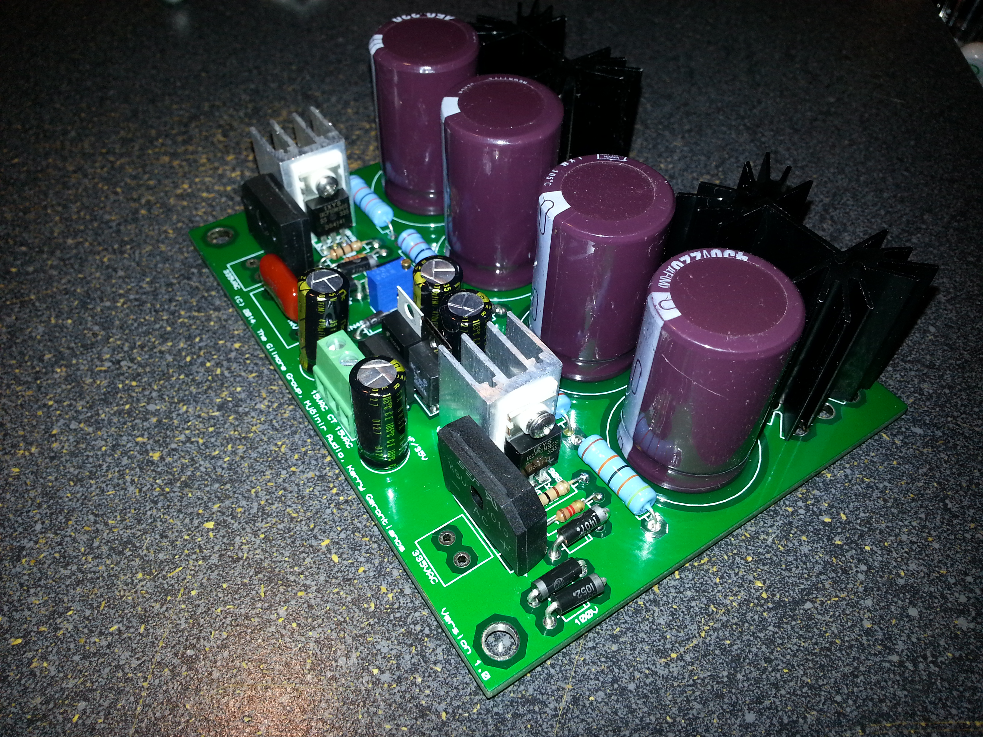
As somewhat of a learning experience, I decided to build a PSU using the kgbhultraminipsV4 board (KGBH). All seemed to go well in assembly, and I tested every adjacent solder point for proper continuity, and ensured no cold solder joints. Used proper heat sinks on the silicon devices wires while soldering to avoid overheating them. Cleaned the board with 99.99 alcohol. I set the board up with 2x100v and 1xs150V zeners to output 350V. I plugged it into a 300V x2 transformer (smartly using a very long extension cord in the garage) it I got a HUGE pop. I was using 5W zeners, and when they go, they really go! It was the Positive side of the PSU. One zener totally evaporated (100V), and all the others (100V, 150V and even the 24V) all went to shorted condition upon testing them. I replaced them all, along with the 8N80C for good measure. Rechecked everything even more carefully. No shorts, no cold joints, all zeners in proper direction. This time, it lasted about 2 seconds and made an even larger POP than last time. Loud enough for my wife to hear inside the house. I decided to test it while still plugged in, and found the negative side was fine. Outputting a very nice -345V. On the positive side, the bias was fine, and I was able to tune it to +580 with good stability. But the positive rail was outputting +420V. So pretty much what the rectifier should be doing without the zeners. I am somewhat at a loss at this point. I have included pictures I took before the first burn up. Do you see anything wrong enough to cause the zeners to commit suicide? I must be missing something pretty obvious for this big of a problem?
-
SUCCESS!!! It was pointed out to me (thanks sorenb!!) that the voltage measurements cannot be done from a typical digital voltage meter due to the impedance of the voltage meter itself. So I just installed my circuit into the non-pro SRD-7, hooked it up to my Integra ADM-20.4 power amp, and it sounds WONDERFUL!! This was the first time I was able to listen to my new SR-507s, and I am completely blown away. The bass is perfect. Incredibly powerful but very clean. I am hearing things I have never heard before in music I have listened to for years. I really am stunned by the quality. Thanks mwl168, spritzer, sorenb, JimL and Dr. Gilmore for the advice and direction on this successful upgrade. Now on to building my SRX-Plus amp to see how that compares. Not sure how much better the sound quality can get, but I can't wait to see.
-
Well, I built the circuit, but something is amiss. Measuring between the CT of the transformer (end of R105) and before the final 4m7 resistor (just after D106/C106) I am getting only 400V. Starting from the beginning of diode ladder, I get 80, 175, 250, 320, 365,400. Another person (RDK845) reported the same result when he built the circuit, in the "DIY transformer box thread" on another site. I am using a Fluke 77 IV to measure. Also, I tested the voltage between each diode, and it was between 94-97VDC across each diode, as expected. When I added up the 6 readings, I get ~580V, again as expected. But then when I measure from start of D101 to end of D106, I get only 420V. Really weird. Shouldn't DC volts add? Unfortunately, the other person who reported this never replied back with a solution. spritzer, I noticed you were involved in the other thread on the other site. Any insights into why I am getting these low reading??
-
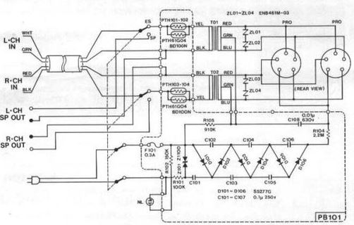
Finally getting around to changing my SRD-7 to Pro bias. I noticed the part surge suppressors (ZL01-ZL04) are not in the original non-pro version. I assume these are only there for accidental overload of the transformer, to protect it and the earspeakers? If so, I will just take the risk and be careful not to have the volume too high. Not sure where to find a similar part in any case. Here is the pro version schematic with the ZL01-04's: