-
Posts
13,700 -
Joined
-
Last visited
-
Days Won
38
Content Type
Profiles
Forums
Events
Everything posted by luvdunhill
-
I'd be more worried getting a prank call from a hacker if I had a pacemaker....
-

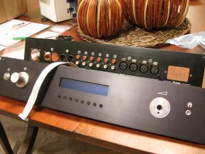
Working on a new panel... what do you think?
luvdunhill replied to luvdunhill's topic in Do It Yourself
hey, have you ever considered trying a First Watt F3 with your Gallos? I know you may be headed down another path, but I think it would be worth trying... Here's a F3+Gallo review.. 6moons audio reviews: FirstWatt F3/Gallo Ref 3.1 - A brief riff on good sound and the power required to make it -

Working on a new panel... what do you think?
luvdunhill replied to luvdunhill's topic in Do It Yourself
very cool. Though the next panels you'll see on a project of mine will be wood Material is headed down to Dr. Wood himself, from a purveyor of fine instrument woods in the northwest. Just have to keep him from "spilling" that pink dye all over the material.... -

Working on a new panel... what do you think?
luvdunhill replied to luvdunhill's topic in Do It Yourself
Akido? probably "Audio" honestly... -

Working on a new panel... what do you think?
luvdunhill replied to luvdunhill's topic in Do It Yourself
hmmm... ends with an "O".... let's see.... -

Ayre K-XR Pre and M-XR Monoblocks -- Who's heard them?
luvdunhill replied to Voltron's topic in Speakers
I will between his bouts with his spinal cord injury and his experimental Hyperbaric Oxygen Therapy (HBOT). -

Working on a new panel... what do you think?
luvdunhill replied to luvdunhill's topic in Do It Yourself
getting closer. Just need to decide what type of screws to use on the rear panel.. need to figure out how to mill the buttons now, as you can see the actuators in the picture. I went with a slight countersink on the rear as discussed above, so I need some "top hat" shaped buttons.. Also, I'm looking for a "smooth" Alps rotary decoder for the volume. -

NKOTB - TTVJ/Millett 307A Headphone Amp
luvdunhill replied to n_maher's topic in Headphone Amplification
Are you not worried about balanced to single-ended conversion issues, such as phase problems? -
So, I have never really found a good quick connect that I like... I used to buy some insulated parts and stick them on the end of an old power inlet that uses quick connects and try and pull the plastic part away quick enough to separate the metal from the plastic, then feed the wire through and solder then reattach the plastic and heat shrink the thing... that's not working with the last few ones I've tried. So, any recommendations? I'd really prefer solder types to crimp and they must be insulated. Thanks guys!
-

More control over Mac volume
luvdunhill replied to The Monkey's topic in GoRedwings19's Computer Help Hotline
Security research on a Mac simply sucks. Finding bugs on Macs is like a walk in the park. Believe it or not, it's harder to find reliable bugs on Windows platforms these days. Nobody cares about attacking Macs, target audience is just too small. I was controlling a 100,000 member bot net just last week.. I don't even know if that many Macs exist. -
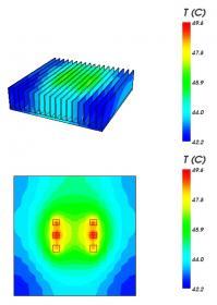
So, I'm working on a pair of monoblocks. swt61 has seen these monster heat sinks. 12.2" wide x 12" tall with 2.925" fins and 0.326" base, weight is 13 pounds... and I got four. I've done some thermal plots of 6 devices per heatsink on a small PCB. Each device is dissipating 14.8W x 6 devices x 4 channels ~ 350W. I'm wondering how much further I can push the devices. The sim data is very close to actual temperatures and since I don't want to drill holes under the devices for thermal probes, the simulator will be gospel. I don't really want to move the devices apart anymore, as I have a PCB in mind I'd like to accommodate, plus a design of my own. Datasheets for devices: http://www.fairchildsemi.com/ds/FQ%2FFQA12P20.pdf http://www.fairchildsemi.com/ds/FQ%2FFQA19N20C.pdf Attached are some plots and below is the tabular sim data: Thermal Design Details Heatsink type: Extrusion Part number: Extrusion: 9012 Weight: 5.26685 kg Heatsink dimensions: 309.96 mm wide x 304.8 mm long x 74.3 mm high Material: Aluminum Finish: B Environment Ambient Temperature: 25.0 C Altitude: 0.0 m Thermal Design Details Temperature Source Names %sc Power Tsink-avg Tsink-max Tcase Tjunction C C C C N2 0.3% 14.8 W 49.5 49.6 49.6 77.9 N1 0.3% 14.8 W 48.6 48.9 48.9 74.4 N3 0.3% 14.8 W 49.1 49.3 49.3 75.5 P2 0.3% 14.8 W 49.5 49.6 49.6 75.9 P1 0.3% 14.8 W 48.6 48.9 48.9 72.3 P3 0.3% 14.8 W 49.1 49.2 49.2 75.5
-
nope. I have 2 though. I also have 8 JISBOS buffers Just curious, do you know if any of the other TPA modules will be available tomorrow?
-
I' dunno, haven't surveyed solid state sources. Amb seems to think that "many" will not work fine. Here's amb's reply: "OK. 2.2K is quite low, users of the Joshua Tree should be mindful of source compatibility. A usual rule-of-thumb is that the input impedance of the amp (which is usually dominated by the volume pot/attenuator) should be at least 10x higher than the output impedance of the source. This means that the source should have an output Z of around 200 ohms or less. Many sources do not meet this criterion."
-
I'd also recommend doing a bit of math and considering if it will work given the input and output impedance requirements. amb commented about this over at HF in a thread somewhere.
-
I'm a bit bummed because I finally found a need for true rms measurement, and my B+K DMM doesn't do dat
-

Aristaeus came and went on HF.. lasted 20 minutes
luvdunhill replied to Luminette's topic in Headphone Amplification
justin: I've had good experiences with Turning Blanks | Pen Blanks | Available in AcryliWood and Dymondwood for stabilizing wood. Very reasonable too. -
MOTMOTMOTMOTMOTMOTMOTMOTMOTMOTMOTMOTMOTMOTMOTMOT
-

Aristaeus came and went on HF.. lasted 20 minutes
luvdunhill replied to Luminette's topic in Headphone Amplification
was this a public "uninvite"? -

Aristaeus came and went on HF.. lasted 20 minutes
luvdunhill replied to Luminette's topic in Headphone Amplification
... and? would you have been more impressed if it changed owners without an advertisement? -
after you, sir...
-
The Texas contingent would be very interested in listening to it
-
problem with the Blue Hawaii is you also need a heat resistant gauntlet
-
I'm going to go out on a limb here, but once you get the Blue Hawaii biased correctly, it shouldn't need much change from tube to tube. I biased pabbi1's Blue Hawaii by ensuring the amp was stable with the lid on (most people probably don't do this) and all four matched pairs were right on the money when inserted into the amp. YMMV and I'm sure others have biased this amp waaay more than I have, but that's at least my experience on 2 Blue Hawaiis. Also, I'd recommend getting an insulated trim pot adjuster, don't use a screwdriver.


