

luvdunhill
High Rollers
-
Joined
-
Last visited
Everything posted by luvdunhill
-
Then it is a DIN cable of sorts. Google is your friend.
-
There really isn't a standard for an I2S cable. But, one connector I've seen in use goes by the name 13W3 and used to be used on sold SGI and Sun workstations. Search Ebay and see what you can find. These also pop-up on Audiogon from time to time. I think Camelot made one. The other connector I've seen is the RJXX variety and should be easy to track down.
-
-
They both sound great! At the moment, I have an adjustable RIAA filter in the Pearl to select between Decca/Columbia/etc. curves and uses an all polystyrene RIAA filter. I'll be using this with an Ortofon SPU cartridge. Different cartridges, and different applications. I've tweaked both circuits to sound the way I want them to given their intended application. If you're really interested in a comparison, I'm not sure how to really provide that, since from the start I've approached these projects as separate and had a very specific intended use for both. I only hooked the Pearl up once to my LOMC cartridge just to verify the gain for you and give a quick listen, hardly time to form an opinion... I didn't really see the need to do so Congratulations on your purchase though!
-
well, that depends on how the XONO is configured. I cannot speak to the commercial version. Since it mine has a balanced output, the maximum gain is ~75dB and -6dB from this in SE mode. I have both a -10dB and -4dB gain reduction jumpers on my unit, so can can reduce the balanced gain down to 61dB. I've also customized the gain of the MM stage as well in a similar fashion. At this point, the gain is roughly the same as the Pearl, hence my judgment that the quoted spec of 60dB is pretty close, if not dead on. With my 0.24mV Bloom, I listen with the balanced outputs and the -4dB switch enabled, as this is just the right amount of gain for me (currently).
-
wow, that's similar to the old Airy3 I had. Get ready to start questioning your tonearm Did you get the SB/GB weight? You might have issues, as these cartridges are so light.. Same with mating the compliance of the cart with the effective mass of the tonearm.
-
recase it into something like this: There's a guy on ebay that sells them for a good price ... cannot find the link for some reason now though
-
can you measure output voltage at the speakers when playing at what you'd consider a reasonable volume? You could calculate the gain required to get that voltage from 0.24mV. Remember, with 60dB gain and 0.24mV source you have .240 V at the input to your preamp. My guess is you need more gain.
-
um, use a balance pot?
-
looks interesting: diyAudio Forums - ESL Justrealmusic DIY Speakers for sale - Page 1
-
tough call.. I'd start with the Bloom 0.48mV and see if the sound is for you. Any ideas what is inside this little gem:
-
so, the little material on this panel to accept threads has become somewhat of a fail, like most of my casing endeavors. So, I was thinking... why not just bond the standoffs permanently to the face plate (there are still threads, so alignment isn't a huge issue)? So, hence my question... Anything particular, such as Lock-Tite/JB Weld/etc. that would work well in this case (blind holes, Aluminum to aluminum, yes lame pun intended)
-
how do you think a single omni would do for a mono rig?
-
yup, RAAL units are very close: RAAL 140-15D
-
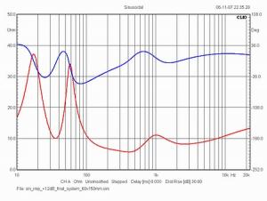
here's the final impedance of the 2-way I'm using the Raidho unit in
-
I'd recommend getting them to him in a hurry! (so we can hear them at the upcoming DFW meet)
-
well, remember those measurements are on an open baffle..
-
very good question I'd be worried about the bass response. Also, I researched these RAAL ribbons quite a bit, and heard a couple projects with them. They are very nice sounding, but personally I preferred the Raidho units. I think the RAAL ribbons are really meant to be driven by tube gear (see their marketing stuff, they were almost designed this way) and that wasn't a limitation I was willing to accept at this price range...
-
you can definitely order them separately. Here's one link: RAAL 140-15D Ribbon Tweeter (with optional Amorphous Core) from Madisound and http://www.madisound.com/catalog/product_info.php?manufacturers_id=178&products_id=8323
-
They look to me like the standard RAAL ribbon offerings, so yes they're available... I could be wrong though ...
-
wow, finally a new headphone to get excited about
-
perhaps there is a size limit?
-
mighty respectable of you. we're on the same page then
-
wait, none of those are options on the order page?!
-
I'm not sure how this would be given the schematic and the M-M-M-MASSIVE upgrade from Wima to Auricaps ... but hey, whatever floats your boat / empties your wallet.

