-
Posts
13,715 -
Joined
-
Last visited
-
Days Won
39
Content Type
Profiles
Forums
Events
Everything posted by luvdunhill
-
nice! what percentage have been banned from CanJam?
-

LDR (Light Dependent Resistor) Volume Control
luvdunhill replied to Tachikoma's topic in Audio Accessories
no offense to George, but the one Choky is selling should sound a lot better. I'd recommend trying that out one.. includes a nice integrated buffer to boot: diyAudio Forums - Poor Serbian Man Lightspeed packages - Page 1 -
I'm a huge fan of slot ports... but, I think that is probably the sloppiest part of the build.. not that I could do better, but.... I'm wondering if the exit looks like that, then what the internal part of the port looks like (is it rounded over, etc.)... edit, it may not even be a proper slot port, just an opening.. in which case, that's kinda fail in my book.
-
Actually, the main difference here is the width. Those R-Theta are only 7" wide. The ones Steve and I have are a full 12" wide.
-
sure, if you're willing to by a ton of extrusion. They are made by R-Theta.
-
looks good Steve! A few notes: measure the resistance between the binding posts and the chassis. This should be an open circuit, or infinite resistance. Measure the same between the RCA and chassis. These should have come with shoulder washers to make sure the post won't contact the hole... now's a good time to verify this. Those black discs (thermistors) in the PSU will get warm. I'd recommend heat shrinking the leads and trimming them down so they don't accidentally get knocked around. Important thing is that nothing touches the leads and the don't really touch anything and are relatively secure so they won't move around. For example, you could bend the one on the rear panel at a 90 degree angle to get it away from the aluminum case. Same thing with the little thermistors on the amp boards. Also, you'll want to sort of bend the leads of these devices down so the black head is sort of near the mosfets. Think of these like little thermometer probes that need to sense the temperature of the mosfets. The rest of the wiring is sorta simple. You need to run wires from the +V on each boards to the caps (upper left I think?) and -V on each board to the other output (lower right?) and GND to the copper. Also, you need to connect the inputs and outputs to the rear panels. I'll leave this as an exercise to the reader Leave lots of slack in the wiring to facilitate tearing things down if need be. Fantastic work in so little time!
-
yup, this isn't really an issue at all. Take for example the following topologies: active crossovers, PLLXO crossovers, digital domain crossovers (Behringer devices, etc.). All of these have the potentially long cable in the same location in the circuit with no detriment. From my experience, there are no negatives. The positives that I've personally measured are: less inductive coupling due to more room to properly layout inductors. If you're building a large floorstander, this is less of an issue, as you have more room. But if you have a small three-way with 30 odd components per channel, there is no way you can cram it in a speaker enclosure without detriment in this area. Even more to the point, is I have a small three way with four inductors per channel. There is no way that you can space these out properly. This is pretty easy to measure and verify. This also includes interaction with the drivers own inductance, as you pointed out. less microphonics from the capacitors. Well, I guess this may be harder to convince people of, but it's really noticeable when your in the trenches designing a crossover. The best way to mitigate this if you want to stick the crossover in the enclosure is the use of box caps, as I've found they are far less susceptible.... yes, you'll need a lot of them in some cases, but they are well worth it. Some people damp the hell out of the axial capacitors with silicon, but this just doesn't work so well I've found. Anyways, have fun!
-
yeah, I'd go with the 40 step TKD for approximately the same price. Also, +-2dB accuracy to log curve and +-1dB channel matching seems rather lame to me...
-
You're building someone else's design on the one hand, and on the other hand making blind judgments on what is a good idea and what's not? There are a lot of good reasons to do external crossovers... the added resistance of the wire is pretty much trivial, but if this concerns you, it's easy enough to compensate for it.
-
how much? Aren't they only ~20% cheaper than a RK50? 10K is fine for anything I'd be using it for ...
-
actually, that is very very sweet. I hope to try one!
-
Smeggy: I dropped the parts in the mail this morning!
-
Jacob: Nice! I would prefer something other than constant slope, as I have rather low output sources... Looks like I could change the calculation of stageAttenuations to be a piecewise function to do this?
-
yeah, even scarier is that big lump of the second hardest wood known to man in his workshop. .... I'm not even going there, it's too easy.
-
I'd say your post was about a three-thirds ass decent reply.
-
oh I wasn't implying that they'd do it right or that it was a good choice...don't get me wrong.. just curious why they didn't attempt to do it then screw it up ...
-
heh. If you look at the front and back of your transistors, you'll see that everything is rather isolated.. i.e. no metal on the top or inside the hole. If you look at the transistors on the Millet, you'll see there is a metal tab. If you look at the datasheet for those transistors, you'll see the tab is tied to one of the three pins and ultimately to the circuit. They is why they need to be isolated.
-
I kinda wonder why Mikhail or Ray didn't try to rig up something using a concertina/cathodyne to feed the balanced frenzy..
-
I dunno, budding DIYer, do you?
-
I got those phenolic shoulder washers too... Looking for the envelope now with your return address. How many do you need? I have lock washers and socket head screws as well... anything else you need?
-
I'd like to get a recommended BOM together before we order the boards. Just so we can verify that all the spacings are appropriately sized for components we actually want to use.
-
Generically, they are called heat sink pads. They come in all shapes and sizes. Most likely you want electrically isolated pads. Here's the catalog page at Digikey that is most appropriate: http://dkc3.digikey.com/PDF/T091/P1177.pdf Aavid Thermalloy also makes some that are sold at Mouser. If you need onesy-twosys, PM me your address and I'll drop them in the mail BTW, the 6-pin socket arrived and my template is slated to arrive today... so once I get home, we'll see how it fits!
-
ah, a subject that's deeply been suppressed it seems. Rather than messing with complex math, I just calculated the magnitude 1/(SQRT(1+(wRC)^2))... more to follow!
-
meh, I figured all the above out, plus how to move the non-linearity to the last 2 loudest steps.. even then, my max deviation is 0.50% That VB function didn't work for me, but writing an appropriate one was rather simple it turns out. Okay, so next order business is a Bode plot for frequency response. Of course, Excel seems to be a fail on that out of the box. So... rolling up the sleeves..
-
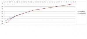
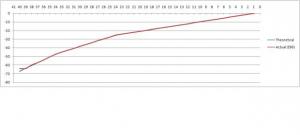
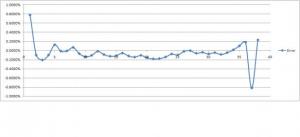
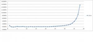
Cool! I'll try it out! The below results are using the VLOOKUP function. So, this turns out to give some unexpected results. The basic schematic is a series attenuator like this: Notice I'm using a three slope curve, not the traditional log curve. The issue is once you get to the higher attenuation steps, things go crazy. I'm still trying to figure out why. At first, I figured it was because there are course E96 values < 10 ohm in film resistor line I'm looking at. But, then I just set the values < 10 to the exact theoretical value, and Exhibit A (atten1.jpg) is the resulting graph. Notice the deviation. My other theory is somehow the error from the series resistors above somehow catches up and throws the balance off... anyways, any ideas? So, next I plotted the error between the theoretical value and the E96 values on another graph, see Exhibit B (atten2.jpg) and the non linearity at both ends of the stepper becomes obvious. Now, if you sit and play with the lower values, you can actually coerce the values a bit, but then you get this strange deal with the first 2 steps, where you have a NOOP of sort and the volume doesn't change. This is rather strange, but maybe acceptable. See atten3.jpg and atten4.jpg. Still working on some other features, then I can post the spreadsheet. A few questions in addition to comments on the above: What's the best way to provide a "mute" stop (yeah, stupid question I know)? Is there any reason I cannot use the current sensing thin film resistors for values < 10 ohm, or alternately, how hard is it to mount smaller SMD resistors on 0805 pads, if perhaps they are available < 10 ohm in smaller case sizes?


