-
Posts
13,677 -
Joined
-
Last visited
-
Days Won
35
Content Type
Profiles
Forums
Events
Everything posted by luvdunhill
-
maybe it has a greater effect on lower level pain signals ya know, it starts clipping at some point or buffers get overflown..
-
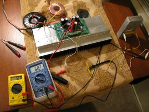
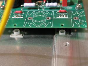
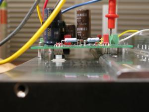
well, after tapping 8 holes at #6 instead of #4 , I had to order some parts from Mouser and they just arrived. Namely, the four #6 standoffs and the nylon clad steel screws. Since I cannot fit a shoulder washer anymore to isolate the MOSFETs, I decided to try some nylon. With these fancy screws I cannot get as much torque as using just plain nylon unfortunately, as the inside screw starts to spin a bit... So, I may go back to pure nylon... Anyways, sorta got lucky this worked out. Perhaps there are some other creative solutions, but I couldn't think of any that didn't require tapping and milling my heat sink and/or bracket. Meters show ~+-30V drawing 1.2A. Things get rather toasty Now to get the FETs mounted to the DynaFET boards and get this show on the road!
-
Think of it this way... That cartridge didn't cost you $5K, and it's doubtfully worth $5K on the used market... There, does that help?
-
Jacob: Would you consider adding a way to mount a small PCB in place of the input transformer? I'm thinking similar to what Nelson Pass does for the UGS boards in his preamps. He uses two banks of DIP pins to connect the daugherboard and you'd route up the necessary I/O signals up via these pins. I have a solid state SE to Balanced design I'd like to try down the road a bit, and it would be nice to just snap it into the boards.
-
I understand, I just don't have the equipment to convince myself one way or the other (and trust few people's word on the subject), so I figured as short as possible and definitely less than 6" will be what I shoot for.
-
6" is a rather standard recommendation for I2S. There is a line driver circuit by Elso Kwak around if you want to go longer, but IMHO it just invites many issues I don't want to deal with. Now as you said, whether this is relevant, I don't know, but seems like a sane place to start.
-
well, remember this will be digital, not analog connections (think I2S).
-
Definitely hardwire. I wouldn't run the lines more than 6 inches, without a line driver circuit. The real question is how much room is there in the case for a few power supplies and what not. Have you dug up all the threads that reference this from DiyA and HF? If so, I'd like a short list of them to read over.
-
at least the cable elevators are still there!
-
Tkam, do you like your TomTom 730? I'm considering either a GPS or upgrading my wife's Blackberry to an iPhone.... I'm considering the Garmin Nuvi 760 as well.
-

Another One Bites The Dust: SDS-DOA
luvdunhill replied to Voltron's topic in Headphone Amplification
I'd guess it would be as simple as replacing the pass element. The diagnosis makes sense to me. Hopefully, nothing in the amp section went along with it. -

Best Single Ended USB DAC under 1000?
luvdunhill replied to Jeepster's topic in Home Source Components
yup, in general, the ones with the separate clock board that isn't integrated into the main boards are the more desirable units. The issue is, these were the ones with the bad caps that must be replaced... so, you're right in that a minimal amount of upgrades need to be done to these. -
yup, I agree
-
Wallander (well, last night)
-

Another One Bites The Dust: SDS-DOA
luvdunhill replied to Voltron's topic in Headphone Amplification
Too bad I have the family with me, or this would be fun to look at and document, as I'll be in the area for the last two weeks in July. Anything in the area that I could sidetrack the family into doing without me? -

Another One Bites The Dust: SDS-DOA
luvdunhill replied to Voltron's topic in Headphone Amplification
Al: If I can do anything, just let me know. You're definitely in a hands of a very capable crowd around here! -
x2 what Nate said. If you cannot go wild on the ventilation (including a vented bottom, IMHO), consider running the power supply rails lower and/or a lower bias point, as that will help with the heat.
-

Shurter IEC filter module fusedrawer. Does anyone have one?
luvdunhill replied to MASantos's topic in Do It Yourself
just dropped it onto my Mouser order Let me know where I should send it! -

Shurter IEC filter module fusedrawer. Does anyone have one?
luvdunhill replied to MASantos's topic in Do It Yourself
Manuel: Let me see what I can do -
I was sorta curious what these will start to go for. What's your opinion?
-

Best Single Ended USB DAC under 1000?
luvdunhill replied to Jeepster's topic in Home Source Components
This is pretty common with most modded gear. The number of permutations isn't quite as many as Tony suggests, but there are 6 versions that I know of that really fall into two major categories. -
nope, a bit larger than Justin's and are custom milled so that rails won't be necessary, as they are integrated into the heat sinks themselves. They are the largest profile Conrad makes. yeah, I'm hoping the phase change compound will make them easier to separate, but more on that later, as I'm still playing with it
-
oh ok. The cloth was clean as a whistle with water and a plain dry cloth. It wasn't until I added the oil that the black started come off.. and it was pitch black. Do you think there is a fixed amount of tiny particles on the heat sink, or it would keep rubbing off black as long as I tried to rub down the heat sink with oil?
-
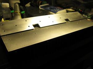
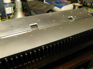
Heat sinks and brackets are ready after using 600 grit sand paper, if I apply a bit of oil and rub the surfaces I end up with a black rag (um... okay, anyways) I'm not sure why this is, or what would be black, besides perhaps the sandpaper? Who knows.... Then, I mated them together with oil and couldn't get them apart... wish I had a vise or something... I ended up putting a small gouge in the heat sink when I finally got them apart by putting a lot of force on the assembly by using the angle as a cantilever of sorts... Looked through all my power resistors can don't have anything low enough (HV junkie), without paralleling 50 or so resistors together... so I'll have to head up to Frys, as I sorta want to test the sigma22 at load before doing much else. Hopefully this number of holes to secure the bracket to the heat sink will put me as the secure leader in team overkill, with digger945 in second place with plans of a measly "2 maybe 3 #6 screws"
-
are they like under your bed? you're going to have the most gear per square inch of living area I've ever seen!


