

luvdunhill
High Rollers
-
Joined
-
Last visited
Everything posted by luvdunhill
-
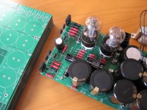
I dunno, it's hard to tell if there is a solder mask when FR4 isn't used, which seems likely here. I'm assuming stencils were used for the SMT stuff, so I'm betting there is some sort of solder resist layer.
-
Well, I finished up testing the 8 FET version and mailed off the board to digger945. Once you get it Scott, can you do me one quick favor? Measure the values of the two "500 ohm" pots.. I think I'm going to try on my final build using a 470R resistor for one and a 510R resistor for the other, but want to verify which is higher value, as it's not clear from my notes. I think I'd like to remove the trim pots, and let the servo can keep things in check, per the original schematic. The final recommendation for the bias pot, is a 20K pot with 3K3 in series, as well as halving the two 20K resistors. In the final version, I used 1 ohm ballast resistors and they worked great. Truth be told, I would have liked to try 0.47R, but I think 1 ohm is good. I know the original target was 125mA per device. I think this is a good number, but felt like I preferred even more current, as the old addage that MOSFETs love current seems to be true. With the 8 FET configuration, the lowest bias you can really get, without further modifications (i.e. trial and error) to the circuit was 165mA per FET, given the values I used. If you don't have the heat sink to handle this, I'd recommend sticking with four FETs. Most people should plan on the four FET version, in my opinion. I maximum bias tried in the 8 FET configuration was 315mA per FET, for a total draw on the negative rail (where my ammeter was) of 1.3A. Things were rock stable, and in fact I didn't have the servo opamp installed. This thing does indeed scale quite nicely. I cannot wait to try it with speakers Anyways, good stuff. Let's start working on the modifications to the boards and get these off to production as soon as possible. I'll work on drawing up a final BOM by Monday and we can start firming up those numbers and working the logistics. Sooner we get cracking on this stuff, the sooner everyone can start building
-
eh, try using one of these: OTTO 2:1 Switching Module rated only to 3A though, but might do the trick.
-
Is it possible that the free air impedance could be different from the impedance when loaded with the dummy head, or whatever Headroom uses? Did he measure them while they were on his head?
-
ask "opc" at DiyA, he has files that he will (usually) send out with decent documentation, albeit not fully sanctioned, IIRC.
-
I thought I saw a PPTC somewhere in there?
-
more likely the temperatures weren't calculated properly. Proper design should not assume any air flow (unless a fan is included, of course).
-
Dusty, can you post the two graphs in question, preferably including an impedance plot?
-
It probably runs more stable warm. There seems to be a fine line between too much ventilation, which can cause temperature gradients in the case, and not enough ventilation which can cause stability and longevity issues.
-
come on Dusty, you can do better than that.. that typo almost does the work for you!
-
Ditto on Fry's. Guess I need to find something online. So, lowered the output resistors to 1 ohm and everything was stable. With the Dynahi current level, the current was shared exactly the same. Just for reference, the variance is 2mV on one side and 5mV on the other. With the insane output current setting (400mA per FET) things tightened up from a 17mV spread on one side, to 4mV and 66mV (my worse-case scenario) to 30mV difference. I think this is just about the limit of how hard I can both push the FETs and my heat sinks. With the 8 FETs, my targets will be 75mA and 200mA, and perform all the same measurements at these points. I gathered the data for dissipation on all the buffer transistors, just need to do some math. They still seem warm to me. Ideally, it would be nice if we could make sure the "faces" of the BJTs point away from each other, as this just exacerbates the heat... I think it would be a worthwhile change, albeit not simple I'd guess.
-
[ame=http://www.amazon.com/Telemann-Twelve-Fantasias-Gulliver-Violins/dp/B0000007EP/ref=cm_cr_pr_product_top]Amazon.com: Telemann: Twelve Fantasias for Violin Solo; Gulliver Suite for Two Violins: Georg Philipp Telemann, Andrew Manze, Caroline Balding: Music[/ame] The Cleveland Quartet Beethoven Box Set, but particularly the "Razumovsky" Quartets: http://www.concordmusicgroup.com/albums/Beethoven-Quartet-In-B-flat-Major-Quartet-In-F-Maj/
-
Just had a probe slip and ended in a projectile BJT. That's a first. Just finished replacing the transistors and it's back up and running.
-
kinda broad question Could you narrow down things to solo, chamber, orchestra, opera, etc? Here's a token recommendation: [ame=http://www.amazon.com/J-S-Bach-Sonatas-Partitas-1001-1006/dp/B00097HE8U/ref=sr_1_3?ie=UTF8&s=music&qid=1246227869&sr=8-3]Amazon.com: J.S. Bach: Sonatas and Partitas for Solo Violin, BWV 1001-1006: Johann Sebastian Bach, Julia Fischer: Music[/ame]
-
that would be very wise
-
That would be really cool, could you suggest something simple? I don't mind sacrificing this board once I finish with it to this test I think it would be a worthwhile addition to the boards. I figured a shorting switch would work, but maybe not?
-
I can. I hesitate to describe the difference as it will be forever recorded in the annals of time and all further impressions will either mirror mine or be polar opposite I'll wait for someone else to take the plunge first.
-
Cool, all worked out. I'll get with digger945 and see if he can verify (and I'll answer your PM as well Then I'll recalculate the values with 8 output FETs once I get to that point, either way, this won't hold up the board production. Jacob, can we change that bias pot to a pot with series resistor? I think that's the last change to the board. Let's see what you have for changes, and get these boards ordered. Anyone ordering parts from Digikey, or can we tack another $7 onto the R&D budget?
-
Lead betternice line of work, switching out LEDs? I can recommend Fitz as an expert LED matcher, if you're ever in the market.while we have you here ... Seems there are different distortion spectra from the two FB points. Did you compare the two and have a preference? In other words, is the distortion from allowing the diamond buffer and output stage to run open loop "pleasing" in your opinion?Kevin: You need to also lower the 20K resistors it seems. I cut them in half and raised the pot to 50K. The result is a lot less touchy than raising the pot to 100K, and looks to be a winner.same as Dynahi, plus the current for the buffers, so 380mA. Could you measure your current draw more exactly for me? Voltage drop across one of the 20 ohm resistors would work.. or measure a few per board and average them.

Important Information
By using this site, you agree to our Terms of Use.