-
Posts
8,502 -
Joined
-
Last visited
-
Days Won
7
Content Type
Profiles
Forums
Events
Everything posted by Pars
-
Damn, a class act. RIP Mr. Belafonte.
-

and now for something completely different part 3
Pars replied to kevin gilmore's topic in Do It Yourself
From recall, it seemed that the Dynahi was more clinical than the CFA3. Not that the CFA3 lacks detail at all, I guess your description of rude might be a good way of putting it. They are both great amps, I just prefer the CFA. -

and now for something completely different part 3
Pars replied to kevin gilmore's topic in Do It Yourself
I personally prefer the CFP3 to a Dynahi, but I have only compared SE directly. The CFP3 is probably my favorite dynamic amp, but my SE Dynafet is awfully close (and better than an SE Dynahi in my opinion). I've never built a Beta22, but have heard them at meets (10 or more years ago). I don't recall being particularly impressed then, even though I have a lot of respect for Ti. -
Hence the !digitalRead call. Clever.
-
a
-
Happy belated Birthday!
-
Happy belated Birthday!
-
Tested the two C2M devices I pulled out of the Carbon board last night on one of those cheap chinese device testers. One of them tested as an NPN, the other as a MOS FET. Another new one tested as a MOS FET as well, so guessing the one that thought it was an NPN was the bad one. Tossed it.
-
There are ways of doing that. Can't remember the exact one I used, but put Catalina on my mid-2012 Mac Mini doing this, and it worked fine.
-
That is evoking shades of Lampizator or Ric Shultz soldering build qualities...
-
Happy Birthday Doug! I hope you have a great one (and weekend)!
-
Yellowjackets season 2. Has not disappointed so far though somewhat slow moving...
-
For RK50, you can look at Octopart here: https://octopart.com/rk50114a0001-alps-7850315. Otherwise, the TKD 4CP2500s are well thought of, and the 4CP601s aren't too far behind. Much cheaper. As for board placement, I would guess those that place the board at the rear do so to keep them close to the input jacks (noise). This would normally require that the volume pot use a shaft extender and also be placed at the back. For raising the resistors, 2mm should be plenty.
-
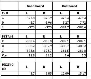
I rechecked all resistors and everything was correct, though I noticed that the 1M resistors ohmed out at ~750K or so on the bad board vs. around 500K on the good board. I went ahead and changed out the C2Ms. After that, the 1M resistors now ohmed out at ~500K in board. Fired it up, and the tabs of the DN2540s were now around 3-ish volts. Vce on the PZTA42s is now ~13+ volts, so SUCCESS!
-
I'll recheck those, could have swapped them. I didn't do any mods other than changing the 174K resistors for 150K, and that was done on both boards. I just redid the bad board the other night. EDIT: you were correct, those measurements were flipped. Rechecked and verified.
-
Took some more measurements, but still need to verify resistors (again): Also measured the DN2540 tab to ground, and noticed a difference in these which could account for the Vce difference? Coincidence? All voltages to ground.
-
Yeah, dem der tings. I'm really doubting I need any now, but might hit you up for a couple if I determine that is the problem. You're taunting me, right?
-
I remeasured the drains of the C2Ms to ground and they looked OK between the boards. I did a diode test of all the SMD transistors and the C2Ms between boards and they all matched (that took about an hour). I replaced the DN2540s to no avail. The offset went up a bit (18mA), but readjusted that to 17.5mA. I guess I'll replace the C2Ms next, and maybe go over the resistors once again. I'll also take a closer look at the PZTA42 voltages. I don't have any more of these, but could get some. I also don't have any 10M90s, and can't get any that I am aware of for quite some time.
-
No, I did not measure the Vce prior to making the mod.
-
OK, didn't do much on this this weekend, but did take another look today. Pulled the board off the heatsink and examined it. Other than a bit of heatsink compound, didn't really find anything. I resoldered a bit on the PZTA42s and a couple of other SMD PZTAs. Hooked it back up and no change. The bases on the PZTA42s looked the same between boards (-393Vdc). The one thing I noticed is the drains of the C2M devices on the good board were more or less the same at -3.93 V or so (to gnd), but on the bad board they varied from device (-1.9V to -5.xV on the other one). I think since I have them, I will change out the DN2540s since I'm not finding anything else. I was starting to think it might be a front end issue, but since the bases of the PZTA42s seemed the same between boards, I can probably rule that out.
-
Happy Birthday Al! I hope you have a great one!
-
I'll try to make sense of your equation(s) later, but thanks! I went and ohmed out all resistors on board between the two and everything matches. I then violated my own rule of no HV when drinking, and measured the V drop across the 100R resistors in series with the PZTA42s emitters and they were all roughly the same (1.69-1.73V) between the good and bad board, which from ~17.5mA on the CCS seems to make sense. I guess my next step is to measure the GDS or BCE voltages to ground on the 10M90s, DN2540s, but more importantly, the C2Ms and the PZTA42s. I'm also going to replace the 2 150K resistors since I did this quickly and am not satisfied cosmetically with them. The 2 on the good board look fine. If a DN2540 was leaky, wouldn't it just affect that side and not both? I do have a spare pair of these, but no 10M90s. I do have more C2Ms though. If I hadn't checked the PZTA Vce, I would have never guessed that something might be wrong, since everything adjusted correctly. No indication whatsoever.
-
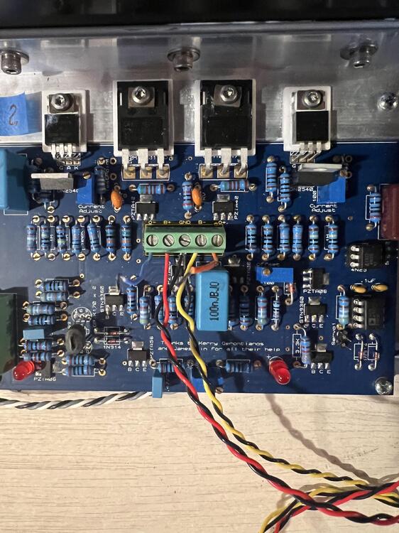
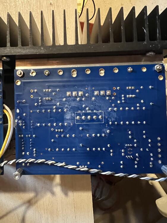
Checked the voltage across the zener diode (in parallel with the offset pot and tail resistor, which is 121R). Got ~6.8V on both boards. The CCS across the 50R was still at ~17.5mA (~0.875V). PZTA42 Vce on the good board was still at 13.2V or so, the bad board at 6.8V. I ohmed out the pair of 150K resistors. On both boards they behaved similarly, when ohming from the top of the string to ground both acted as a cap charging (which should have been 300K to ground). I'll keep looking, but any more suggestions welcome. I uploaded pics of top and bottom of the board.
-
OK, thanks. I'll check that for ~9V.


