Pars
High Rollers
-
Joined
-
Last visited
Everything posted by Pars
-
Ahh, so that's what the software is for... now onto the maths! Very cool!
-
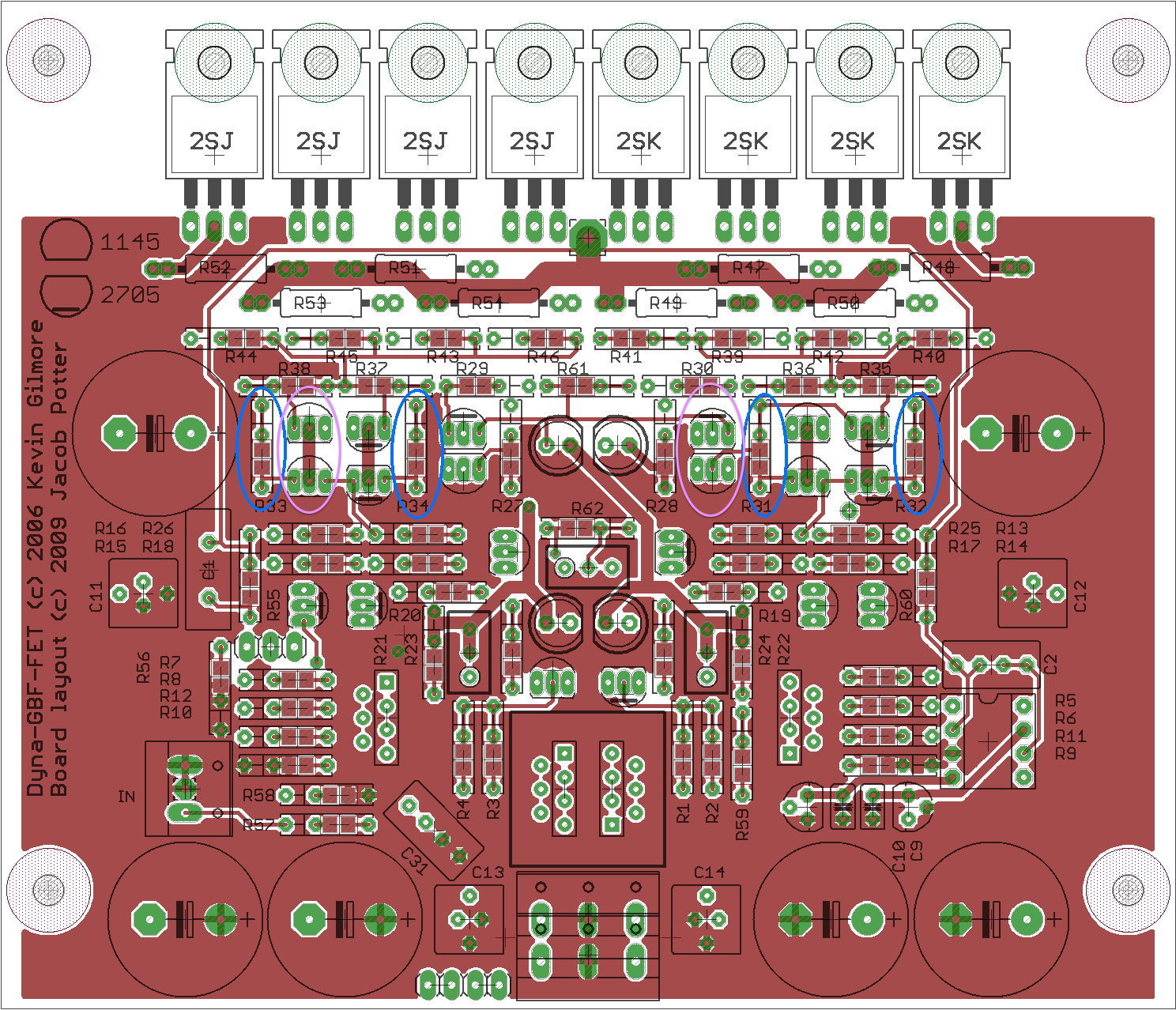
One other thing, some of the transistors in the diamond buffer section are running quite warm: Q26, Q23, Q18 and Q17 (purple ovals). Q26 is running ~60*C, and this is open air. I have some of the EDM sinks, but they push the transistor leads closer together than I like them. I also have some To92 heat sinks that I might try. DynaFET_schematic_marked.pdf
-
Katz may be very successful and experienced, but I've never heard of him, other than innerfidelity. Then again, I don't really listen to jazz, which going back to his reference recordings, seems to be where he exists. This isn't the first of his articles that I have read; guess he's just not my cup of tea. My undergrad is in music (percussion performance) and I spent quite a bit of time playing with symphony orchestras. I'm well aware that different examples of the same acoustic instrument sound different. My idea of a natural sounding recording would be this one, which in my opinion (and my brother's (trumpet)), is a recording that sounds to both of us like the CSO in orchestra hall, back when they had a phenomenal brass section (Herseth/Jacobs, et. al.). That said, I would rather listen to a so-so recording of a great performance than a SOTA recording of a so-so performance.
-
Just a bit more regarding the first paragraph: I haven't removed the ferrites as they were one of two things which killed the oscillation that I have tried, the other being output zobels as Amb describes in his B22 write up. Sent from my iPhone using Tapatalk
-
Yeah, so what? All this tells me is that he is used to processed sound. They don't normally try to make a band or performer sound just like they do in the studio, but better. Hence auto tune and all sorts of gimmicks. His "beloved O2" also colors my view a bit though I do trust Tyll's reviews and would probably buy something based on his recs. Sent from my iPhone using Tapatalk
-
Can't edit the sheet on my phone. Could you double my qty of unbal/bal and buffers (SMT) to 8/16? Thanks! Sent from my iPhone using Tapatalk
-
Yes they're needed. But haven't tried removing them. Knock on wood, I think I have a working board. I can get it to oscillate, but only with phones plugged in AND meter(s) connected to the ballast resistors. Pull the meters and it quits. I am going to put the gate zobels ala Cordell in but need some parts. 1) tried the mid feedback point and really bad oscillation. 2) the mid feedback point doesn't control gain (rail to rail). My spice sim confirms this unless I am configuring it wrong. 3) I am going to run RMAA on it w/Dynahi for other channel. That will hopefully give me a better idea if there are bad things going on that I am not seeing on the scope. 4) I had the input wiring reversed. Works much better now [emoji4]. Boards aren't marked for shit. The @!?# black solder mask makes it very difficult to see the traces as well. 5) note to anyone messing with these: the power connector is reversed from Dynahi. Sent from my iPhone using Tapatalk
-
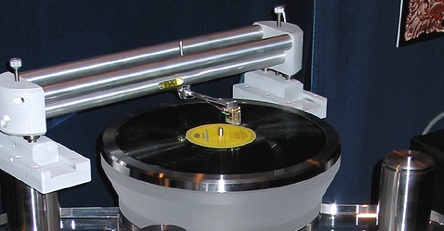
I see the micro hanging on the USB port... what is this and the software for? Cool project? What kind of TT?
-
Yeah, that is really nice! Reminds me of a Seiko I had years ago, though yours is nicer. Sent from my iPhone using Tapatalk
-
Replaced the 221R gate stoppers with the original 47R. I had previously switched to some ferrite beads I got from Arrow (Fair-Rite 2773009112) and still no sign of oscillation. I put in the other set of FETs (4 total now) with beads and 47R gate stoppers. Still looked fine. On listening to it, I decided I wanted to isolate the R channel (DynaFET R, Dynahi L) and discovered that both channels were still playing with only the R input connected, so I need to figure out what is messed up in the input wiring. Probably why when it was oscillating, it appeared on both outputs. Oops. EDIT: Biased at ~150mA per device pair. Bias starts at 320mV and drops as amp warms up. 2R ballast resistors. Sent from my iPhone using Tapatalk
-
Cool! Sent from my iPhone using Tapatalk
-
Happy birthday Dan! Sent from my iPhone using Tapatalk
-
-
I would question his reference material as well. To me, reference material is something like a symphony orchestra in a hall that you have been in and know. For his material, was he at the recording sessions and knows what it sounds like? His reference system also seems to be over processed. Must be a lot of a/d/a going on there. Sent from my iPhone using Tapatalk
-
Happy Birthday Al! Sent from my iPhone using Tapatalk
-
I've never had problems reworking 1oz boards (several cycles) if they are quality fab boards. 2oz is probably better though I don't know if 2oz is bonded to the substrate any better than 1oz is. I guess the additional copper must have some effect. Today's boards are a far cry from some of the '80s shit, where traces would lift if you looked cross-eyed at them Sent from my iPhone using Tapatalk
-
Checked the actual board (marked the same as yours Kevin, from the group buy, lovely black soldermask), and the 2 electros up by the MOSFETs run from V+ to V-. I'd have to refresh my memory on bypassing, as I recall this being done with opamps before, but I would think to gnd would be better? Still running 1 pair of devices, removed the 1K gate stopper and put sockets in. With 221R everything looks fine, other than it is resembling lampizator construction technique. Marc: thanks for the Cordell link. I read quite a bit of that, plus took a look at his book on amplifier design. It appears that he always uses gate zobels consisting of 39pf->100R->gnd on his amps. He seemed to indicate that he always uses them.
-
Very clean soldering work John! Nice! Did you do any matching?
-
No no Steve... some of us might like to see what kind of fucked up shit he is up to these days
-
Yes, but it takes a $200K table to run a high $$$ cart into the label...
-
^ I'll have to check the actual board. The Eagle files I have, which are not quite the final board. show the two 220uf/100V as going from V+ to V-. I've been trying to update the Eagle file so it more or less matches. The combo SMD/TH resistors he created are a massive PITA in this though, requiring 2 connections on each end.
-
-
Happy Birthday Steve!
-
Sure, I'll give it a try. I noticed that Borbely was using 100R or 221R on these devices. Any thought on the zobel fixing this? Band-aid? Cheating?
-
More interesting. I pulled 1 pair of devices. Still oscillating. Actually, now it was oscillating with the volume all the way down, would quit when turned up slightly, then back to oscillating as volume went up. Pulled the replacement 2SK214 and put one of the originals back in. Still oscillating, same as before. Pulled the ferrite chips I had put in and replaced with a couple of these: http://www.digikey.com/products/en?keywords=240-2437-1-nd Not oscillating! Hmmm. Of course Digikey doesn't have those anymore and I don't have 8 of them (5). Shit. Looks like I ordered 10. Will have to see what I used them in... flea clock boards probably.