Pars
High Rollers
-
Joined
-
Last visited
Everything posted by Pars
-
RIP Gregg... this year seems like a continuation of last year
-
Maybe posting pics as was requested would have helped? Hint: For anything other than small pics, a free photo hosting site such as Photobucket, etc. makes this much easier and allows larger pics to be posted.
-
That had occurred to me Kevin, thanks! I might go with that. masamoto: no, nothing wrong with that. I usually am more interested in relative to ground to see the balance between +/- though.
-
^ Looks good. Interesting measurement technique with load from V+ to V-. Mounting pass devices to heatsink For the GRLV for my dynafet, I need to mount the pass devices to one of the heatsinks. Since I am using a modushop/hifi2000 3U pesante, the mounting rails for the heatsink are preventing me from getting the GRLV close or right up to the heatsink, and I think the distance is more than I care to bend the leads for the MJW21193/4s. Since the amp boards are drawing ~0.8A, I don't think that mounting these to the bottom panel is sufficient. Should I: Go ahead and bend the leads Drill holes in the mounting rail to accommodate the standoffs and position the board close to the heatsink Shorten 2 of the standoffs by the thickness of the mounting rail so it can sit on top of it Remove the standoffs by the heatsink and let the output devices support that end of the board I don't have any angle brackets wide enough for these devices, and there is not any provision on the PCBs for these anyhow. Pics of how you have done it appreciated! I did look, but didn't find much with this case type problem.
-
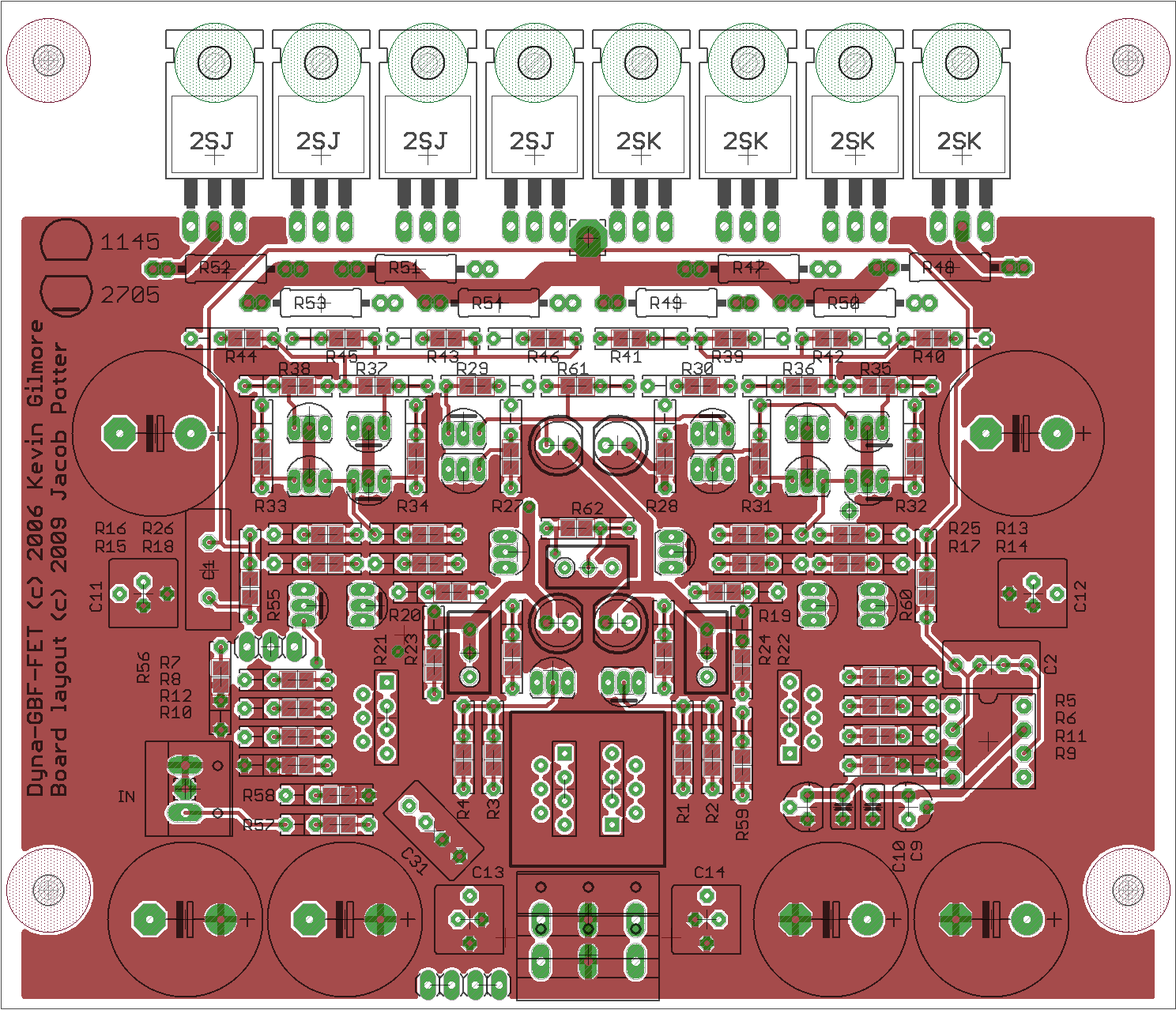
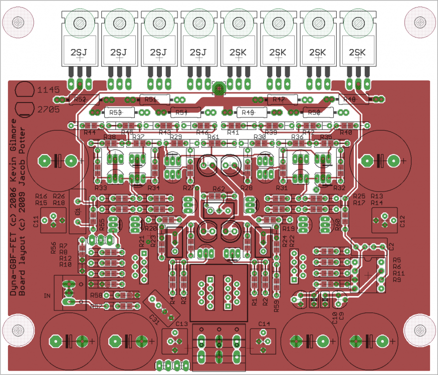
This is what I currently am running, schematic-wise (other than ferrites). Extraneous bits remain (I think) at the input in the schematic. Also the rail bypass caps don't accurately reflect what I have currently in place. Mine has 4x470uf 50V by the power input and 2x220uf 63V up by the output devices, modified to run rail->gnd instead of the original rail->rail. I also have 4x22nf Vishay MKP1837(?) in the C11-12-13-14 positions. Maybe should replace these with some Wima 4.7uf? Gain resistors (R55/R56) are 10K/2K in mine (10K/1K also verified). 4.7K/1K for reduced gain caused oscillation (without the output zobels of 47n/22R in place). The original 1K/100R did not work. I'm not sure if the ferrites should be accommodated or not in the PCB layout. Choosing which ones might take a bit of work as well. The chip SMD beads I had didn't do shit. The changes I made to mine were band-aids to get it to work. No scientific effort was expended to optimize parts such as the gate stopper values (47R PRP on mine). Cordell always seems to use the 39pf/100R combo for gate zobel or bypass, but that might reflect him always using a particular FET? Not sure. Mine are 33pf/91R, as that is what I had. I'll have to check the 33pf to make sure that is what is in there. As for FET output devices for a modern SS DynaFet layout, some interesting threads on diyaudio: http://www.diyaudio.com/forums/headphone-systems/207578-thor-all-discrete-lateral-fet-headphone-amplifier-17.html http://www.diyaudio.com/forums/solid-state/193730-transistors-recommended-new-designs.html http://www.diyaudio.com/forums/headphone-systems/263785-replacing-power-mosfets-sds-labs-headphone-amplifier.html dynafet_cby.pdf
-
Initially it would seem to be heat related, perhaps one of the output or bias devices cooked and is now unreliable? This dual build would seem to have some inherent problems with potential thermal issues. I guess I didn't look closer, but in this build, only one amp is powered at a time? Including the PSUs for that amp?
-
By new board, would this be a balanced (and SuSy) board? What changes to the original circuit would be made? The gate zobels? Output? I might be interested in a layout, though I have been making changes to Jacob's original SE layout to beef up trace widths a bit and add the aforementioned. My copy of Eagle is right at the edge of board size with this, so hampered a bit. After the SuSy Dynalo (which I like, don't get me wrong), I'm not sure I am a balanced believer. I don't hear full, if any, superiority to my original dynalo built on one of justin's headamp boards. Maybe if I had a fully balanced chain. Or better source. Or better phones. Dunno.
-
If you have some clip leads (micro or mini grabbers), can you monitor the bias with the lid on? When you say the problem now happens on a cold start, this is with the amp casing closed up? EDIT: this is on your combined SS Dynalo/Dynahi build I take it?
-
And why all the amp models? How about one done right and works? I guess that doesn't drive the upgrade business model well though...
-
There were still 4x470uf (2 per rail), but these were close to the power input. The lows were there, just not as nice. I still have a hard time believing that yours didn't oscillate. Mine did as soon as I put more than 1 pair of outputs in, sometimes with only a single pair (Renesas 2SJ77/2SK214). Yours was running 4 pairs from the picture I saw. Did anyone try the balanced board? Maybe the only run of those was with lil knight and no one ever got them...
-
Nope. At least that my scope can see (Tek 150MHz). DC offset is rock solid (another clue to possible oscillation if it is bouncing all over the place). Could run this without the servos if I wanted to.
-
Continued working on this. 1. I added the zobels aka Amb on the board outputs. Because I have a protection board installed, I put these on the amp boards rather than at the output jack. 2. I cut traces and reworked the two 220uf caps from V+ to V- to instead run from either V+ or V- to GND. 3. Redrilled and tapped to place both amp boards on the right heatsink, with the left reserved for the GRLV when implemented. While doing (2) above, I ran the amp without these caps installed for a few days. Without the caps installed, the amp lost some of its bass slam (one of the things I liked about it). Reinstalling the caps brought this back. I couldn't really pinpoint a sound difference between having caps rail to rail vs. rail to Gnd. Another artifact of this seems to be better highs response. Not sure if that had to do with the cap change or the zobels (output->22R->0.047uf cap->Gnd). I'm quite satisfied with the sound of this after these changes. Seemed to bring a slight bit more clarity and finesse to the sound. Soundstage depth and height seem to follow what is on the recording accurately. I may at some point try running this with a single set of output devices. Sent from my iPhone using Tapatalk
-
Happy Birthday! Sent from my iPhone using Tapatalk
-
Happy Birthday! Sent from my iPhone using Tapatalk
-
Probably not much, plus being Lithium I would worry about someone mis-identifying them. Sent from my iPhone using Tapatalk
-
His family is disputing the report awaiting toxicology tests. He apparently was prescribed an anti-anxiety drug and commented to his wife that he had taken more than his normal dosage and apparently slurred his words the last time he talked to her. Sent from my iPhone using Tapatalk
-
Thanks for the well wishes guys!
-
OK, color me confused. I had the 1-pole fuseholder/2-pole switch variant in my cart (DD11.0114.1110). Why would I want the one for 2-pole fuseholder (DD11.0124.1110) if I am only fusing the hot (line)? The fuseholder I had in my cart was a 2-pole, I suppose if I went with the 0114.1110 I would want the 1 pole fuseholder 693-4301.1405, without a voltage selection switch? Schurter's application notes (lack of) leaves a bit to be desired, and of course, I'm an idiot
-
Soren or anyone, So with one of these, and a dual primary transformer (0-110-110), you can switch voltage from US 115 to Intl. 220 with just the correct fuse drawer? For US use, I have a 693-4301.1014.03 fuse drawer in my cart as well (I think this one has the voltage selector for 110/220). For the US, I believe we only fuse the hot and not the neutral. Does this look like what I want? Thanks!
-
RIP Chris. Never did see him with either SG or AS or solo. 52. Way too young.
-
I'll take a look at them, thanks! I thought with some of you looking at cheap Chinese DACS, etc. that there might be some decent test gear out there as well. Sent from my iPhone using Tapatalk
-
Oops. It hadn't dawned on me that these are mainframe plugins. As nice as they are, I don't have the space to deal with a mainframe platform. Sent from my iPhone using Tapatalk
-
I guess I would like something just for audio testing (view on scope). Something that can do sine and square waves, sweep would also be useful. My thoughts revolve around testing stuff like the DynaFET for oscillation by running various frequencies thru it. Testing above 20kHz might be useful as well; don't think I can do that with the PC setup right now but hit sure. Sent from my iPhone using Tapatalk
-
Any recommendations for one, used and cheap preferably? (I know, non-HC). I was looking at a couple of B&K 4011s or maybe an HP3311a? Other? Or am I better off using a PC with my mAudio box and a program (can't remember which one I have, but it isn't bad).
-
Yep, RIP. Great in a lot of roles. Tombstone was another one. I also recall some movie where he was a B52 pilot in a nuclear war, didn't drop his bombs and just flying around waiting for fuel to run out at the end (world destroyed). Dawn's Early Light or something like that? Sent from my iPhone using Tapatalk