-
Posts
8,474 -
Joined
-
Last visited
-
Days Won
7
Content Type
Profiles
Forums
Events
Everything posted by Pars
-
Don't quite understand your question? At any rate, the ground lug from the TRS jack should go straight to PSU ground (sigma22?)
-
I'd go for that Michael, but took a look and don't have any more blanks. I do have a built-up one with Roederstein resistors, all devices socketed with Mill-Max pin sockets. That one has some sentimental value to me The original transistors that I had (have) weren't that bad between N and P. I do have a pair of original Dynahi boards, as well as around 5 of the original Dynahi PSUs. Also, a couple of cetoole discrete I/V boards, some amb and KG protection boards (with my mods), etc. Oh, and a pair of DynaFET boards To vortaku: I would recommend using the modern SS layout, using current parts. Many of the parts for the original are somewhat unobtanium (Toshiba 2SJ74 2SK170 JFETs). You can get equivalent parts from Linear Systems, but the original transistors (2SA1015 / 2SC1815) aren't easily obtained.
-
I worked withDan Gardner quite a bit on this around this time, doing edits for the build guide, etc. I've never seen board files or gerbers for these, and I am pretty sure that Kevin doesn't have them either. Dan hasn't been active on these forums for a long time. Either we could contact him or I could possibly do a layout. I may still have a couple of boards but would need to look. Sent from my iPhone using Tapatalk
-
Hmmm. I would probably start by swapping the input wiring (pot to boards). If the noise moves then it has something to do with that. Otherwise go over the board (components and location correct? Solder joints?) Sent from my iPhone using Tapatalk
-
Happy Birthday! Sent from my iPhone using Tapatalk
-

and now for something completely different part 3
Pars replied to kevin gilmore's topic in Do It Yourself
Interested in building a single-ended CFA2 (or is that CFP2)? Can't find the schematic matching the cfp2gmt board files on the archive... I have the cfa2.pdf schematic, but it doesn't match the board file. Maybe I'm not looking for the right name here... Also, what is the board size on these? I'll have to admit I am having a hard time following this thread and all the loops and progressions from se to balanced to power amps... -
RIP Gord Sent from my iPhone using Tapatalk
-
Door stops can be expensive... Sent from my iPhone using Tapatalk
-
Happy Birthday! Sent from my iPhone using Tapatalk
-
Happy Birthday! Sent from my iPhone using Tapatalk
-
Happy Birthday! Sent from my iPhone using Tapatalk
-
Only the input - channel should be tied to ground, NEVER the output - channels. In effect you would be shorting the output devices to ground which probably wouldn't make them very happy:) For SE output only the + signals and signal ground should be used. That said, on my SS Dynalo Mk2, I have both RCAs and XLR inputs, with a toggle switch to tie the - inputs to ground for SE input via the RCAs. I don't hear a difference when using SE input and unshorting the - inputs via the switch. Maybe I need to listen more closely? Sent from my iPhone using Tapatalk
-
Well sure he "sacrificed" Birgir... a lot of people's money. Sent from my iPhone using Tapatalk
-
Hmmm... "once I had been able to establish a robust company with excellent products." Guess that never happened... Sent from my iPhone using Tapatalk
-
For both Jose and penmarker: if you are only using an ss dynahi in SE mode, why even populate the - channels? All they are doing is burning power... Even then, the - inputs would be tied to ground, as done in the original dynahi /dynalo. Sent from my iPhone using Tapatalk
-
Use a 5 pin XLR and ignore the Sony bullshit Sent from my iPhone using Tapatalk
-
Your hand drawn diagram above appears to be correct, and does the same thing that the Neutrik RCA->XLR adapters do (tie the - signal to gnd). For wiring interconnects, etc., many tie the shield to the - side conductor, sometimes at one end only (telescoping ground). This is for noise rejection. For the pot wiring, if looking at most pots from the front with pins down, the furthest R of the 3 pins per gang is the input, and equates to the signal in your drawing on the left side of the pot. The middle pin is the wiper, and equates to the right side of your drawing. The pin furthest L is the gnd or common pin.
-
Haven't seen the ad, so didn't get the reference...
-
An engine doesn't REQUIRE power, it MAKES power. Not sure what you are trying to get at with your quote...
-
Appears to have the usual items necessary to generate hype: 1) fancy case - check 2) bullshit bingo laced ad copy - check 3) high price (so you know it's gotta be good) - actually not too bad at $1400 Sent from my iPhone using Tapatalk
-

stax mafia circuit boards see updated links on page 5
Pars replied to kevin gilmore's topic in Do It Yourself
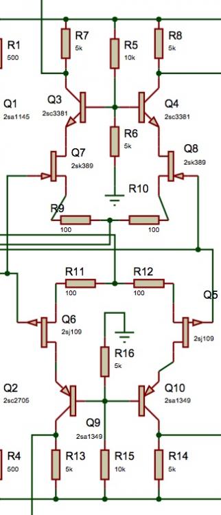
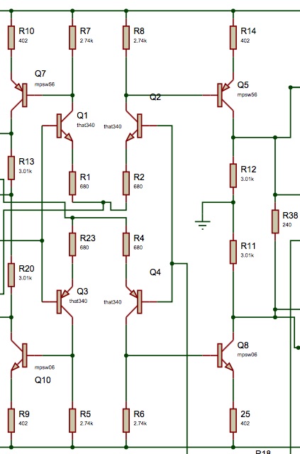
Thanks Kevin, The SuSy architecture must be fairly subtle in terms of it versus your normal differential balanced. Here is what I had for a schematic for the dynafet balanced vs. the SS dynalo (input sections only): I'll quit crapping on the stax mafia thread also. -
A bit curious about this one (agree with the rest). You're talking about the ground pins on the pot (1 per gang)? Pots work basically as a voltage divider with a resistance from the input to the wiper, and another from the wiper to ground. Not connecting the ground leaves this resistance floating. I always run these to amp ground (Not chassis). Sent from my iPhone using Tapatalk
-

stax mafia circuit boards see updated links on page 5
Pars replied to kevin gilmore's topic in Do It Yourself
Are the SS DynaFet gerbers available? Couldn't find at the link in spritzer's 5/10 post, nor Kevin's 9/4 post. Were the balanced Dynahi and FET boards done in 2011 for Lil'Kinghts GB the SS versions? They look like it, but I could be wrong... I attached the schematic I have. What FETs were these targeted for? The BOM he had showed 2SJ76/2SK213s, but for some reason (availability), I thought the last version used something else? dynafetschembal.pdf


