-
Posts
8,475 -
Joined
-
Last visited
-
Days Won
7
Content Type
Profiles
Forums
Events
Everything posted by Pars
-
Looks ok, but that probably wouldn't cause an issue anyhow. Check to make sure all the bridge diodes are oriented correctly.
-
I'd noticed the same thing Michael... I think the newer boards with 3 bridges have all the bridges oriented the same way. I think the older boards like we are using had them reversed.
-
I've never tried paste before but was going to order some on my next Mouser order (Chip Qwik 910-TS391AX Solder Paste No-Clean 15g Sn63/Pb37 T4). I was asking about heatsinking the onboard regs (not offboard). Also, for the offboard regs, any reason to use Amb's sig78/79 over some from ebay, such as seller LDOVR's (though I see he wants $220+ for the neg reg now
-
I'd be interested in some as well. I presume these would have the same limitations in terms of voltage range as the normal GRLV does? Could you do 5V, etc. with these assuming the reference, etc. were changed?
-
If going with the onboard regulators, do these need heatsinks on the top of the board? If so, what, and how to fasten?
-
Yeah, I know Marc, but better to use as designed. And wouldn't help here as you note.
-
It's too bad that Toshiba screwed up on the pinout for the SC3381/SA1349, and an adapter like this would NOT work for the SK389/SJ109 JFETs, even though they are the same package. I know, the JFETs are rarer than hens teeth, but still. The dual JFET adapter can be done with quite short traces, nice and clean...
-
Ooh, didn't realize Season 4 was out already. Need to get on this...
-
Doesn’t sound much like a GRLV... EDIT: doesn't look bad at all. Larger, but I for one could use the additional outputs. I didn't verify the schematic either. Board is 116.8mm * 147.3mm
-
Any recs for a hot air rework gun/kit, cheap? Looking at some of them on eBay. It won’t get a ton of use so no need for a really good one, just something to get the job done. Sent from my iPhone using Tapatalk
-

Even H2 headphones with personalized ‘Earprint’ signature
Pars replied to jvlgato's topic in Headphones
Glad to hear John! We'll have to get together soon so I can get your remote back to you. -
And who are you? Very cool Jose!
-
Happy Birthday!
-
Happy Holidays to all! I hope 2018 can only be better than that thing called 2017
-
Happy Birthday Ken!
-
"More than 20,000 people have been using our product" And 100 billion flies eat shit... your point is?
-
The outlines are in 21 tPlace in Eagle (where they should be). They are in the top silk layer in Diptrace (and not the top assy layer). The parts appear correctly in the Preview in Diptrace. A person from SeeedStudio replied in an email not to worry. The gerber viewer sometimes has issues. Sent from my iPhone using Tapatalk
-
Guess I should look at the neg regs datasheet. If the pads are all connected together on the board, the solder bridges on those pins won't hurt anything.
-
It shouldn't unless you decide you wanted to change voltages.
-
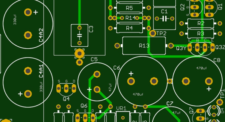
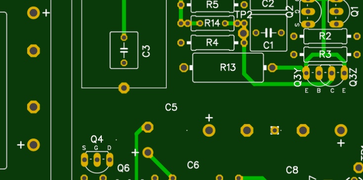
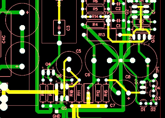
Sorry to dredge up an old topic. I have started using DIptrace again (3.2.0.1), and am getting along with it (more or less). However, when generating Gerbers, some of the top silk is not appearing when using gerber viewers such as the one on SeeedStudio's site (or gerber-viewer.easyeda, which appears to be the same engine). Specifically, electrolytic cap outlines aren't shown. If I view the gerber file in some other gerber viewers (gerber-viewer.com or CircuitPeople's) they appear OK. Viewing much of the same board, done in Eagle, appears fine. Any thoughts? I imported the schematic and parts libraries from Eagle, but did the layout in DIptrace. The parts in question did come from an Eagle library, but replacing one of the caps with one from Diptrace didn't seem to solve the problem. Some pics: This is a gerber from Eagle, on seeedstudio's gerber viewer This is a similar board, only from Diptrace: And finally, the same board from Diptrace, but this time using gerber-viewer.com
-

and now for something completely different part 3
Pars replied to kevin gilmore's topic in Do It Yourself
They aren't nearly as good about this stuff as they used to be. They offer next day shipping as a carrot, and then take 3-4 days to ship the order. My last order, I called and spoke to one of their reps and asked why an order submitted on the weekend had not shipped by late Monday. This was an $80 order. The rep said "with a large order like yours...". Precious, but I told her it was a small order, and that their commercial clients, etc. (and peeps like Doug) place much larger orders than that. Now they did immediately ship the part I got them to add to the order... -
I think you meant XLR inputs, not outputs? You could just wire the XLRs and use the Neutrik adapters, saving yourself the switch and the wiring of it.
-
Very nice Jose! I take it that is input switching back by the jacks? Is the other PSU back by the transformer for a momentary power switch, or is that just for the input switching? It looks like some thought went into this layout and good job on the wire routing, etc.
-
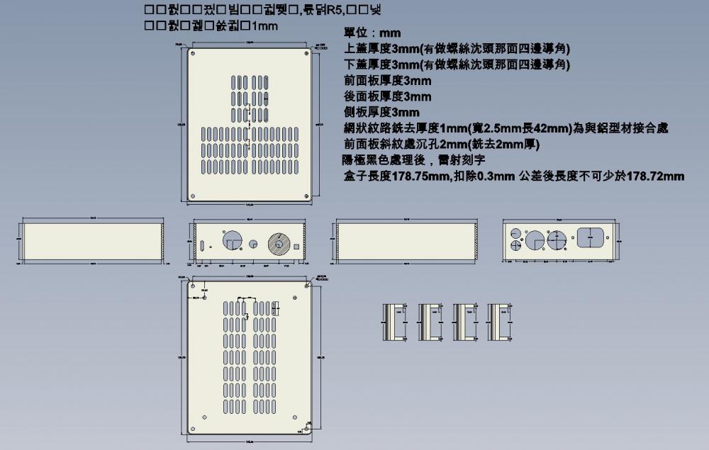
Took a look at the dwg file tonight using Fusion 360 and also the SolidWorks eDrawings app. One thing I noticed is the corner blocks don't seem to show drilled/tapped holes on them. When I look at in the SolidWorks app, there is some Chinese writing (I presume), which of course I can't read. Are these instructions to whoever is making the parts for you? Here's a screenshot from the Solidworks app:
-
Thanks! I actually have Fusion360 on my Mac but haven’t spent the time to learn how to use it yet. Any recs on tutorials for that would be helpful. I’ve never used any CAD type programs... closest would be things like Eagle, etc. Sent from my iPhone using Tapatalk


