-
Posts
8,474 -
Joined
-
Last visited
-
Days Won
7
Content Type
Profiles
Forums
Events
Everything posted by Pars
-
No more up to date schematic. When in doubt, follow the board markings. Sent from my iPhone using Tapatalk
-
The point at 9 is 4.1815V (L) vs. 4.0713V (R). I believe this is about 0.25dB (0.23). It was definitely audible but was at the point where I initially was wondering if I was hearing things or not This is in a known amp; the TKD 4CP601 I was using doesn't exhibit this behavior, nor does a 2CP2511 25K pot I also have. I don't know if partsconnexion will do anything about it (or TKD), but I guess I will ask them and supply the data.
-
Shit, didn't even realize they carried them. That isn't too bad...
-
To give the wiring a better shot at shorting out against the case, hopefully before the owner realizes what a pile this thing is?
-
^Yep, thanks! I hooked up a 9V battery to the input-gnd and plotted 11 points wiper-gnd (around 15 deg rotation/point) and moved from channel to channel without varying rotation. They actually plot out pretty close. There is one point at around the 9th point where the L is louder than the R, which was probably close to where I was listening at.
-
^ https://www.head-case.org/forums/topic/13242-dynalo-mini-enclosure-group-buy/?do=findComment&comment=786111
-
I bought a TKD 2CP2500 10K from partsconnexion awhile back (when they had their 25% off sale) and just installed it yesterday and did some listening. There seems to be a channel imbalance. Any suggestions on how to run a curve on this to compare channels? Or is it simply compare and record ohm values at individual rotations at various intervals? Would I only be interested in wiper to gnd, or do I need input to wiper values as well?
-
Looking at ebay, this one popped up: https://www.ebay.com/itm/OKi-SmartHeat-PS-800-Single-Port-Soldering-System-Kit-Pen-Tip-Holder-PS800E-OK/132491900159?epid=2238602788&hash=item1ed921f4ff:g:Cl4AAOSw9p9adI3M It doesn't seem complete... what else would I need? This one does seem complete though: https://www.ebay.com/itm/OKi-Single-Output-Solder-System-with-SmartHeat-Six-Solder-Tips-BRAND-NEW/192469300137?hash=item2cd01073a9:g:vfsAAOSwOFBaiDfI
-
Sure, I'd love a Metcal and I'm sure they are better than the Hakko I have. They also seem rather pricey, even on ebay. Also difficult to tell if you are getting the full soldering station or not as most sellers seem to sell everything separately.
-
I just looked (way) back. Amb apparently uses 2oz copper on the beta22, sigma22 and CK2III boards. The Dynafet boards were also 2oz copper. AFAIK, all of the prior GB boards (imagineering) were 1oz boards (the old Dynalo rev B and C boards, the original Dynahi, etc.) I'm not in for any dynalo mini boards, but this is from the experience of building 3 of them, plus talking to Kerry. I may fuck around with one of the spare boards I have and some new parts (which I still have). Reflow oven seems to be the best bet and I may commandeer the toaster oven briefly again. This worked pretty well for putting the tantalum caps on the underside of the last board I did. Even with my Hakko 936 and a 3.2mm chisel bit, cranked up to 750F +, I had to use a hot air rework station to get some of the connections to ground to flow well.
-
As for board copper weight, I believe it is based on trace width/cross section and current capability, but I could be wrong.
-
Hehe! These are being sold as Mjolnir Audio? Or did they just "use" your pics?
-
I think they are still talking 2oz for the group buy. I don't know what the basis for the current moar is better philosophy on copper weight is. All of the older GBs (dynalo, dynahi, etc.) were 1oz boards, many of which I have reworked several times with no problems. Some boards need the heavier copper (Stax stuff, the GRLV/GRHV). Most don't.
-
The links I posted above will take you to the current files. cfa2cmirror is the schematic and the latest edition of the CFA2, and is the basis for the boards in the GB. Kevin changed the servo layout and how it feeds back into the amp as some of us found the servo in the original to be audible. I've attached the original CFP2 BOM, and a BOM for the GRLV. I don't recall whether I updated the CFP2 BOM for the latest, but it should be close. The original 1 ohm resistors were wirewound; this BOM has the 3W Vishay metal film in it which is a better choice. CFP2 BOM.xlsx GR LV BOM_Sep26.xls
-
Agreed. I know mypasswordis and cspirou were two who managed it. I was trying to use the advice I got from mypasswordis in my last attempt. I would think the lighter copper weight on the GB boards would make this more doable. Many of the pins on the regs go to ground, and on the 3oz boards, difficult to heat. Kerry's prototype board that he did was 1oz copper, and he told me via pm that he doesn't think the board needs to be any heavier than that. I would agree.
-
I messed around on another board without any success (had a couple extra that I had forgotten about). The chip may be fried after my earlier attempts as well. I kind of lost interest in it also, probably doesn't help.
-
I seem to be the only one participating in this thread... hmmm Just got the heatsinks today (45x35mm). After reading what some have said regarding the heatsinks tunneling heat down the transistor rows, I'm considering drilling 2-3 holes in the heatsinks along the rows to allow them to vent. I'll run the thermal heatsink tape in rows just on top of the transistors. Anyone think this is a bad idea?
-
Stay warm and safe. Looks nasty, though my wife would think it was pretty (other than the downed limbs)
-
Paid. Thanks!
-
This is the schematic. As for your other questions, look at the golden reference LV thread and the "And now for something completely different" thread. That thread devolves into discussion of two or more amps. As far as build threads, there aren't any, nor are there guides, etc. You have to read the threads and take your best guess on some things. Kevin retired from Northwestern University, so none of those links work. The current archives are here: Documents: https://drive.google.com/drive/folders/0B7egryukiT7_TFlEQlBRejdVdDQ Gerbers: https://drive.google.com/drive/folders/0B_iJFfZStuVhSE5nOHBVdTByR1k cfa2cmirror.PDF
-
Happy Birthday!
-
Thanks Gael. Are the 4 corner screws going to be countersunk? Also, would you consider offering versions of the fronts/backs with countersunk screws for those of us who aren't going to use the Neutrik screws?
-
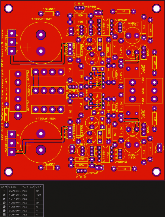
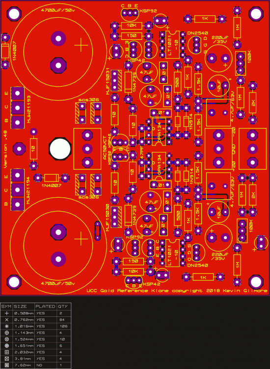
Here are gerber images of goldenreference6d: and goldenreferencelargecap: 6d may be closer to what people were looking for. The largecap version does not support the rectifier boards, but the TO220s rectifiers it uses are SiC diodes (which are schottky as well).
-
Don't think so. The one I posted above is the same as goldenreference6, but has dual outputs. The version with 35mm caps is goldenreferencelargecap.zip? That one has the 35mm caps, dual outputs. It is only setup for 1 bridge (center tapped) and TO-220 SiC diodes only. That one would be fine with me, but others may not want that one.


