Pars
-
Posts
8,489 -
Joined
-
Last visited
-
Days Won
7
Content Type
Profiles
Forums
Events
Everything posted by Pars
-
The jpg are the only schematics that Kerry provided for the mini. I may draw a set up if I have time, as the legibility of these leaves something to be desired. The ss Dynalo (and Dynahi) will handle any combination of input/output. 1) balanced in/balanced out 2) single ended in/balanced out 3) single ended in/single ended out 4) balanced in/single ended out If you opt for only a balanced output jack(s) you won’t be able to provide single ended out without some pre-planning. The mini as Kerry has defined it provides both a 4-pin balanced XLR and a standard 1/4” stereo single ended output. Single ended input loses ~6dB compared to balanced in. Sent from my iPhone using Tapatalk
-
The supersymmetry input section does unbalanced to balanced conversion. You can use either single-ended or balanced sources with this. For single-ended source, the - inputs should be grounded. You might try actually reading the thread... Sent from my iPhone using Tapatalk
-
Hi Gael, How long until you get the prototype? As for lead times, I guess I never asked when I was talking to CAM Expert, but I was under the impression that it would have been 2 weeks or less with them? John has ordered from them before, but shipping to Australia I'm sure takes some time I'm certainly no typeface expert. The fonts that John used in FPE Frontdesign were Asian 1 stroke (for the supersymmetry) and Euro 5-stroke for the Dynalo. He did do some manual kerning by doing the "D" and "y" of Dynalo individually and arranging the spacing. He used 10% incline to mimic italics. From your samples, I like the Hiragano Maru Gothic, but don't care for the Silom. I like the Gil Sans Bold but the all caps on the DYNALO is too much, particularly with that font. You might also look at Calibri or Futura if you have those (typical Microsoft Office stuff).

-
^ That (interface) was because they also copied the Cisco IOS (including comments and bugs). When I worked for Tellabs, during an optical tradeshow, we caught two of their engineers attempting to disassemble and photograph a piece of our equipment on the show floor after hours.
-
^ ouch! Those are expensive for what they are! I’ve already got what I might need from my last order from seeed, so I may drop those... Sent from my iPhone using Tapatalk
-
Happy Birthday Doug!
-
Yes. I won't share that one however. Let me clean something up and I'll send it to you. EDIT: see attached. Allows color selection for jacks, THAT340 or JFET, onboard or Amb regs (including associated parts). EDIT2: Replaced file; description wrong on 160K for Amb reg. Also note that the JFET selections chooses the TO71 package. The SOT223 package is a bit cheaper, so you would have to manually handle that. Also, many of these parts are small. You might want to order extra. Also, the Elna Silmics don't fit worth a crap, and didn't sound better (sounded worse to me). Not recommended. ssdynalo-v1-4 cby.xlsx
-
Ooops, yes should have clarified that On Semi is EOLing them. Sent from my iPhone using Tapatalk
-
After building the 3 minis, I’m not in any hurry to do any SMT anytime soon Though changing out the th caps on one board wasn’t any fun. Just got a notice from Mouser that the MBTA06/56 used on the mini is EOL. Now they are discoing SMT parts, not just TO92s. Haven’t checked to see what good replacements might be. Sent from my iPhone using Tapatalk
-
You can find most of these in the DIY section. Some hints on ones that won’t be obvious: 3. And now for something completely different 4. Dynalo Mk2, mini version (no sep thread for this one) 6. Std pot for Dynalo Mini, but can be used for many balanced amps 7. Schottky discrete rectifier board (GRLV) 8. Pot board with Phoenix and Molex KK connectors. Will work for Alps RK27 (blue), TKD 2/4CP 601 and 2500 pots 9. Use discrete transistors or FETs instead of the THAT340 chips in amps that use them Sent from my iPhone using Tapatalk
-
It’s always a good idea with these to start with the pots centered and incrementally adjust the offset out, then set the bias (IIRC correctly the adjustment procedure). You can get the pots approximately centered by using an ohmmeter and getting both sides to read approximately the same wiper to end terminal. Sent from my iPhone using Tapatalk
-
What was wrong in your biasing technique? Is this with the replaced resistors? What is bias set at now? Sent from my iPhone using Tapatalk
-
Look in the Stax thread for the current archive location. Sent from my iPhone using Tapatalk
-
OK I would measure them. Typ is 1.7V; max is 2.2V. We used to match LEDs for these, more important back when there weren't pots for offset. OK I've seen or heard of resistors being mismarked. Since you have the same problem on both boards, unlikely however (unless it is the whole batch of one value).
-
Doubtful that you fried any devices unless you connected the power backwards. When you say you replaced resistors with 340R, these were the 500R resistors? And those clear LEDs, have you verified their forward voltage as 1.7V with a meter? No PNPs where an NPN should be and vice versa? All resistors ohm out as their marked value?
-
Did a quick search back for copper weight and saw the 3oz recommendation. Ran across the special audiophool cable that blew up some poor guys actual KSA5 and found that those fucks are still in business! Revelation Audio Labs jeebus...
-
The PNP and NPN should not show low resistance (i.e., short) to each other. They will probably show some resistance, but I would assume it would be in the K ohm or higher range. None of the tabs should show a short to the L bracket. I couldn't tell in your pic what was under there or whether you had the shoulder insulating washers (such as Mouser 532-7721-7PPS). If the N and P were shorted together, you probably wouldn't be seeing approximately correct V+/V- (assuming the PSU was connected to the amp boards when you took your measurements), as they would be connected to one another via the shorted collectors. Just a shot from looking at the pics. EDIT: and I think Jose was asking if you had decreased the bias. Personally, IMHO, this amp is designed to run at 750mV/75mA bias, so that is what you should be running, and it shouldn't effect offset (i.e., you should be able to get the offset down into the sub 5mV range at that bias).
-
Very cool!
-
Should be the same... 0mV Sent from my iPhone using Tapatalk
-
What does V+ and V- look like? Also, with the amp off, set your meter to ohms and check continuity from each output device tab (tab, not the screw) to the heatsink. Also, check from a tab on one of the first 4 devices on the left to the tab of one of the 4 devices on the right side. Sent from my iPhone using Tapatalk
-
They should all be 0V, or very close. Ideally ~1mV or so without the servo. They will drift, so more realistically between +/-2mV or so, O+ and O- to Gnd. Inputs grounded or pot at 0. EDIT: looking at your picture above, what are you using to isolate the outputs from the heatsink bracket? Thermal TO220 pads are best for this; I would not depend on thermal compound for this. Also, it does not look like you have insulators under the screws for each device? The tabs on these are live (collector of each device) and MUST be insulated; whether you use nylon or PEEK screws, or steel screws like you are, but with the nylon step insulating washers. Sent from my iPhone using Tapatalk
-
Agreed, been watching it as well, and like it.
-
You probably should have something on there. Most people seem to mount them to the case bottom. On mine, which is uncased so far, I use a clip on heatsink like this:
-
sbeylo, it is the slots for the TKD CP2500 that you have to make sure they plate.
-
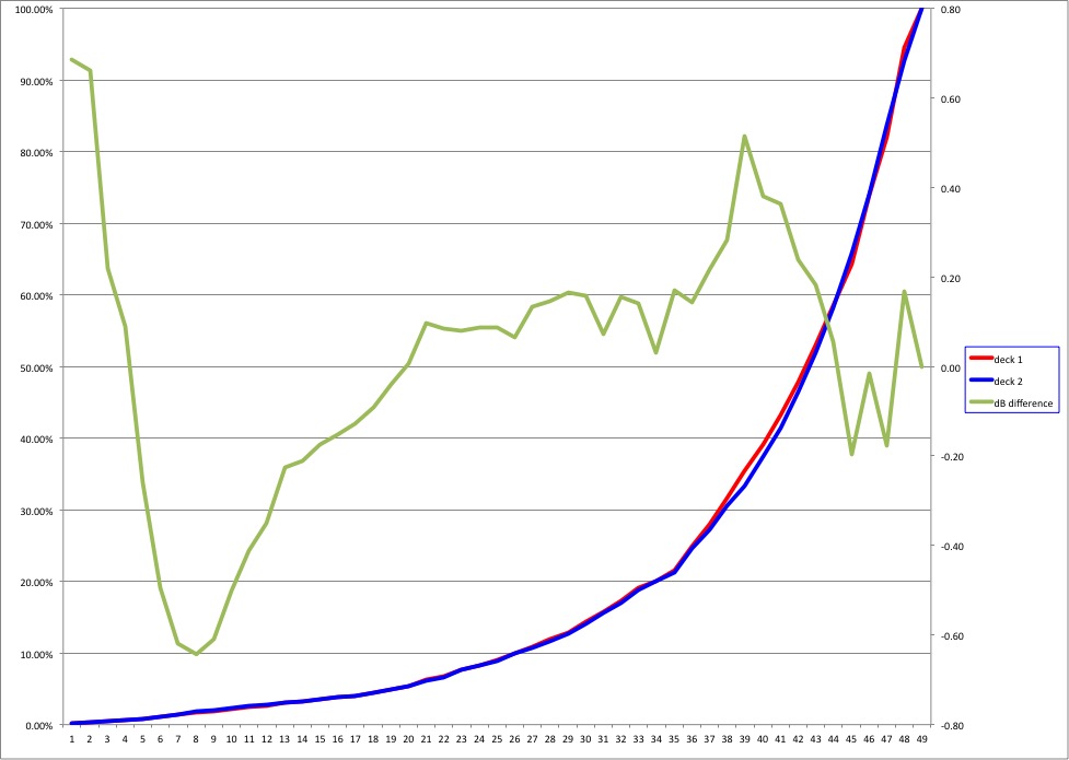
I ran some numbers yesterday at finer points and came up with this. I used a bench supply set for 1.007V (and had to adjust as I was running these to keep it there), feeding both deck inputs at once.. I used the same DMM on both sides (HP3468), moving the test clips at each pot position. I took the voltage from wiper to ground for each deck (V1, V2) and used 20 log(V1/V2) to calculate the dB difference. It was slightly above 0.5dB around the area that I was listening in (position 39). If I didn't do this correctly, let me know