Pars
High Rollers
-
Joined
-
Last visited
Everything posted by Pars
-
The link in the post from me quoted above was intended for Dynalo Minis only. Also, I never thought that stacking the amp boards like that was a good idea from a heat perspective.
-
Happy Birthday Craig!
-
That would seem to warrant a snowblower!
-
-
Sure, now that I have the board I laid out down to the original’s size Looking forward to it! Sent from my iPhone using Tapatalk
-
I would get a 465b instead of the 465 if you can find one.
-
^ this I’ve never really listened to Talk Talk much, might have to change that... Sent from my iPhone using Tapatalk
-
Happy Birthday Naaman! Sent from my iPhone using Tapatalk
-
2SA1968->taobao = likely fake Sent from my iPhone using Tapatalk
-
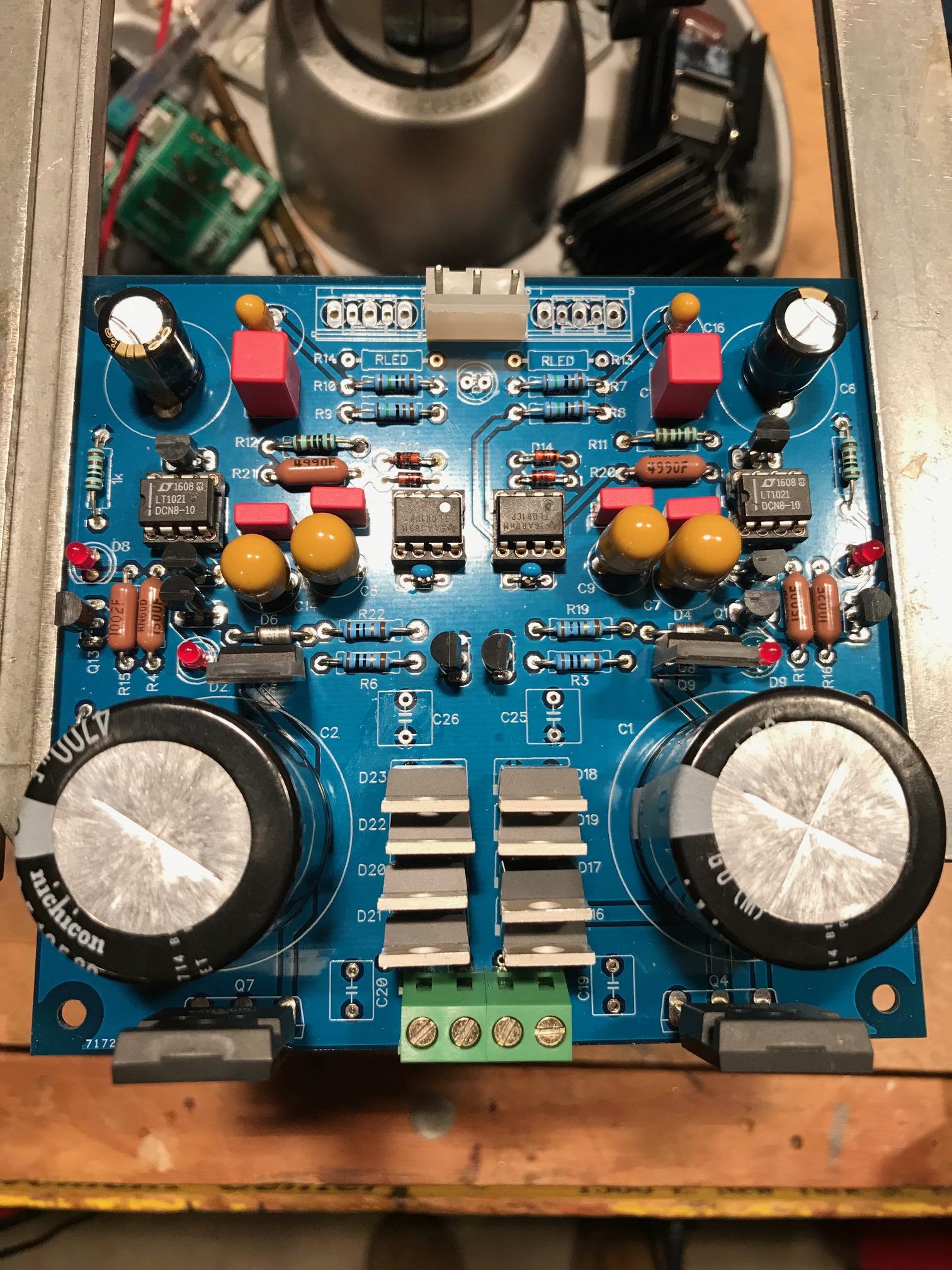
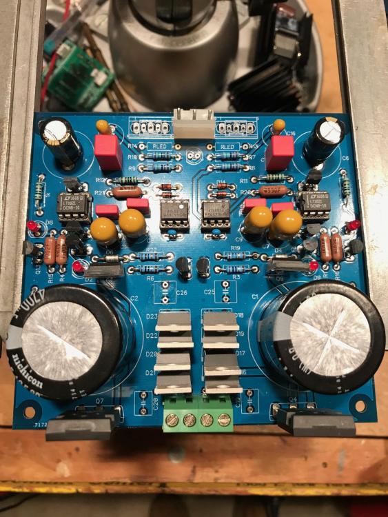
Here's a pic of the 35mm multioutput boards I had run. DImensions are 116 x 107mm, with the mounting holes on 106 x 97mm centers. On Semi schottky rectifiers, 30mm caps installed. I'm working on shrinking this down to match the size and mounting pattern of Kevin's boards (110 x 93 with mtg. holes 100 x 83), and so far it looks good, though I'll probably have to lose the following: power LED and resistors the current board allows 220uf caps that are 18mm diam. with 7.5mm lead spacing in the upper corners. Not sure what cap was the target here, as a Silmic is 12.5mm d x 5mm ls (for 35V). This will shrink to Silmic size (though I don't use them). This doesn't have the rail balance pot and stuff on it (to equalize the +/- rails). I'll take a look at that and see if it would fit. I'll probably ditch the 1uf film caps following the main filter caps. Not sure they are really of any benefit. These boards do support R-C snubbers. You could also do Mark Johnson's (diyaudio-Quasimodo thread) favored R-C-R snubber by soldering the 0.01uf film caps across the 2 AC inputs on the bottom. I may try to accommodate these on the board itself.
-
Bought a 2465A... hopefully its a good one. https://www.ebay.com/itm/183692541596 This was the one I was originally going to buy https://www.ebay.com/itm/TEKTRONIX-2465A-350MHz-OSCILLOSCOPE-TUBE-AUDIO/283374991066?epid=96991967&hash=item41fa7736da:g:jGYAAOSw~TNcP5sP
-
I guess that was something I had wanted to ask... that if the scope is working fine now, are you good, or can it die (like a dog*) at any time? I guess probably the latter? *sorry, been listening to early Curve lately Sent from my iPhone using Tapatalk
-
-
Yeah, Rigol was the name I was looking for. My Tek 465b needs recapping and a bit of cal, etc. The 2465 I was looking at sold (bastards!). Justin, PM me with what you would want for the 2467.
-
I know some of the newer and cheaper Chinese digital scopes are all the rage (Keysight, etc.) I am toying with buying a refurbed Tek 2465A, completely working, for a decent price. I know these have a proprietary IC in them, that if it fails, turns these into a doorstop (though I seem to recall this IC being available now...). Good idea or bad? For some reason, I've always wanted one of these... Flail away.
-
-
-
-
Happy Birthday Colin!
-
Happy Birthday Steve!
-
Hey Ryan, I'd definitely be interested in going. Chris
-
Yeah, Shar tools look nice. They’re only 10 miles from me and we go up to St. Charles fairly frequently. Sent from my iPhone using Tapatalk
-
Kevin retired from Northwestern a year or so ago, so none of those links are active anymore. Files are available here: https://drive.google.com/drive/folders/0B7egryukiT7_TFlEQlBRejdVdDQ Board files here: https://drive.google.com/drive/folders/0B_iJFfZStuVhSE5nOHBVdTByR1k Normally, the stax mafia circuit board thread, which is a sticky here, is where you find this stuff.
-
RIP actor Albert Finney. Always liked him and his roles. Sent from my iPhone using Tapatalk
-
Happy Birthday Jeff!