-
Posts
8,474 -
Joined
-
Last visited
-
Days Won
7
Content Type
Profiles
Forums
Events
Everything posted by Pars
-
Sorry to hear as well Todd.
-
Yes, I had considered doing this (insert DMM in amps mode in place of fuse) in order to estimate bias (@15mA should be 4 * (4 * 15) or ~240mA + a bit for the other circuitry). I thought this way I might be able to estimate the bias with heatsinks attached. Sound reasonable? Sent from my iPhone using Tapatalk
-
Ted had better lose... another pos that needs to lose is Nunes. Fucking traitor (among traitors)...
-
Understood... thanks for the data. Those are the other LEDs I have. I was thinking about trying the 402R with current C170 LEDs ( which I am getting 17- 18mA bias) and dropping the 255R down to 240R and see what I get when warm. One thing I don’t quite understand about the operation of these CCSes is the increase I see in bias of around 5mA or more between cold and hot. Is this caused by the LEDs being heated? Doesn’t seem very “constant” to me... EDIT: Put 240R in one channel. After warming up 30 minutes, it was right where I wanted it (290-304mV or 14.5-15mA). The other channel was at 340-360mV, or 17-18mA. This is 402R and the LSTS-C170 LEDs. My one concern is at startup, bias is only in the 8-9mA range, which from experience sounds a bit flat. EDIT2: And to my last previous question, I guess the output transistors heating up probably have more to do with the bias increasing with heat than the LEDs do.
-
Nice! So you’re using 422R and the LTST-C170 LEDs? 255R bias resistors? What are you getting for V drop across the LEDs initially and after 30 mins or so? And what bias on the 20R output resistors (V drop / 20)? If everyone building these could post this info, it would be appreciated! Maybe I’ll toss a google sheet up to record this so everyone can access. Sent from my iPhone using Tapatalk
-
You have to carefully pry the heatsinks off. They will come off without damaging anything, just take your time and be careful about where you are prying. Those heatsinks you linked are rather large, not sure they would fit, particularly with FET inputs (TO-71). Any comments on the biasing questions I asked above?
-
Out of curiosity, what did you use for LEDs and the CCS resistors? 402R or 422R? Note that the temps I am seeing(IR gun, no sinks) are higher than what you show, even at lower bias. Sent from my iPhone using Tapatalk
-
How much lower temp is it? Also, what were your impressions regarding building ease of the 2oz boards vs. the 3oz? Sent from my iPhone using Tapatalk
-
Condolences Brent. RIP Alex. Sent from my iPhone using Tapatalk
-
Rechecking with reduced bias (13-14mA). Max device temp (no heatsinks) that I measured was 92C (R- bank, back around the AC/DC SMPS). Most are around 80-85C. Still sounds good, maybe not quite as good, but not really noticing much difference sound-wise. These temps are just an artifact of the form factor. Unlike your full-size, the output devices on these are concentrated in a 4"x2.5" area. My thru hole full size runs much cooler as well.
-
I just ran pretty much the same on the 2nd amp, with more or less the same results. I'm going to play around with the bias a bit and will report back, though these things normally sound the best biased as high as you can get away with (within reason; I think Kevin had commented regarding the full-size that around 20mA was the sane max).
-
Without the heatsinks, I am seeing the following (IR gun): ~45 minutes (no music playing) Top: 41C Transistors (hottest): 102C Bias is a bit hot at ~345-360mV = 17-18mA (this is with 402R resistors and the LiteOn LTST-C170CKT LEDs (1.56V drop). Maybe I'll toss in some 422R for the bias and recheck; that had always measured low initially (12-13mA), but I'd never run it this long in that configuration.
-
Yes, that is the same size I used. As I noted above, I'm not sure these run cooler with the heatsinks. I'm going to do some more testing tonight.
-
You didn’t consider an adapter cable instead? Sent from my iPhone using Tapatalk
-
Good god! Hehe... he was right! I remember a number of years ago my wife and I had gone to see the CSO perform Holst - The Planets. We were in the gallery (highest balcony = really good sound). During the 7th movement (Neptune) where the disappearing choir was singing to a fade out (in the entrance or whatever it is called for the upper balcony), two bitches in front of us just wadded their programs up. My wife and I could have fucking killed them!
-
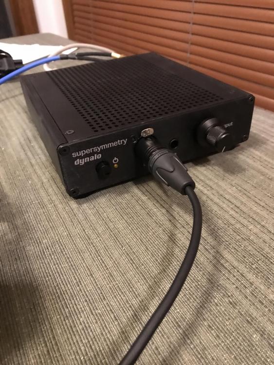
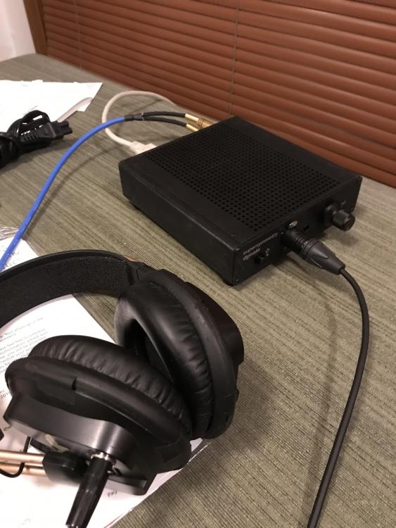
Listening to nopants amp tonight (Curve - Doppleganger). Sounds awesome! iphone -> Vox w/no eq -> amp -> modded T50RPs. I'm really enjoying this tonight... Pics remind me I need to clean it as I've been abusing it in the basement for a bit. Also don't have the heatsinks installed yet. It seems the top, etc. don't get as hot... I'll have to shoot some temps with my IR gun tomorrow. I know @johnwmclean doesn't run heatsinks on his and felt it ran just as cool.
-
Yep. The new mini looks great.
-
The Lemo stuff always looked kind of long for a headphone connector on the cups, but I've never used them. Also very expensive, think I saw one that was $110 ea. Which fake China stuff have you used? I'll have to measure and see what I can get away with diameter-wise. I was also looking at SMC connectors, but they might actually be too small in diameter.
-
Why not? You might have to recheck the offset. If you feel this is bright, I would go with JFETs instead as I don’t think you will gain anything with the 3381s. Sent from my iPhone using Tapatalk
-
There are a couple in posts 814/815 from 12/10/2016 Sent from my iPhone using Tapatalk
-
Well, the “build quality”* looks great, what could go wrong? * otherwise known as the enclosure... Sent from my iPhone using Tapatalk
-
I used knobs from eBay seller AudioGD and liked them quite a bit, finding them to be nicely finished. 25mm is about as big as you can go on these; might get away with 30mm. Sent from my iPhone using Tapatalk
-
Thanks Nate. I ll consider those, but a bit pricey since i would also need the plugs...
-
Don't adjust the pots with the servo 0R jumpers in; normally this is done without. And yes, those look like good results. What does the other channel look like?
-
Yep, when I tried the onboard regs, I had problems getting the jumpers to bridge properly as well. They do go to ground, and anything going to ground on the 3oz boards was a problem, particularly if you were trying to use a sane tip size for the application. The tab on O23 looks a bit light on solder... looks like you used hot air and paste on most of the SMD?


