Pars
-
Posts
8,491 -
Joined
-
Last visited
-
Days Won
7
Content Type
Profiles
Forums
Events
Everything posted by Pars
-
Agreed. I ventured over to ASR the other day, and happened upon a thread that Amir was measuring a couple of Stax amps. Kevin wandered by and explained to him why his standard 100K load wasn't going to cut it here. After much handwaving, Amir declared that he shouldn't have to read (and understand) an amp schematic in order to properly measure one. Somehow he managed to not blow up his AP or whatever it is he is using to do his measurements. Thread closed. D-bag indeed!
-
Are Mouser or IXYS going to do anything about it, or have they been told?
-
Happy Birthday Jeff!!
-
Barrier strips: For the carbon I'm building, I have 4 pairs of primary wires (2 transformers). I was thinking about using some barrier strip(s) to combine the primary wiring to the IEC (for the time being). Any particular ones any of you use and like for this type of application? Covered might be nice as well, since it will have live AC on it. I was looking at some at Mouser, but there is considerable choice, so thought I'd ask.
-
^ Agreed... great actor RIP Christopher Plummer
-
OK. Actually, I had looked at them but was having trouble discerning which OV cat was most applicable since they all looked to be more building power related. – Overvoltage categoriesThe standard has divided the possible overvoltages into four categories. The three categories which relate to connectors are shortly described below: Overvoltage category I Equipment (e.g. connectors) intended for the use in applications or parts of installations in which no overvoltage can occur.Examples are low voltage equipments. Overvoltage category II Equipment (e.g. connectors) intended for the use in installations or parts of it, in which lightning overvoltages do not need to be considered, however switching overvoltages generated by the equipment. Examples are household appliances. Overvoltage category III Equipment (e.g. connectors) intended for the use in installations or parts of it in which lightning overvoltages do not need to be considered, however switching overvoltages generated by the equipment, and for cases where the reliability and the availability of the equipment (e.g. connectors) or its dependent circuits are subject to special requirements. Examples are protecting means, switches and sockets. From this, it would seem that category II is the most applicable. Pollution degrees of 1 or 2 would also be applicable since the amp shouldn't have any condensation present, even briefly (degree 2) so no conductive pollution should be expected (briefly is allowed for degree 2). So the ii/2 spec would be applicable, but for safety, the iii/2 rating would be what I would look at.
-
Thanks. Not quite sure how to apply that here though, as the datasheets are inconsistent. I suppose the 651-1729047 should be OK, though Mouser calls these a 250V part. The 651-1800090 is shown as a 400V part. I need to order the CPC1117N and resistors for the soft start anyway (universal PSU; not for the Carbon), so I guess I'll get the 651-1800090 and use them.
-
It is the Hirose series which will fit, and are 500Vac rated (https://www.hirose.com/en/product/p/CL0676-0019-7-35). Just to note, the Phoenix connectors shown on the BOM I had, as well as many of the BOMs in this thread (651-1729047) are only rated for 250V (data sheet claims 400V)? I haven't looked into the III/2 and II/2 spec to see what that means. I thinking of replacing with these, which are 400V: 651-1800090, though it uses the same III/2 rating. These do say 400V nominal however. I am using Kapton tape under these, and would guess that many have built theirs using the 651-1729047 parts?

-

TKD 4CP-601 & 4CP-2500 4-gang volume pot and PCB GB
Pars replied to mwl168's topic in Do It Yourself
I don't have any spare boards left, and I thought I had posted the gerbers in this thread, but I guess I hadn't. Here are the gerber files for the 2-pot (CP601/CP2500) and 3-pot (CP601/CP2500/Alps RK27) boards. Some place such as seeedstudio.com can run these for pretty cheap. Just give them the entire .zip file. TKD 4CP 2 pot final.zip TKD 4CP 3 pot final.zip -
Can anyone offer advice on how to replace the pot in my KGSSHV?
Pars replied to loz_the_guru's topic in Do It Yourself
The pot you currently have in the amp is an Alpha (or Sung Huei) RK2142G (datasheet attached). The 4th pin is a loudness tap. So basically, transfer the existing wires straight across to the TKD replacement. Watch the heat on this; try to make good mechanical connections and don't linger with the soldering iron. Looking at your first pic (the TKD), the pins in order from left to right would be ground, wiper, and input, or 1, 2 and 3 corresponding to the attached RK2142G datasheet. The Alpha pots aren't bad at all, particularly for the price, but not in the same class as the TKD. BTW, where did you obtain the TKD from? RK2142G.pdf -
Agreed Al. I hadn't realized that Cicely (or Cloris) were that old. RIP to both of them.
-
Anyone have any idea what this damping material is? It is what was used by GNSC for their mods to my Resolution Audio Opus 21. It kinda looks like dynamat and is 3.4mm thick but doesn't feel like dynamat (or smell asphalt like). Is it Paxmate?
-
So did Catherine Wheel...
-
RIP Hank...
-
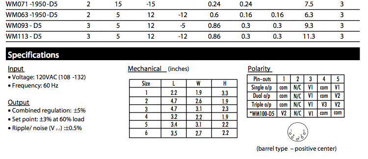
The DPS or required PSU pinout would match the Elpac wallwart these used to come with. V1 is V+, V2 is V-. From the datasheet:
-
Happy Birthday Mike!
-
Thanks for replying. Very clever use of the grommet strips. Once you brought them up, I recall seeing these used for grommet holes. I would have never thought of using them for this purpose. Well, maybe if I had some on hand, a light bulb would have gone on...
-
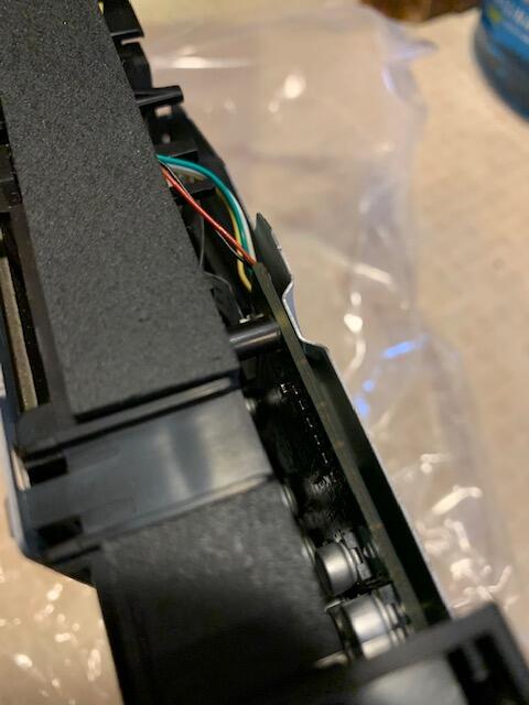
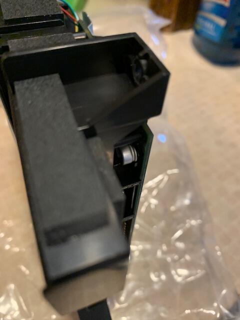
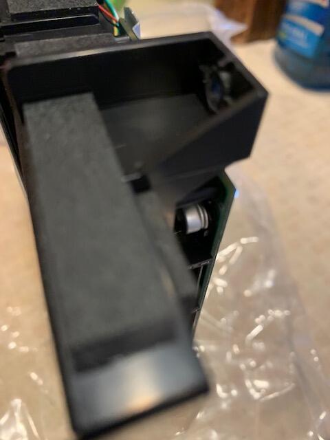
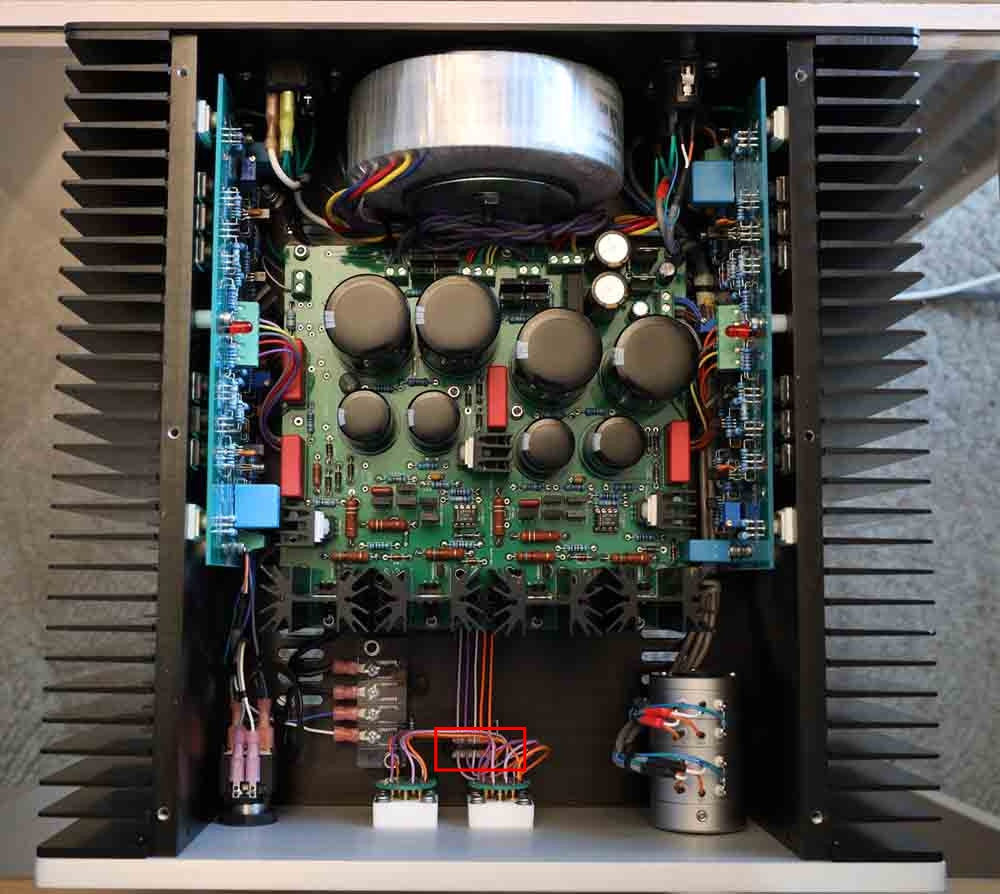
I had looked at this closer awhile back, and noticed what looks like a wire loom or separator down on the floor of the amp by the output jacks, to hold the output lines in order. Is this something that you made, or is commercially available? I did a quick search at Mouser but didn't turn up anything like this. Thanks!
-
Happy Birthday Grahame! And what Steve said
-
RIP Pat DiGiacomo (aka Jocko Homo), passed away Nov. 4th. Good guy, knowledgeable engineer, but came off as being a bit cranky https://www.diyaudio.com/forums/in-memoriam/362564-rip-jocko.html
-
Doing a google search (which I assume you have done ad nauseum), revealed an Audio Karma thread which might be of assistance: https://audiokarma.org/forums/index.php?threads/cd-player-belts.345514/ http://www.kenselectronics.com/lists/belts.htm
-
This project on diyaudio implementing a Muse chip for analog volume control might be of interest to you: https://www.diyaudio.com/forums/swap-meet/322983-muses-volume.html
-
I've been watching it as well, though I'm not caught up (S1E4 was the last I watched). I'm enjoying it, and would recommend.
-
You mean the 3 parts (XLRs, RCAs and switch)? It seems to though I haven't measured or done any sort of mock up. I think there will probably be enough slop possible in assembly to get them to match, but I'll play around with it. The switch is an NKK m2042xxxxx, and the Neutriks are NC3FAV2. I tied the two chassis gnd connections from the Neutriks together with a pad in the middle, and did the same with the pin 1s. Then put two pads in connected to the board gnd plane. I'll probably add another pad for chassis ground to give the most flexibility. On my Pass Aleph P, the XLR grounds both go to board ground. Same on Kerry's SS Mini. I haven't had any hum problems whatsoever on my stuff, but everyone has different issues potentially. Thanks for getting me thinking about this shit though I also used a drawing of the Cardas GRFA DBL PRT that someone had provided on a diya thread you were participating in to draw up that part in Eagle as well, in case I wanted to go that route.