Pars
-
Posts
8,516 -
Joined
-
Last visited
-
Days Won
7
Content Type
Profiles
Forums
Events
Everything posted by Pars
-
Hope you had a good one!
-
Particularly when it is on... <<<shudder>>>
-
It seems odd that if, in Mikhail's mind, there are issues needing resolution before he can ship Elephas' amps, that he would be actively trying to contact Elephas. Sounds like he is ignoring Elephas' attempts at contacting him. Something doesn't add up...
-
I very well could be wrong, but I wasn't aware that the user could take an ad down at audiogon? I thought they just automatically aged and disappeared when they had been up a certain number of days?
-
Try this (attachment)

-
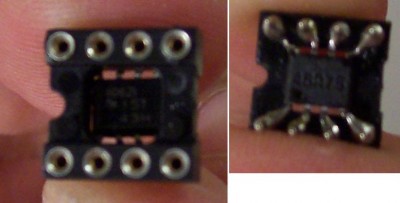
For SOIC to DIP adapters, I saw a neat technique on diyhifi of putting the chip on the bottom of a DIP-8 socket... gets the chip 1-2mm closer to the the pins and gives you room on top for stuff like the rail to rail cap, etc. DIYHiFi.org • View topic - KC7 Look for carlosfm's post (about the 3rd one or so), with pics. His bypassing techniques were what i was going to use for a start if I went to the THS4031/2 chips (100uf Pana FM right on the power pins to ground, etc.).
-
From what I've been told, you don't want the painted anything from Par Metals... go anodized entire case. Then again, I'm an observer here, so...
-
Ahh, I think I got confused Thought he was contrasting some other failures... upon rereading I guess not.
-
I found this post in the HF thread to be a bit more unsettling: That seems to be alot to gut for parts... The one in Chicago may have been Absorbine's Zana that wouldn't fire up (Feb. meet)?
-
I think what KG is alluding to is that the perception created by Ray's fanboys makes Mikhail feel as though he needs to act; in this case by coming out with innumerable models which drives inventory ($$$ components) as well as loss of focus on existing problems (customer amps in for repair or builds).
-
Happy Birthday! Hope you are healing up OK (leg was it?).
-

Relative Importance of Power Cable/Power Conditioner?
Pars replied to barmar46's topic in Audio Accessories
I'll take some of the drugs this guy is on x24. Source is way more important. Buy a good CDP with good DACs in it and you don't have to mess with SPDIF. Some people like systems without a preamp... Reks was doing that for quite awhile. Now he has a preamp. What Nate showed you (looks like an audioasylum Bob Crump cord) is all you need for power cords (or Volex 17604 IIRC). -
You left the 2 * pi out of your formula, but must have used in in your calculation. I would think this should be sufficient. On my recent coupling cap experiment in my preamp, I had used a 1uf on the output, given the 1M resistor to ground. Of course I forgot to account for the amp input impedance in parallel (10k), so the 1uf gave me ~14Hz... definite rolloff that I could hear. Went back to an 8uf cap as the stock one had been. No rolloff that I can detect by ear now, and RMAA looks much better.
-
We like mutated crapped threads here apparently... we'll keep em straight
-
Thanks for the insight on the THS4031 vs. 4032 Filburt. Had I not gone to a discrete output stage, those were where I was going next, and my player's stock I/V was setup to use duals. Of course I knew if I went to these, I would have to do alot of rework/bypassing to the stock stage to begin with. Regarding the NPO ceramics, are COG available in this size? I forget how big they get (0.1uf? or 0.01uf?) but it would be interesting to see if you noted similar problems with these.
-
IIRC the enclosure that I got last December directly from Context ran ~$45 shipped. That was a 6008 I think.
-
How about a Context Engineering 6016? Split Body Enclosures available from Context Engineering I like these better than the Hammonds.
-
If you don't mind a split bobbin, Allied has these: Hammond Manufacturing - 186D56 - Allied Electronics 56Vct, 30VA They also have some 6VA Hammond and Triad.
-
sometimes their (Neutrik) strain reliefs have a piece or section you can remove for thicker cable. Its usually not clear at all in their instructions... what particular connector?
-
I see where you're coming from Marc. I don't think the price of most of the hi end amps such as SPs, RSA B52s, etc. has anything to do with cost and more to do with perception of what the market will bear. People will pay it, so there ya go.
-
Nate, I hadn't noticed your new avatar... nice, Dad!
-
Looks a little toasty where the FET had been. And not just any electros, but these look like BG VKs. Note also the VCaps, etc. Lots of hi $$ parts in here, with really poor execution. Which resistors were you referring to earlier that were supposed to be the non-inductive WW? The long brown ones? For what is being paid, no Mills MRA-12s or something else decent?
-
Not much to soldering... just heat both parts up and apply solder. When you do it right, the solder will just kinda suck into the joint and you can see it. I think alot of people make it into a bigger deal than it really is. Just do it That is some weird heatshrink! I have one of the crappy Harbor Freight heatguns, and like Nate, I would be afraid to use the high setting on it. I actually unsoldered a connection to a pot or something on the low setting. I'd bitch to Markertek about that shrink.
-
Watched it for the first time Thursday and liked it. I thought the acting was a bit meh at times, but I did enjoy it and will watch it again. Still spoiled by The Shield as my favorite show though...
-
What is this thing? Where's the DAC? Or is it the dip-8 (TDA1543/1545?). Passive I/V with a couple of Rikens is it? And are those two transformers behind the red BGs for the output stage?