Pars
-
Posts
8,503 -
Joined
-
Last visited
-
Days Won
7
Content Type
Profiles
Forums
Events
Everything posted by Pars
-
Anyone got any 2K or 2.2K 1/4W PRPs they could sell? Discovered I have none small enough for the dynafet (have RN60Ds).I'd take 10-12 or so if you can spare them.
-
Thanks Scott! I replaced R17/18 with 3.3K resistors (and socketed them this time so easier play time). Min. bias of 160mV (80mA), max of over 500mV (250mA). Dug thru my parts and I don't have any 2.2K resistors . I do have some R60s but I'm not going to try to cram those in. I was going to replace the 5K R19/20 (the alternate feedback point) and see what effect that had. Then drop R62 from 3.3K to maybe 1K, per your findings. So if anyone has any 2.2K PRPs... If I have to order them, should I get 2K or 2.2K? The latter is probably more useful overall. I put the Fluke in series with the positive voltage feed. At 150mA bias, the board is drawing ~375mA. Heatsinks on the sigma are pretty cool, so I don't think running a stereo set biased at 150mA is going to be a problem. DC offset looks good, and pretty stable at 3mV. I have not put the servo opamp in yet, and have not tried to adjust offset with the pots which are both set to 500 ohms total for the resistor/pot combo.
-
Sorry to hear about the fingernail Nate, and yes, it made me wince as well. Hopefully feeling better now. Hope you feel better Matt! Ken, I know the feeling of having to lay there. I had a inferior vena cava filter put in a couple of years ago before my hip surgery and had to lay there motionless for 4 hours afterwards. Having it taken out was more uncomfortable, but at least I didn't have to go through the motionless crap.
-
Also, the gate voltage is at 2.99 Vdc currently (at the 450mV/225mA bias). I may be missing something, but don't the gates set the bias (or apply it I guess would be more accurate)? Since these are in parallel and driven by the corresponding diamond buffers, wouldn't the Vbe multiplier settings be pretty much independent of how may output devices you are actually running?
-
I replaced R17/18 with 10K resistors and put the 20K pot back in. Down to 450mV. Scott: from one of your previous posts (a year ago or so, probably before the boards were even ordered) I may drop R17/R18 to 2.2K and see what happens. And also try to decrease the pot size further. I know I have some 2K, but will wait to do this until I can get it well below 150mA. I figured 150mA would be my target, but I want to have adjustment range on either side of that. I assume that if I start mucking with the pot size and series resistor (R62) before I am able to get it down that far that I will be cruising on fail At 150mA, would I be looking at ~300mA per channel for power draw (4 devices or 2 pairs per board), and should a single Sigma22 handle this OK? Since I already have this case, a single sigma22 is mandatory (no room for a second one).
-
Yes, you told me to leave these at 20K (R17 and R18), so I did. Like I said, I have 4 devices (2 pair) in. R19 and R20 (alternate feedback point) are 5K. Either you or digger told me that was what you used when I asked if it was 2K or 5K.I sent you a pm also Marc.
-
Update: I tried adjusting VR3... I can go up, but not down. I replaced VR3 with 1 100K pot. Resistance at max is ~34K (it is in parallel with R19 + R20 or 10K total), including R62 of 3.3K. Voltage across the 2 ohm resistors dropped to ~700mV, so 350mA bias current. I measured DC offset and it was around 2mV, and seemed stable (for as long as i dared to leave the amp on, or 30 secs.). What effect does increasing or decreasing R17 and R18 (currently 20K) have? Should I drop these to 10K or go up?
-
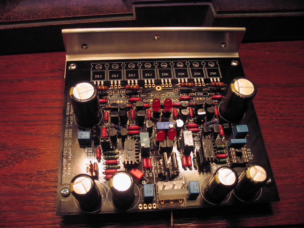
Well, went ahead and put the output devices (2 pairs) in and fired it up. Seems to work. Had 2 DMMs, one on each J/K source resistors. Started out at 1.05Vdc (500mA), and was dropping. I only left it on for ~30 secs (2 x) and they had dropped into the 800mV range, but that is still 400+ mA. Did not try adjusting VR3 yet, as this seems to be too high. VR3 was set to max resistance, but I will verify this. It is bolted to a heatsink (hifi2000 pesante dissipante). The dynahi angle brackets I have do not go completely under the TO-220 tab (1x1" angle). 1x1.25" would be better. Thoughts?
-
double post
-
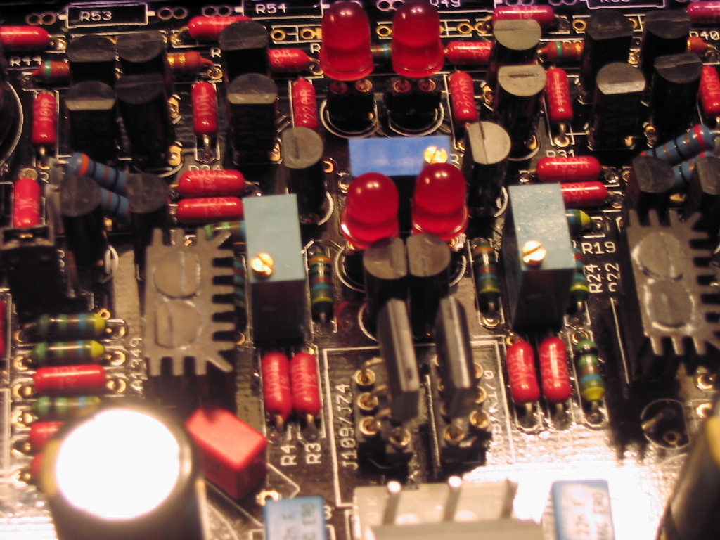
The TO92 dual heatsinks came from Marc (from a diyaudio group buy I believe). No, it was pretty easy to insert them with the Arctic Silver... just messy. Marc: do you think I would be better off to just put all the FETs in? As for the "Vbe multiplier" (have to look that up), I just need to ensure that i have adequate adjustment range? Per our conversations, I have 20K R17/18, a 3.3K R62, and a 20K pot currently. Oh, BTW, do you have any extra FETs?
-
I like using Amb's adjustment procedure. Used it on the Dynahi and it worked well. http://www.head-fi.org/forum/thread/165788/dynahi-dc-offset-adjustment#post_1960704
-
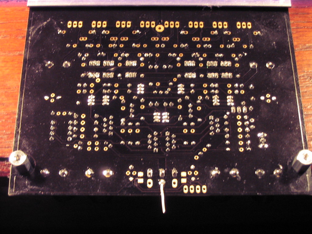
Making progress. One board done other than the output devices, the other almost at this point as well. Fire in the hole this week sometime Will only be 1/2 populated on the outputs. Will probably begin testing with a single pair.

-
Also seems to lose track of some read items. My setting are set for Show me all content that I have not read... Some items that I have read reappear on subsequent visits.
-
It appears that what it is doing is putting up individual instances of the thread for each unread message that there is in the thread. If there are 2, you get the thread appearing twice, etc. At least that is what looks to be happening.
-
Looks nice Kerry. What layout software are you using? My only comments would relate to pad sizing, particularly for the TO220 devices. I much prefer the larger elongated pads for these as they seem to help regarding rework if needed.
-
HTFU...
-
probably "8" followed by ")"?
-
Yeah, I like the screw mount heatsinks a lot better than the pin mount ones. I would imagine getting those out of a tight space would be teh suck.
-
Yep, great news Reks! And good luck on the position Dan!
-
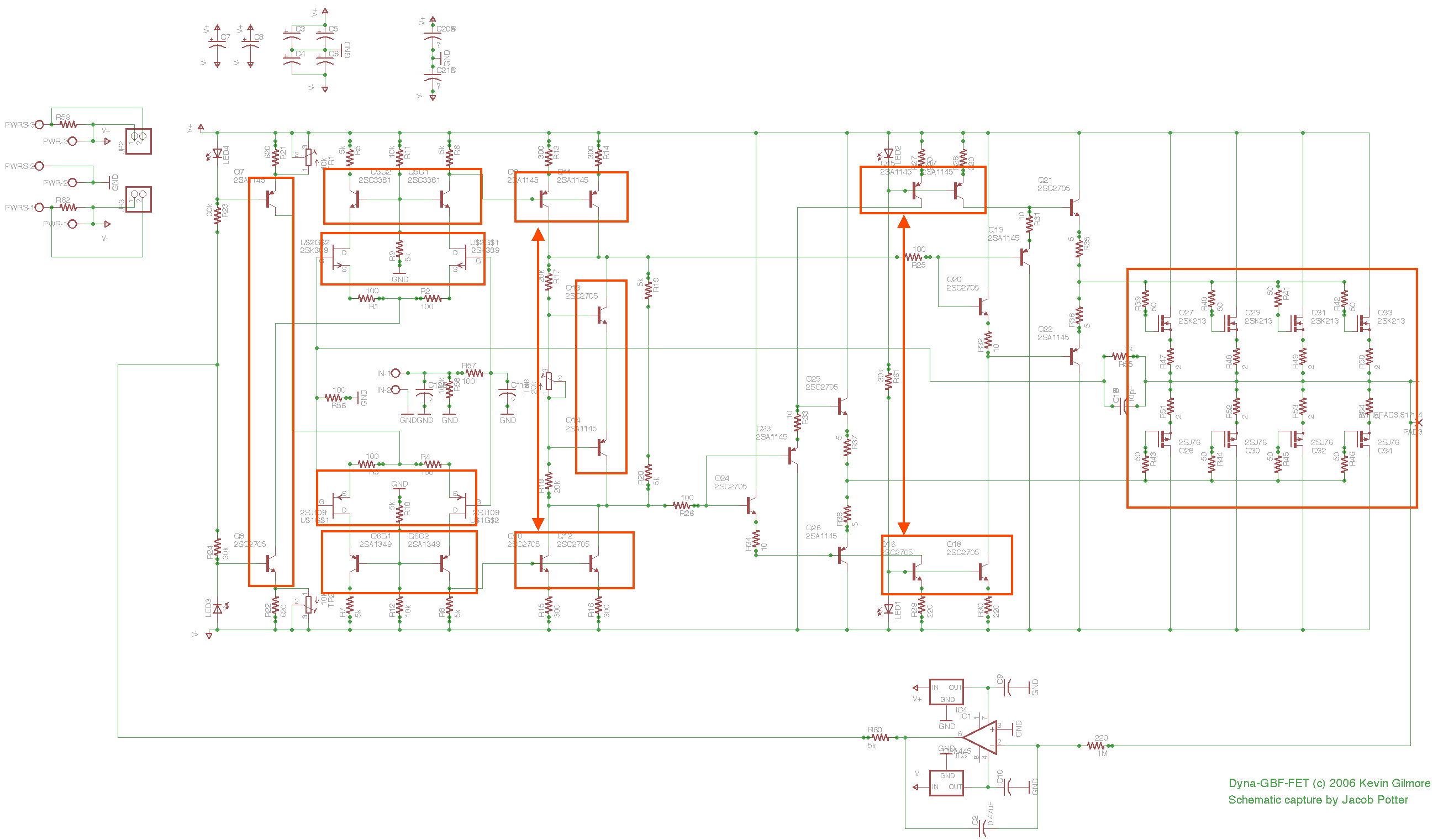
Did some reading on headwize, so the max resistance sets the lowest biasing; decreasing this increases the bias current... DOH OK, got my 50 each 'O' A1145/C2705s from Mouser and did some matching last nite (oh fun ). They were pretty consistent but not matching well between NPN/PNPs. The NPNs ran from about 95 to 114 hfe, while the PNPs were from 118 to 155, with all but 6 at 140+. Device classification range is from 80 to 160 for the 'O' devices. I do have some 'Y' devices with hfes in the 150 range for the NPNs (not enough, but some), so I may use this approach for anything deemed critical. Speaking of which, are there any areas where the devices should be matched well? Output FETs obviously, and the 2SK/2SJ parts should be as well. I mocked this up on the schematic indicating areas where matching might be important. Any comments?
-
Happy Birthday Mike! Trip to FFF today? Have a great one!
-
Sorry about the snow guys... its currently -6° F here, light wind so not too bad. At least the sun is out
-
I immediately thought that M-80s might be fun...
-
Didn't read your welcome pm, did you?
-
I currently have my setting on "Show me all content I haven't read". When I do a View New Content, I get the same thread appearing more than once. I'm up to 2 pages now, but probably the same 12-15 threads in it...