Pars
-
Posts
8,503 -
Joined
-
Last visited
-
Days Won
7
Content Type
Profiles
Forums
Events
Everything posted by Pars
-
I'm building a couple of the UGS Muse preamps from the french site homecinema.fr / diyaudio. The only part done on both of the is the processor boards, and yes, it was easy to flash. These do use the 72323 chips (which I haven't bought yet).
-
Any experience with the Muses volume controller IC in place of clacking relays?
-
Any of you watching the new series on Apple TV, Slow Horses? Gary Oldman stars, about a slow witted bunch of MI5 agents in Britain. Pretty good. I think the first 3 episodes are out now. We finished watching the Night Manager and enjoyed that. Though we (my wife) loves Hugh Laurie (House).
-
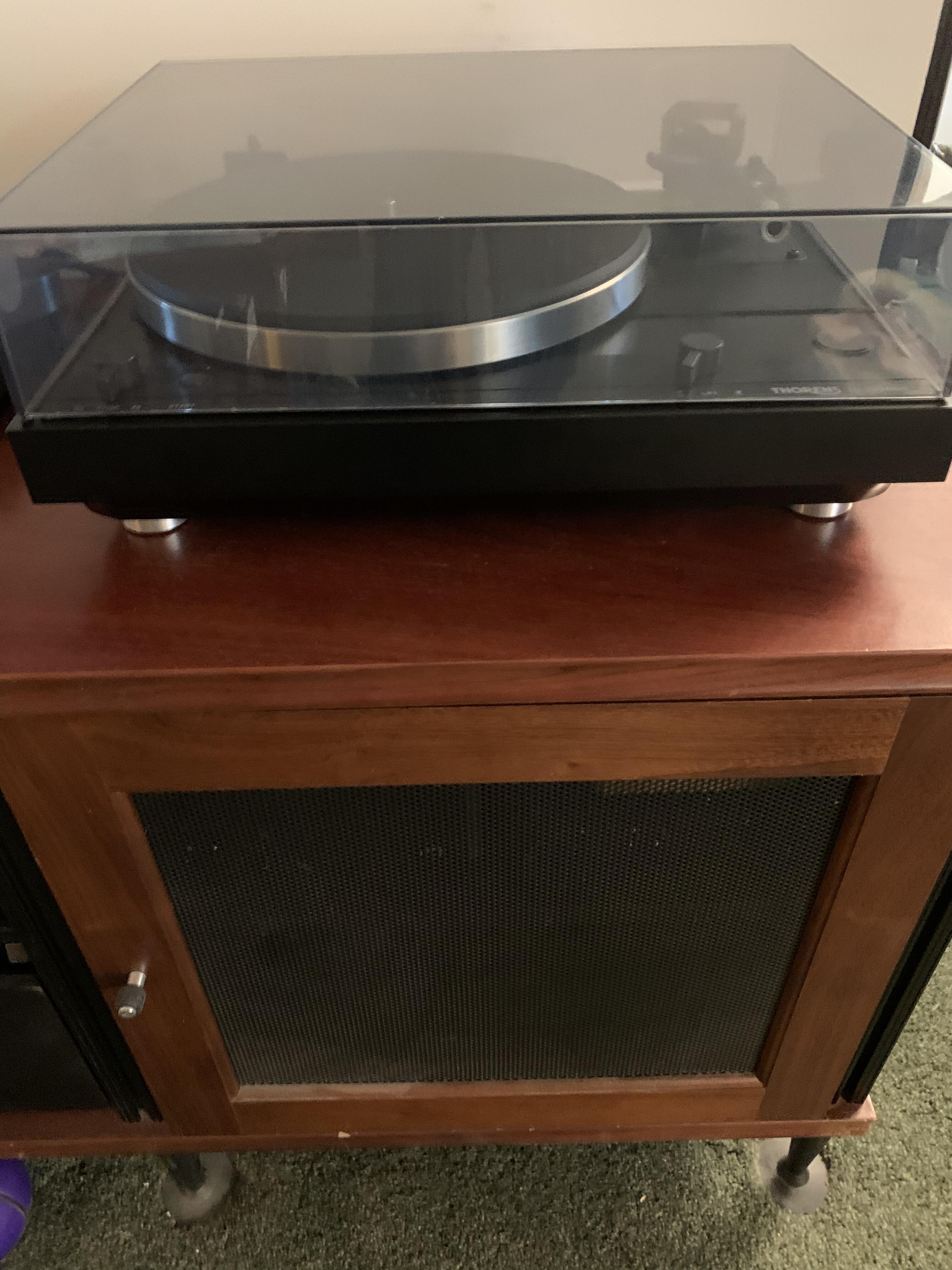
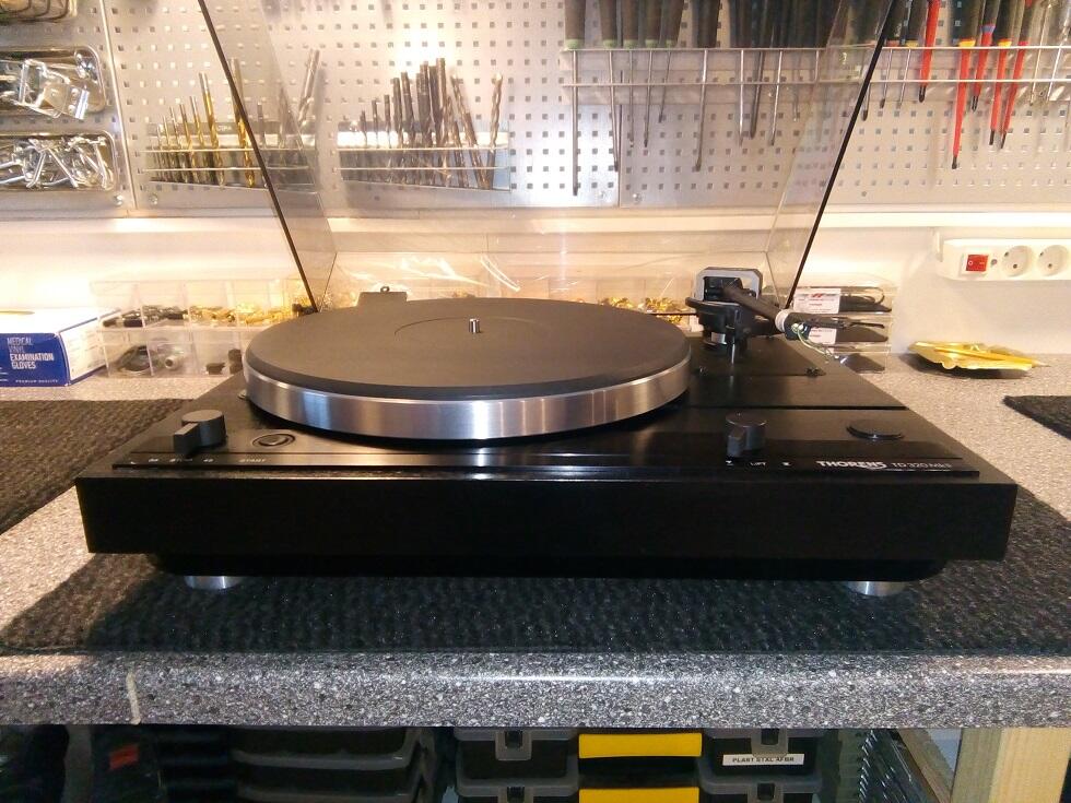
Bought a restored Thorens TD320 Mk ii from a shop in Denmark. I liked my original Mk i, but wanted the better arm. I'm installing a Grace F9e with SS stylus on it. Might not be the best match, but will see.

-
Happy Birthday Tyler! Ditto on a safe one!
-

and now for something completely different part 3
Pars replied to kevin gilmore's topic in Do It Yourself
I actually got them from ebay. I think Kevin had posted a link in one of the threads, probably the Dynalo thread. Ebay isn't showing me who or what these are (only goes back to 2020 purchases). I'll keep looking. EDIT: it was something like these: https://www.ebay.com/itm/254636284745?hash=item3b49815b49:g:CGIAAOSw8s1gnfky -
Looks nice. Interesting chassis! I've been using the same Wago connectors as well (2- and 3-way). They're pretty slick and apparently are good up to 450V.
-
^ Thanks! I figured it might be something from Mill-Max, but hard to go thru all their stuff.
-
Nice! A couple of questions: How do you guys cut the angle brackets so nice and clean? What are those test point pins used in the boards? Do you have a part number/source? Thanks!
-
Wow, no shit. Hard to believe. RIP Taylor.
-
Sorry for your losses Bryan. My condolences to you and your family.
-
What a fucking douchebag. They probably have (a bunch of) video on him. Persecuted? How about being held accountable for your actions?
-
^ Agreed. Watched the 1st two episodes tonight.
-
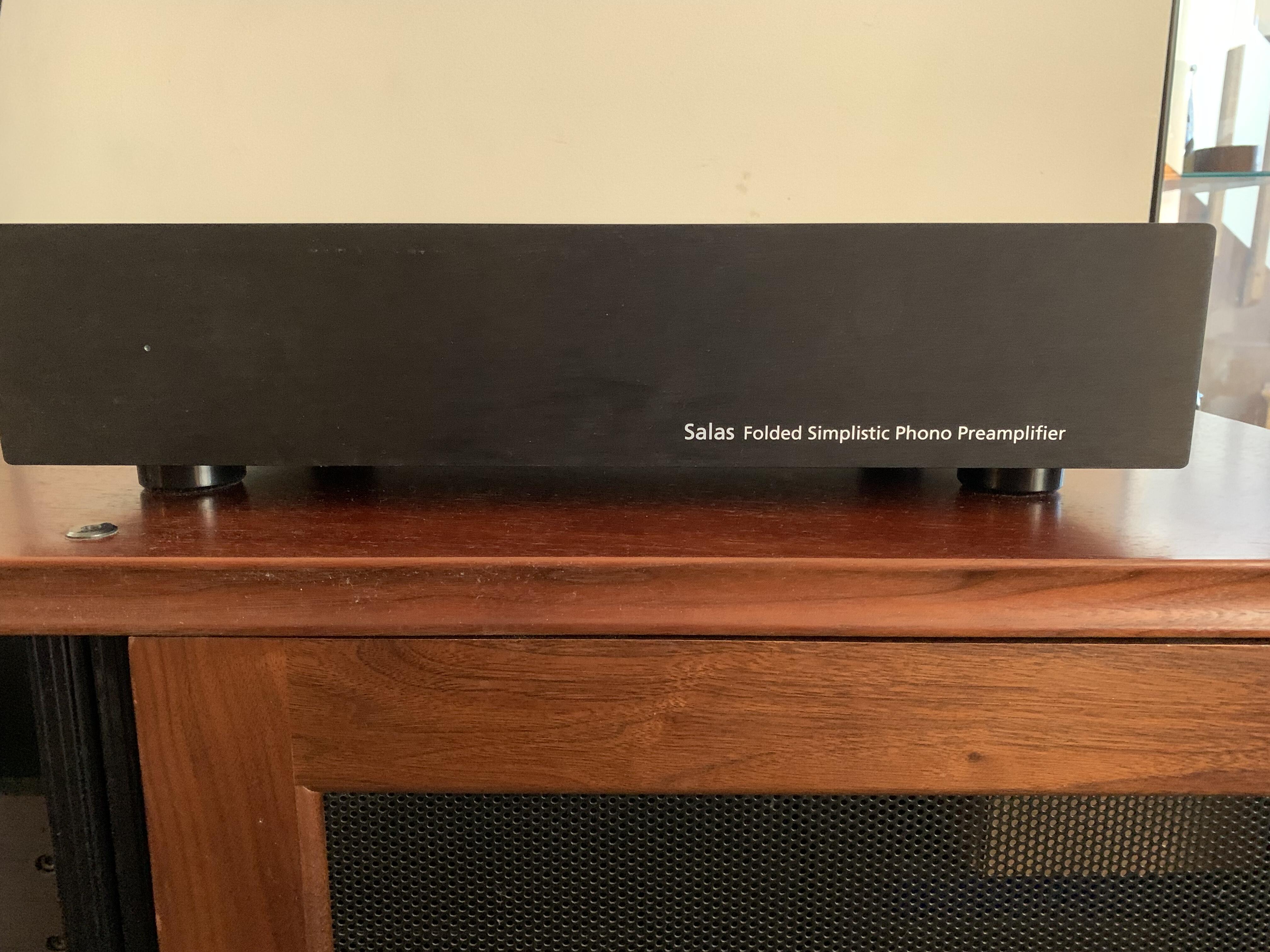
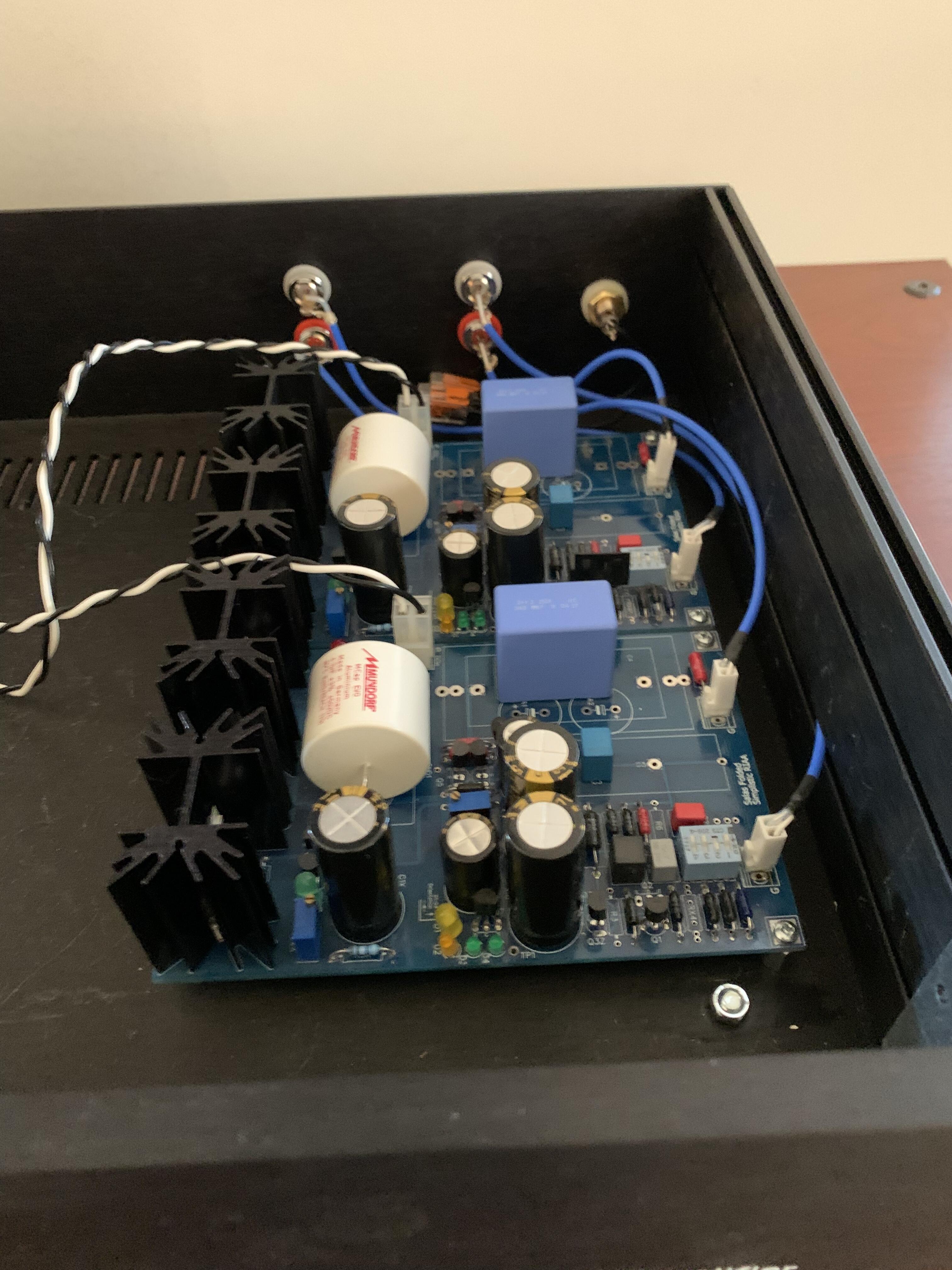
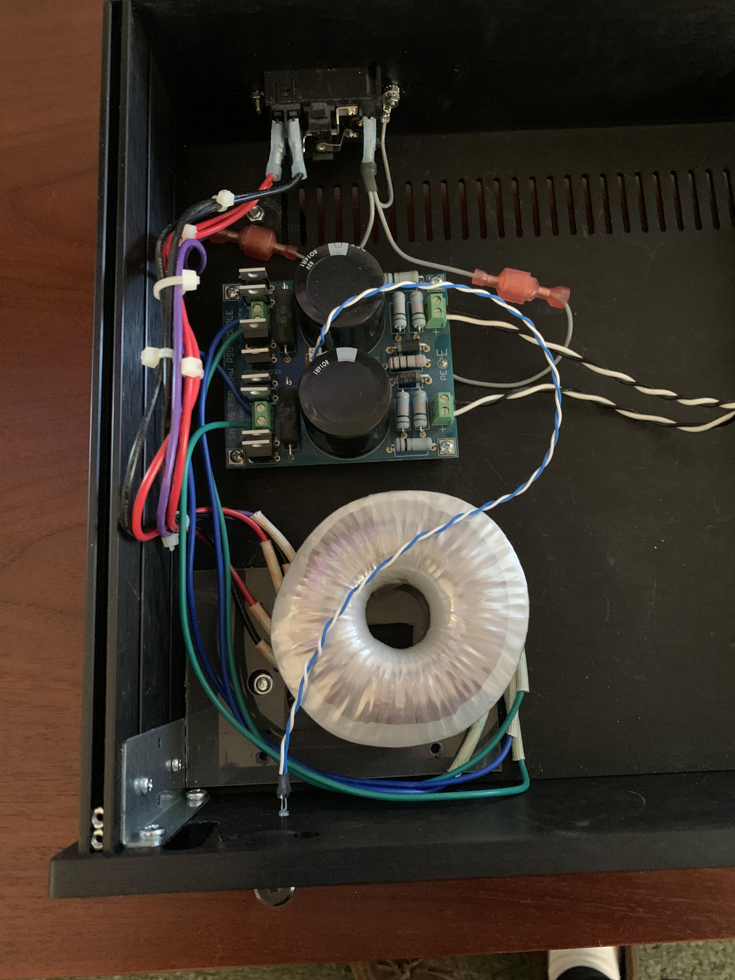
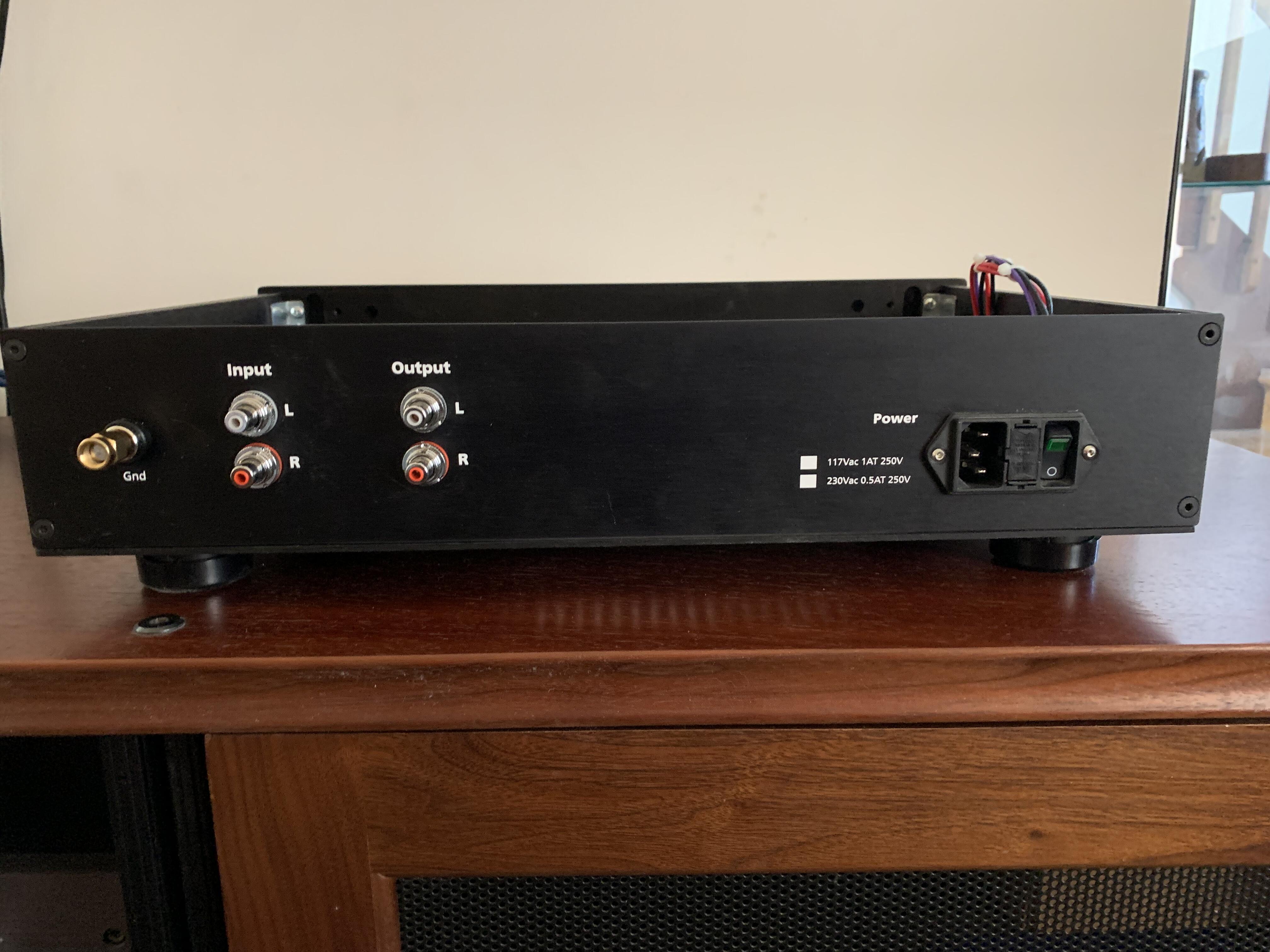
Nearly finished casing my Salas phono stage. Need to mount the transformer and raw PSU. I may use a vandal switch on the front, but some type of momentary switch board or at a minimum, a voltage select board will be going in as well. Also need to shorten transformer leads, and clean up wiring. Runs dead quiet in my system; no noise evident when turned up all the way at tweeters or via headphones. I've got the Antek steel transformer cover and a set of Mundorf Supreme caps, though the kids all seem to be going for the Clarity Caps these days. It sounds good with the BC polyprop and MKP1837 I have in there now. This is setup for MM at 42dB gain. Loading switchable to several different values via dip switches. Set at ~34K right now for the Ortofon 2M Bronze I was using (a bright cartridge IMO).
-
Happy Birthday Al! I hope the drive is good and you have a great one!
-
R1 is 4.7K (Soren said 4.5K in his text). Regarding the low voltage test, for the GRHV, the gain is calculated similarly to the GRLV? i.e., ((Ra / Rb) + 1) * Vref, so for this one set for 400V, it would be (((390K + 390K) / 20K) + 1) * 10, or 40 * 10? If I did something like parallel one of the 390K with 1K, I would get ~205V. Using an Antek AS-3T325, the GRHV should regulate at about 75Vac input (325/115 turns ratio)? Just making sure I'm understanding the concept. Or would you go even lower for this test? James recommended ~50V output for this. EDIT: If I parallel 100K across the 2x390K that would give me about 55V output. I'll probably do that instead. goldenreferencehvsic.PDF
-
OK, ran thru this on both boards: Initial check: The CCS's Use a lab supply at some ~15-20V, through a DMM at mA: put the (+) at the drain (middle leg) of the 10m90, and the (-) at the bottom of the CSS where R2(100) and R1(4k5) meets ...you should get ~2mA ....if you see much more, try replace the DN2540. Do the same at the other CSS: (+) to drain (middle leg) at the 10m90, and (-) at the bottom (pin 6 at the voltage reference) ...you should get ~1.3mA ...if not the 10m90 is probably damaged. Check the current limiting CSS you added (your drawing) the same way (Kevin suggested 50mA for this) For the first test, I was getting 1.6-1.7mA for both boards. 2nd test I was getting -1.3mA with the red lead on the 10m90 and black on lt1021 pin 6. I guess I will assume everything good so far...
-
Thanks James (and John). I was going to go thru the checks that soren laid out in the circlotron thread (and I copied his post earlier in this thread), and then power them up on a variac, unloaded. It might have been a 16K resistor that Kevin had mentioned, but I never bought any load resistors for doing this. Unfortunately my variac doesn't have an ammeter in it, but I'll just take it slow. I also don't have a dim bulb tester, but if needed, might build one.
-
About to (finally) begin testing the pair of GRHVs (and a Carbon) I built. Do I need any sort of load for testing the power supplies? I seem to recall seeing Kevin recommend a 16ohm x W load resistor.
-
No shit. Seems mighty Christian of him..."Nuke em all til they glow..."
-
and now for something completely different part 3
Pars replied to kevin gilmore's topic in Do It Yourself
Here they are. THAT340-J109-K389-JFET.zip -
and now for something completely different part 3
Pars replied to kevin gilmore's topic in Do It Yourself
Kevin, The pinout of the bipolars is not compatible with the 2sj109/2sk389. I did boards for those and can supply the gerbers. They should also be in one of the dynalo, etc. group buys that Steve ran (sbeylo) some time ago. -
Happy Birthday Fitz!
-
Happy Birthday Nate!!