-
Posts
8,473 -
Joined
-
Last visited
-
Days Won
7
Content Type
Profiles
Forums
Events
Everything posted by Pars
-

and now for something completely different part 3
Pars replied to kevin gilmore's topic in Do It Yourself
Are you taking the + signal connection after the relay on the protector board? If you are taking it from the channel boards or before the relay, then I would expect a thump. Taken from the point your headphone jack is wired, it shouldn't thump I wouldn't think. -
Good to hear on the caps insanity. Did you use the Kemets? I think those are pretty good, at least I haven't heard of anyone having problems with them though I don't know how long they have been in use and don't recall the history of that brand. I see they are owned by Yageo now. Desoldering those shouldn't have been a big deal. You just need a big enough tip and use a good solder sucker such as an Edsyn or an Engineer. I use a 3.2mm chisel tip on my Hakko 936 iron, and turn the temp up >700F for larger connections such as this. The boards these days are pretty good, particularly 2 layer boards, in terms of reworkability without lifting traces.
-
Those would be fine. Some drop down to the 470uf in that cap as well, particularly if you are trying to get this in a 2U chassis. When I built the one I did for a French user, the 680uf were no longer stocked at mouser in the US. Some discussion in the GRHV thread here:
-
Happy Birthday!!
-
Happy belated Birthday!!
-
Looks like you have to buy 250 of them though...
-
Not sure where you are at, but Octopart shows this: https://octopart.com/search?q=FJPF2145¤cy=USD&specs=0
-
For the 335, you'll need dual (2x335 as shown). Are you planning on using a GRLV or the onboard +/-15V supply? For a GRLV, you can use either (depending on version of the GRLV). If your board has space for 3 bridges, you can use either a center tapped transformer, or dual secondaries. It it is only 2, then you need the dual 2x15V secondaries. You are pretty much always safe with dual secondaries vs. center tapped.
-
That looks like the correct schematic. The boards look fine I think, assuming that the one on the right, which is chopped off in the photo, is for -400V. Given the age of these boards, you might scan completely thru the thread to ensure there were no board errors found. I seem to recall one, which did not affect the boards that I used. Here is a schematic for the GRHV. The 900 board you have listed above is for something else (Megatron or something). Also note there is a separate GRHV thread now as well. goldenreferencehvsic.PDF
-
These guys have anything that you think might work? https://amscope.com/
-
Happy Birthday! Have a great one!
-
-
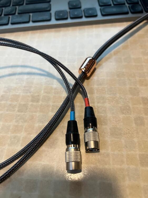
I liked the sleeving I bought from a place called Titan Rig. Can't recall where I found them recommended, but it is softer than any of the parachute cord, etc. that I have gotten before.
-
Happy Birthday!!
-
Happy Birthday Kerry! Hope the amp business is doing well!
-
Hmm. So it seems pretty clear that it is something on that board. I don't recall where the tubes mount on the KGST? If they are on sockets on each board and mover with the board, then MLA's post above would be something to try as well. I would take the board out and examine all the solder connections, probably reflowing them or at least ones that look suspect. I'm assuming you have a soldering iron, etc. as from a search it looks like you built the amp? Since you are in the EU, I presume this used lead-free (ROHS) solder? Another thing you could do is take a non-conductive wooden or plastic rod or stick and poke around the bad circuit board and see if you find anywhere that effects the hum level. If so, that should narrow down an area where there may be a bad connection.
-
When you were checking the connectors yesterday, did you loosen the screws and reseat each wire? I presume in order to swap channels, you had to disconnect/reconnect them all? I'll be interested to see if it now stays quiet.
-
Someone with more experience in the stat amps should come along with some suggestions. From a general troubleshooting perspective, I presume you have checked the rail voltages and verified that they are correct? I would think they would be as biasing and the balance and offset adjustments would have been difficult or impossible if not. Given its age, I would check connections to ensure they are tight. Don't ignore the IEC ground to chassis connection. I would presume this uses those god awful* phoenix screw down connectors? I would loosen and reconnect all of those as they can loosen over time. * In my opinion. I greatly prefer pluggable connectors such as Molex, Amp, etc.


