-
Posts
1,376 -
Joined
-
Last visited
-
Days Won
1
Content Type
Profiles
Forums
Events
Everything posted by mwl168
-
This may be stating something obvious. The readings between L+/L- and R+/R- are balance. The offset is between either of the output phases to ground. Adjust the balance and get it close to 0 first then adjust the offset. The two adjustments are controlled by two separate trim pots on each channel. You will likely need to go back and forth between the two adjustments to get both to 0. Also these adjustments need to be done without the servo activated.
-
Yes, the cover has cutouts for air circulation on both the top and the sides. I am surprised at how much the heatsinks temperature rises with the cover on.
-
An update on the heatsinks temperature. I put the cover on my temporary chassis today and after two hours the heatsinks went from slightly warm to the touch to hot to the touch. I can rest my hands on the heatsinks without getting burned but they definitely feel uncomfortably hot after a few seconds. Also, the offset shot up to about 30V. The room temperature was about 65F. Both the 2SC4686a and 10m90s are rated to 150F and I've read comments that if you can put your hand on the heatsinks for more than 5 seconds then it's probably fine. So I am a bit concerned but not worried ) My thought is that the heatsinks I use are fine if they will be exposed to open air. I would probably use bigger ones if just for the peace of mind if they will be enclosed inside the case. I would love to hear the thoughts and advice of those that are more knowledgeable.
-
Yes, that's the one I use. I have not experience any hum nor buzzing and it runs cool. The downside is the size - this thing is HUGE )
-
The Tsar has already spoken but since I just built a 400V KGSSHV using a similar PS (kgsshvpsminifinalstn9360) I can also share my experience. You can also referred to my earlier post #4321 which has the exact value of resistors I used based on availability at Mouser at the time. The formula to calculate the B+ is ((R29 + R5)/R6 + 1) x 10V (V out of the LT1021 voltage reference) and similar for the B- side of course. I also read that you should configure the pre-regulate Zener string to 50V above your desired voltage, in this case, 450V. In my case, I have been getting a very steady +408V/-406V output from my PSU. Hope this helps.
-
Thanks! I see that nopants already answered your question but I can confirm what he said. I am running 120R for the R5/R6 on the amp which should yield about 9mA output current. At this setting and without the chassis cover on (as is in the photo I posted), the heatsinks are only slightly warm to the touch when the ambient temperature was in the 65 F range. This does surprise me a bit as the heatsinks, as you said, are on the small side. Sorry I don't have the device to accurately measure the heatsink temperature. In the coming days or weeks I may try to lower R5/R6 to around 100R just for experiment sake. This should bump the output current slightly to 10mA as I've read here and I'll see how much that affects the heatsink temperature. Putting the cover on will also be another factor which I need to do soon. As I've said in my previous post, the operating temperature affects the offset quite a bit (as does raising the output current based on what I read here). I know you have the same boards I used for this build so may want to consider lower the value of R26 (2K) to give better range for offset adjustment Best! See my update on heatsinks temperature in post # 4482
-
-
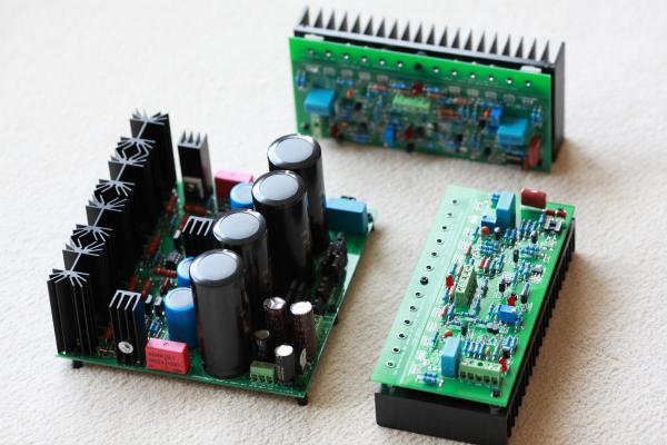
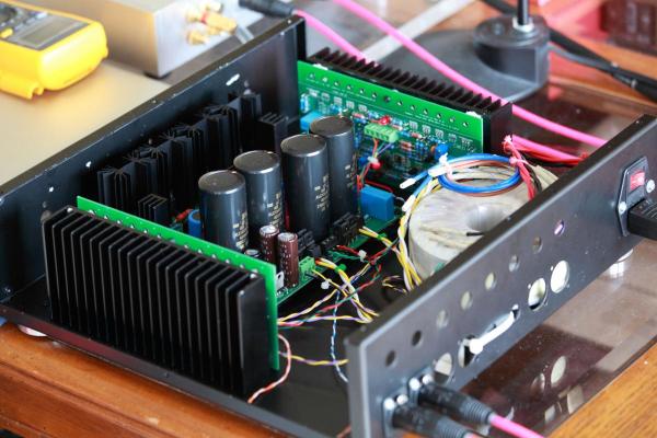
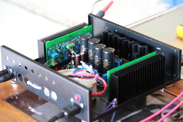
As promised, here are some pics of my build. I am embarrassed to post these pics but did not want to be disrespectful and anti-social This is my temporary housing. I can now start to think about what to do with chassis(s) for the amp. At this time I am leaning toward a 2-chassis route where the transformers and PSU are housed in a separate box. I plan to visit Taiwan later this year and hope to check for available options when I am there. For now, I needed to put the modules in a case so I can listen to it - did not like the idea of having modules operating on 400V + sitting all over the table connected with loose wires I still have lots of work tidy-up the wiring.
-
Thanks Kerry. Pardon an ignorant question, but your servo design, when adopted for the KGSSHV, supposed to work on top of the built-in servo?
-
On hindsight, I should have started with 1.5K instead of 2K in the R26 position. I had planned to do so while I was planning for the build just forgot about it when I sourced parts. I read Kerry's post but don't understand it - how does it differ from the servo on the board?
-
I will try post some pics tomorrow. This KGSSHV and SR007 combo is very addictive. I cannot stop listening to it. I went almost 5 hours straight last night listening to one piece after another. I am a newbie to the electrostatic transducer world but have been in the audiophile hobby for more than 30 years and I am hearing things I have not previously experienced. I am hooked. On another note, I am finding out the same thing others have reported - the temperature affects the offset quite a bit (but not the balance). The weather has gotten warmer yesterday and I could not get one channel's offset to below 5V. It's a bit cooler today and I mounted the heatsinks to the chassis which also contributes to the lower running temprature and I have no problem getting the offset on both channels to zero. I had planned to replace the 2K resistor in serie with the offset pot but may not need to do that any more. Hope sharing this experience will help some new builders. I have not plug the servo ICs in yet - want to observe a bit more so I have a better handle on how the balance and offset behave. Back to more music!
-
I have music! Wired up XLR connectors and the headphone socket from Justin. Hooked up the Buffalo DAC to the KGSSHV, plugged in the SR007, I have been listening to music for the past 2 hours and had a hard time pulling myself away from it to do anything else. Many many thanks again to Kevin for the ingenious design and Birgir, John, Pars and many others that helped me make this possible. Although I do not have anything other than a multimeter to test the amp and PSU, the KGSSHV is dead silent without signal feed. I think this can serve as a validation that the KGSSHVAMPV16MINI and KGSSHVPSMINIFINALSTN9360 Gerber files and resulting PCBs are good. Now I have to decide if I should continue to listen to music or get to bed...
-
Thanks all for your responses. I bought a bunch of Belden 83006 from hndme.com for this build. 22AWG, 19X34, silver platter copper, multistrand wire with Teflon coating. Rated at 600V, 200C. Easy and nice to work with. I primarily bought them for B+ wiring. I'll use them for wiring the amp to the socket as well. To eggil's question; I've read that Teflon insulation is preferred due to its superior dialectic property. I also find it to have good resistance to heat while soldering.
-
Thanks for your encouragement! Another question: what kind of wire do you all recommend using between the amp and the headphone socket? I’ve always preferred using 24 AWG solid core, pure copper wire for signal path based on things I read. In fact, I often use wires I harvest from the Cat5e cable. But this is the first time I build an amp to drive capacitive load.
-
Oh yes, I did have the rush all right - the rush of my heart beat! ) Well, I powered up both amp boards (kgsshvampv16mini) one by one tonight. Both boards seem to power up fine - all three LEDs light up and after about 25 minutes from cold start, I was able to adjust both balance and offset to 0V and from that point on they drift back and forth within a few volts (one of the boards I pretty much exhausted the last bit of the offset VR adjustment, I think the other one was close too). This test is done without the servo ICs installed. The power supply was very stable during the test, giving +15.15V, -14.97V, -405V, +408V and 558V bias. Not to say everything is rosy yet - I have not powered up both amp boards at the same time and still need to rig up all the wires and connectors so I can try to play some music through it. Thanks all for your help in getting me this far. Hopefully music is not too far away )
-
Thanks Kerry. You beat me to it and you are exactly right. The 7915 requires a minimum 5ma load to function. I found a thread on DIYAUDIO that explains it. It's a bit confusing since the 7815 positive regulator behaves differently. As it was explained at DIYAUDIO, even though the 7815 and 7915 appear to be complementary parts their internal constructions are very different. I put a 1K resistor across the output and I am getting -15.5V regulated output now.
-
Yes, it is a ST Micro 7915 negative regulator that I believe is causing the problem. Pars has previously posted that he had issues with ST Micro regulators as well. This does not inspire confidence at all - what is to guarantee that a working part may someday fail which is basically what happened in my case. What's the consequence of the +/- 15V supply goes out of balance by a few volts? Maybe those with running KGSSHV amps should double check? Is there a pin-compatible replacement part we can use? Edit: Just to set the record straight, the ST part L7915 is working as designed - it needs a minimum 5ma load to function.
-
Before I test the amp boards, I thought I give the PSU one more test and I ran into a weird problem on the -15V part which previously tested fine. The +15V tested fine. The power transformer is a Triad FS36-350 that I know Birgir has used. I wired the secondaries to provide a center tap. It tested fine without load (21v - 0 - 21v). I used a variac to test the regulator and here is the scenario: With the variac turned up to around 75v, the - output showed -14.96V and stayed there till the variac output past around 85v, from this point on, turning the variac up continues to raise the, supposedly regulated, output till it hits over -18V when I quit. Meanwhile the + out hits +15.17V at 75v and remains there since. Another weird thing, when I turn down the variac and keep monitoring the -out, it would gradually and continuously decrease and hit -14.96V and then stay there for a few seconds and then continue to decrease afterwards. So what gives? Any one has a logical explanation? I am guessing the 7915 regulator is probably bad but I cannot think of a logical explanation of the "magic" -14.96V phenomenon.
-
Thanks JoaMat and Birgir and Kevin.
-
The description says the boards are 4mm thick. Wonder how much the accounts for the high price?
-
Now that I have a variac, should I use it to test the amp board (kkgsshvampv16mini) as well? Since there are two voltage sources for the amp and I use separate transformer for the +/- 15V supply, which is the correct ( or better ) procedure? 1. Hook up both transformers to the variac and test the entire circuit (PSU and amp) through the variac. 2. Only hook up the high voltage transformer to the variac. Power up the +/- 15V part fully upon turn on and use the variac to gradually bring up the high voltage part. Thanks!
-
I have a 1000ohm ceramic resistor I use to bleed out the large smoothing capacitor in the past for other projects. Is it safe to use for this purpose? I assume I wire it across the ground and either the + or - out? Thanks!
-
I tested my kgsshvpsminifinalstn9360 build today and it appears to be running fine. Please see my post on the kgsshv main thread. Please also share your experience if you have completed building the kgsshvpsminifinalstn9360 and/or kgsshvampv16 mini! Thanks!
-
I think I have a minor success to report on my kgsshvpsminifinalstn9360 PSU build. After replacing the rectifier diodes with the correct STTH512FP parts, using my freshly arrived variac, I powered up the PSU successfully, and I measured -406V, +408V and bias voltage 560V (from test point) after about 15 minutes. These are the correct numbers I was expecting based on my setup. I did not notice any smoke, spark or abnormal temperature during this brief testing. The +/- output voltage was very stable, varying around 1V from start up till the end of the 15-min testing period. The bias voltage raised about 10V during the same time. I do not have the equipment to measure noise and such but I hope this is enough evidence that the PSU board is fine. If so, this is good news for the GB participants who have received this board. I have some work to do to complete the amp boards (kgsshvampv16mini) and start testing them. Please let me know if there are additional testing I should and can run with my Fluke 112 meter to make sure the PSU is functioning as designed. Many thanks again to all that came to my rescue with my problem. P.S. A word of caution for safety - the bias voltage sustained much longer than the +/- outputs after powering down the PSU. When the output voltage dropped to below 1V after a couple of minutes the bias voltage still measured well over 100V!!!
-
Sorry, using my Chinese combined with long-forgotten and very limited Japanese, I was not able to find out if the pinout on the datasheet Laowei attached was bottom or top view. All I can say is that the datasheet did not state one way or the other. I did find another 6ra6 pinout diagram which looks exactly the same but with "T7C" text below it. Not sure if this means anything. I could not find any information relates to "T7C". FWIW, couple of Japanese sites on tube history state that the 6ra6 was created as an "improvement" or "alteration" of the 6s4a tube.


