mwl168
High Rollers
-
Joined
-
Last visited
Everything posted by mwl168
-
Did some testing on my GRLV PS. For +/- 20 VDC regulated output, the drop out voltage is about 3 VDC. Very impressive to me for such a high performing regulator.
-
What are the pro and con using LM4040 vs LT1021 for voltage reference?
-
The GRLV PCB is from the GB I ran in 2015. As Sorenb pointed out, this version does not accept CT transformer. There is a BOM in the GB thread which is what I used to source the parts for this most recent build. Do remember to make adjustment needed for your targeted output voltage. IT's a cracking PS. I've built 3 so far. Having a hard time keeping pace with Sorenb. As to why it sounds different; there may be a few factors. In addition to the ones I already mentioned, I did also use different filter and bypass capacitors both on the PS and on the amp. Of course it could always be the wiring between my ears Will report back if I can confirm my findings so far and figure out what contributes to the difference.
-
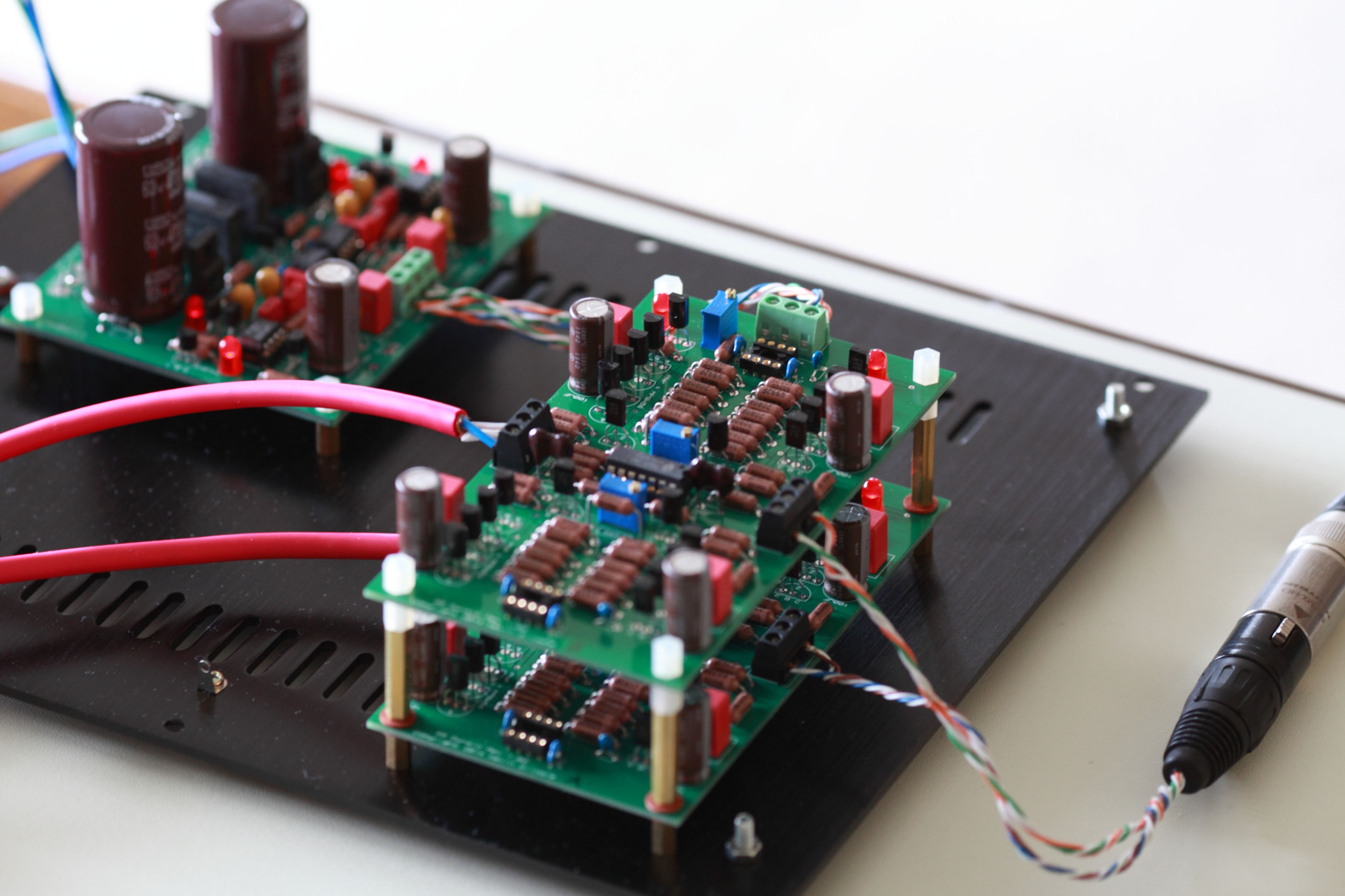
Just started testing a second SS Dynalo I am building for a friend. This one is also powered by a GoldenReference PS running 20VDC rails. 255 ohm bias resistors (R38/R39) resulting in 300mV voltage drop over the 20 ohm emitter resistors so about 15mA per MPSWx6 devices. Bolted the pass transistors of the GoldenReference to the chassis. After 3 hours running, the temp of the pass transistors is about 35C and 64C for the MPSWx6 devices. For whatever reason, this one seems to sound quite a bit better than my first one. It may be due to better soldering job, the fact I tuned the offset correctly (thanks to information from Kevin and Pars) or better combination of supply voltage and output current. EDIT: forgot to mention, I also cleaned the flux residue on this build which I did not do for my first one (did not start following this practice till I built my first high voltage Stax amp ). Maybe this also contributes to the better outcome. Needless to say, I went back to clean the flux on my first SS Dynalo

-
Maybe Kerry can help verify. I have both Aavid 7721-3PPSG and 7721-10PPSG. The 7721-3PPSG has longer shaft than the 10PPSG (3.18mm vs. 2.41mm). But in my case, I was not able to fit the 3PPSG into the tab hole of the TO220 transistors. I ended up using the 10PPSG for all my builds. There are others that have experienced similar issue and some had to enlarge the tab hole to make the 3PPSG fit.
-
At that rate it may be cheaper to build Kevin's BJT version of the Blue Hawaii from scratch!
-
Perhaps a bit off topic, but all jokes aside, did you build the HV Carbon? I have both the KGSSHV and Carbon, from my experience, without servo, the KGSSHV does take longer (20 minutes +) for the balance and offset to settle than does the Carbon. Subjectively, the heatsink on my Carbon also reaches stable temperature faster. Both factor are likely related. The opto servo on the Carbon pretty much starts working soon as the amp is powered up. I never did engage the servo on my KGSSHV. Cannot speak to how long it takes for either amp to reach optimal performance from cold start.
-
-
-
-
-
-
Thanks JimL. An additional data point to add; while I was testing and using the SRX Plus, I also measured the tube temperatures using an infrared gun pointing at the plate of the tubes. As perhaps a testimony to JimL's point; both the 12AT7 and 6SN7GTB were running at surprisingly (to me) low temperature. IIRC, the 12AT7 was at around 65C and the 6SN7GTB at around 120C. These temperatures measured the same after I accidentally left it on for 14 + hours. EDIT: corrected the temperature unit of measure
-
Accidentally left the SRX Plus running overnight. So as it sits now it's been running continuously for more than 14 hours. Happy to report that it appears to be very stable, the offset and balance all measured as expected and all the heatsink temperatures are steady as well. No, it does not sound better than say, after a couple hours of warming up but it's very good to know that the amps is very stable and my ignorance did not set the house on fire.
-
I built a SuSy Dynalo and I really like it with my LCD-2.
-
A quick update on the buzz. I finally traced the buzz to noisy 12AT7 tubes. Once I replaced the noisy tubes the amp is silent without input signal. As JimL advised, I twisted the AC filament wires tight, keep them away from the input stage as far as possible and also arrange them so they are perpendicular to the signal traces.
-
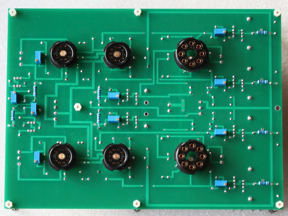
Hi Kerry: I got them from eBay: http://www.ebay.com/itm/130301072783?_trksid=p2045573.m570.l5999&_trkparms=gh1g%3DI130301072783.N36.S1.R2.TR11 They are bakelite material. Good price and works great so far
-
Not possible on the current PCB to install the 10M90S resistors on the other side. As is, the heatsinks do not get too warm running 330VDC rail and 7mA output current in open air. I measure about 51 degree Celsius (about 123 F) after 4+ hours of continuous running. It'll obviously run warmer once cased. I am using 38.1mm tall heatsink (Mouser part # 532-529801B25G) and there are taller ones available.
-
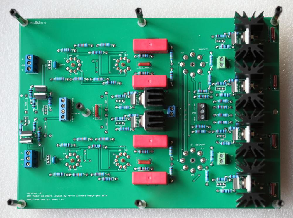
Now that the SRX Plus has been running for a few days and seems stable, I thought I would share some information that others may find helpful for initial testing. Congo5 was kind enough to share similar information with me that really made my testing much straightforward. As I mentioned in earlier post, I adjusted the value of the fixed resistors in series with the source pin of the DN2540 and the trim pots based on the recommendation from both Congo5 and MLA. So for the 7mA output current source, 17mA output current sink and 1.1mA (based on 300K 12AT7 plate resistors) input current sink as JimL recommended, here are the approximate mean of the trim pot values I end up with: Output current source (100 ohm): 35 ohm (200 ohm fixed resistor) Output current sink (20 ohm): 12.5 ohm (75 ohm fixed resistor) Input current sink (500 ohm): 410 ohm (1.2K fixed resistor) To adjust for balance of the input stage, I put the DVM probes on the two .22uf/1000V coupling caps where they are connected with the plates of the upper 12AT7 then adjust the 5K trim pot until the meter reads approximately 0 VDC which sets both the plates of the 12AT7 at the same voltage relative to ground. I then re-adjust the 500 ohm pot as needed so the 12AT7 plate voltage sits at mid point of the B+ and ground (167 VDC for my SRX Plus which runs on 330 VDC rails). As to how does it sound? It's a different sound signature than all other KG ES amps I have built (I don't have a Megatron or DIY T2). I am guessing it's the nature of an all-tube circuit. It's surprisingly spacious and punchy sounding to me for such a minimalistic circuit. I think the cascoded CCS is really doing its job. I like it very much. I hope more people will build it.
-
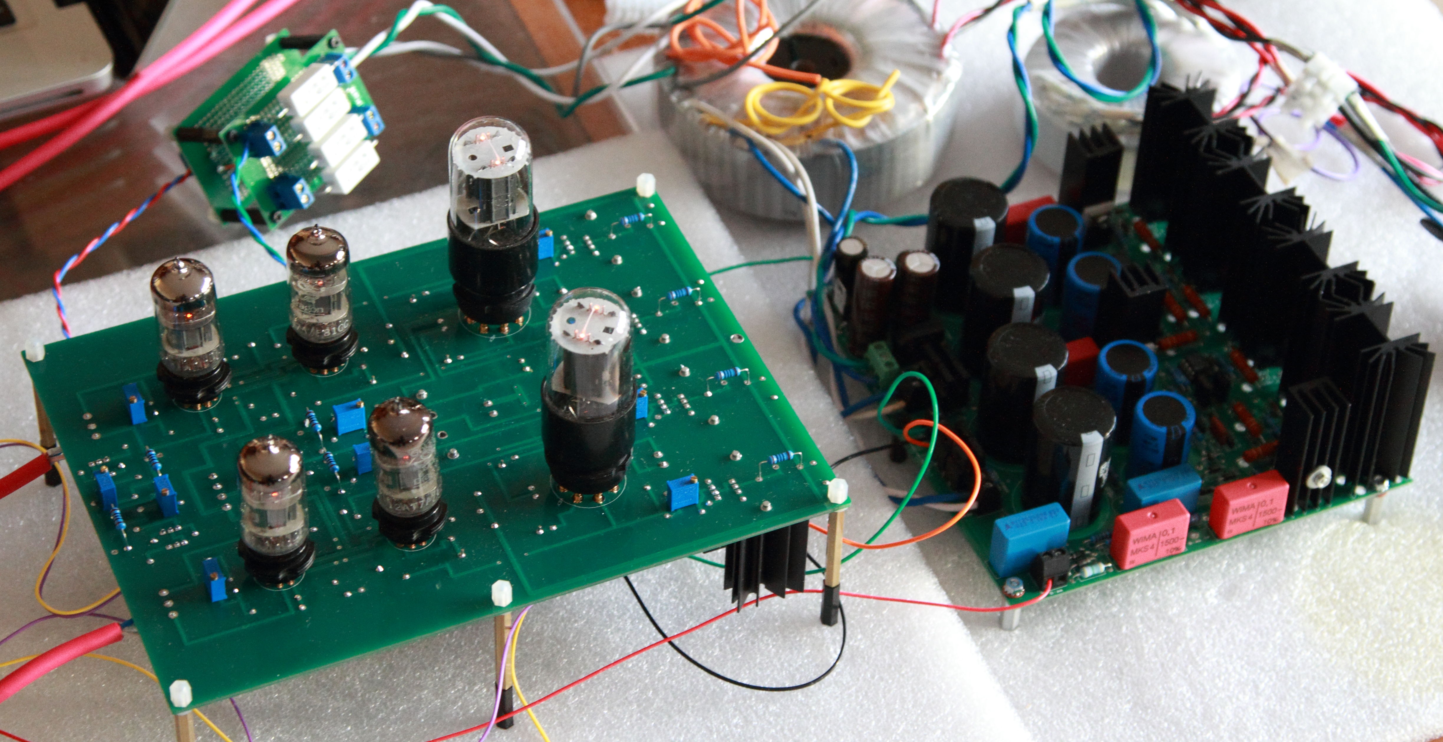
Thanks JimL! What you advised were the first things I tried. After some experiment, it seems to come down to one of the 12AT7 tubes after I started swapping tubes around. Once I knew the amp is working, I did rearrange and tidy up the wiring up a bit in my testing setup. I am still not 100% sure though but happy to report it seems to be buzz-free at the moment. As is customary, here are some pics of my build. As you can see I put the trim pots and the 100R resistors on the top to make it easier for testing and tuning. The gizmo next to the amp board is something I rigged up to lower the AC filament voltage. I am really liking the sound of this amp even with the cheapo tubes I am running with at the moment.

-
I forgot to mention that I am using 4 made in China Golden Dragon 12AT7 and 2 GE 6SN7GTB I randomly took from my parts bin for this initial testing. I don't know if they were matched or not. But simply by adjusting and balancing the upper 12AT7 plate voltage (they were off by roughly 15VDC with the 5K pot set in its mid-point) and leaving the output current source and sink at their pre-dialed current setting, the output balance are within 2 VDC and the offset under 4 VDC once the amp is warmed up and that's where I left it. Maybe I got really lucky with the tubes I use.
-
I have been listening to my newly built SRX Plus for the past 2 hours or so. I am using a reconfigured KGSSHV PSU to supply the HV (+/- 330 VDC) and a -15VDC for input stage current sink. The build was pretty straight forward. I did change the value of the resistors in series with the trim pot of all the cascoded CCS as advised by both Congo5 and MLA. Specifically: Output current source: 200R in place of 250R Output current sink: 75R in place of 102R Input current sink: 1.2K in place of 1.43K The DN2540 has quite a bit of variance from sample to sample even from the same batch so be prepared to adjust these value for your build. I am running 7mA output plate current, 17mA for output current sink and adjust the input current sink (the 500R trim pot) so the upper 12AT7 plate voltage is half way between ground and B+ (167VDC for my build) and adjust the 5K trim pot so both the plates of the upper 12AT7 sit on the same voltage. I do have a very slight buzz on one of the channels that is not attenuated with volume. I need to trouble shoot it. It happens to be the channel where my AC heater supply wires pass below but there could be many other causes. Thanks to JimL for coming up with this modified SRX circuit, Kevin for laying out the PCB and JimL, Congo5 and MLA for helping me along my build.
-
I may be stating the obvious but the TL081 is rated at +/-18VDC max supply voltage. The OP27 is rated +/- 22VDC, OPA445 is rated up to +/- 45 VDC.
-
I have a dumb question. How do you supply the power needed?
-
I bought a few aluminum chassises from VT4C before. The QC is non-exisitent. One of the chassis is impossible to put together due to serious misalignment. One of the chassis cover was not even rectangular. Don't have experience with their other products.