mwl168
-
Posts
1,377 -
Joined
-
Last visited
-
Days Won
1
Content Type
Profiles
Forums
Events
Everything posted by mwl168
-
Did you measure the PZTA42 Vce between the two channels before making the mod?
-
Did you take another measurement after the amp warmed up? Channel 2 PZTA42 Vce don’t look right. It’s also odd that it happens to both PZTA42 and yet the voltage drop across the 20K is correct?
-
I first came across this group here...
-
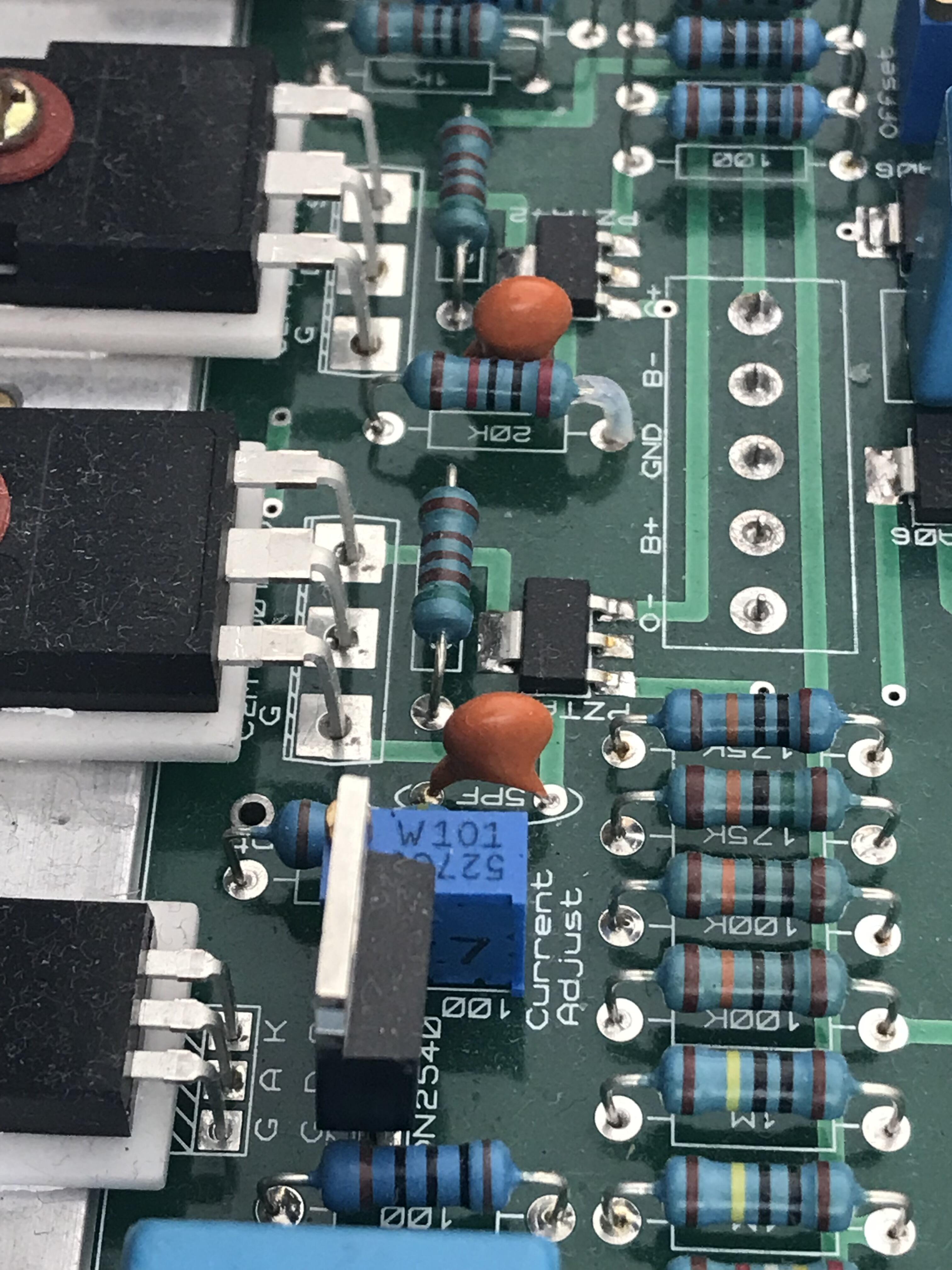
So I did indeed install 150K and 200K chain for the bias resistors of the C2M1000170D when I first built my Carbon. Today I replaced the 200K with a 150K, I had also dialed the bias back to 18mA and disengaged the servo. Then took a few measurements after letting the amp warmed up. Now the PZTA42 Vce is around 13.7V, voltage drop of the 20K R is 25.4V and the Vgs of the C2M1000170D is around 3.3V. And I did not blow up the amp.
-
Got it. Thanks. I got work to so then.
-
Thanks MLA. That was what I was thinking too. Then I don't understand why Simmconn was worried about exceeding the C2M1000170D's max Vgs rating? Here is an interesting thing - I went back to my PM's and could not find anything that discussed this mod to the 175K+175K bias resistor chain. However, I came across an early correspondent with Kevin about my plan to use 200K+150K instead (values I had on hand at the time). Now I wonder if the one that looks like a 100K may be in fact a 200K. It's hard to tell visually. I can desolder the resistor in question and measure it. But part of me, the lazy part, is thinking if all is well why not leave it along? Maybe between the +/- 406VDC rails and the 20mA bias current somehow puts the PZTA42 Vce in the desired region?
-
Today I decided to make this mod to my Carbon I built in 2015 and parallel a resistor to one of the 175K to raise the Vce of the PZTA42. My Carbon is running on +/-406VDC rails and 20mA bias. To my surprise, instead of the 175K + 175K bias resistor chain, I had already replaced them with 150K + 100K at some point. As such, I measured Vce = 10V for PZTA42 and 21.8V drop across the 20K resistor. According to the graph above, this should put the PZTA42 in its linear operating region. Some wise man must have suggested this mod to me (I suspect SorenB) very early on. However, I measured Vgs of the C2M1000170D to be only 3.2V. Based on how I understand simmconn's posts, I was expecting 20V or higher. What gives?

-
Happy Birthday Day Nate 🎂
-
IIRC, I encountered a similar “issue” when I was adjusting my Blue Hawaii first time I powered it up. As Kevin already said, it turned out my offset pot was way off range. Once I got the offset adjusted to within reasonable range, the balance started to fall in place as well. I need to find the schematic but sometimes it’s necessary to change the resistor value that’s in series with the offset pot to be able to adjust the offset to 0V. Good luck!
-
@spritzer: You are correct - re: the two hand-drawn schematic; first one says “3ES pre-amp section”, second one says “3ES electrostatic headphone amp section” on top and “same for 4 channels” at bottom, the script in the rectangle in the schematic says “3ES amp module”. According to the OP, the pre-amp section is “ tube-input and tube-output”, headphone amp section is “transistors”.
-
I would be very wary of buying hard to get parts from aliexpress. In these high voltage applications, a fake part that breaks down can easily cause catastrophic and expensive failure.
-
I use M5 and find it good for that job.
-
Happy Birthday Jose! 🎉
-
Amanero USB receiver, TPA Buffalo DAC, Mercury I/V stage. Plus a tube output buffer?
-
These are only rated for 300V so need to be mindful where they are used.
-
Happy Birthday Chris
-

Megatron Electrostatic Headphone Amplifier
mwl168 replied to kevin gilmore's topic in Do It Yourself
@JoaMat: I see you have been using Mundorf Silver/Gold/Oil capacitors in the coupling positions of your Megatron. These caps are rated at 600vac/1000VDC and being an oil-impregnated caps they are susceptible to high temperature (factory rating is up to 85C/185F). Also, the Megatron PCB shows the coupling caps between 12au7 and 12ax7 rated at 600v and 1000v for the caps between the 12ax7 and EL34. Have you experienced any issues with using these Mundorf caps in Megatron over time? -
Did you see the for sale section where there is a used BHSE offered for sale in England?
-
I don't know what Martin thinks but Michael thinks freestanding on the PCB will be fine 😉
-
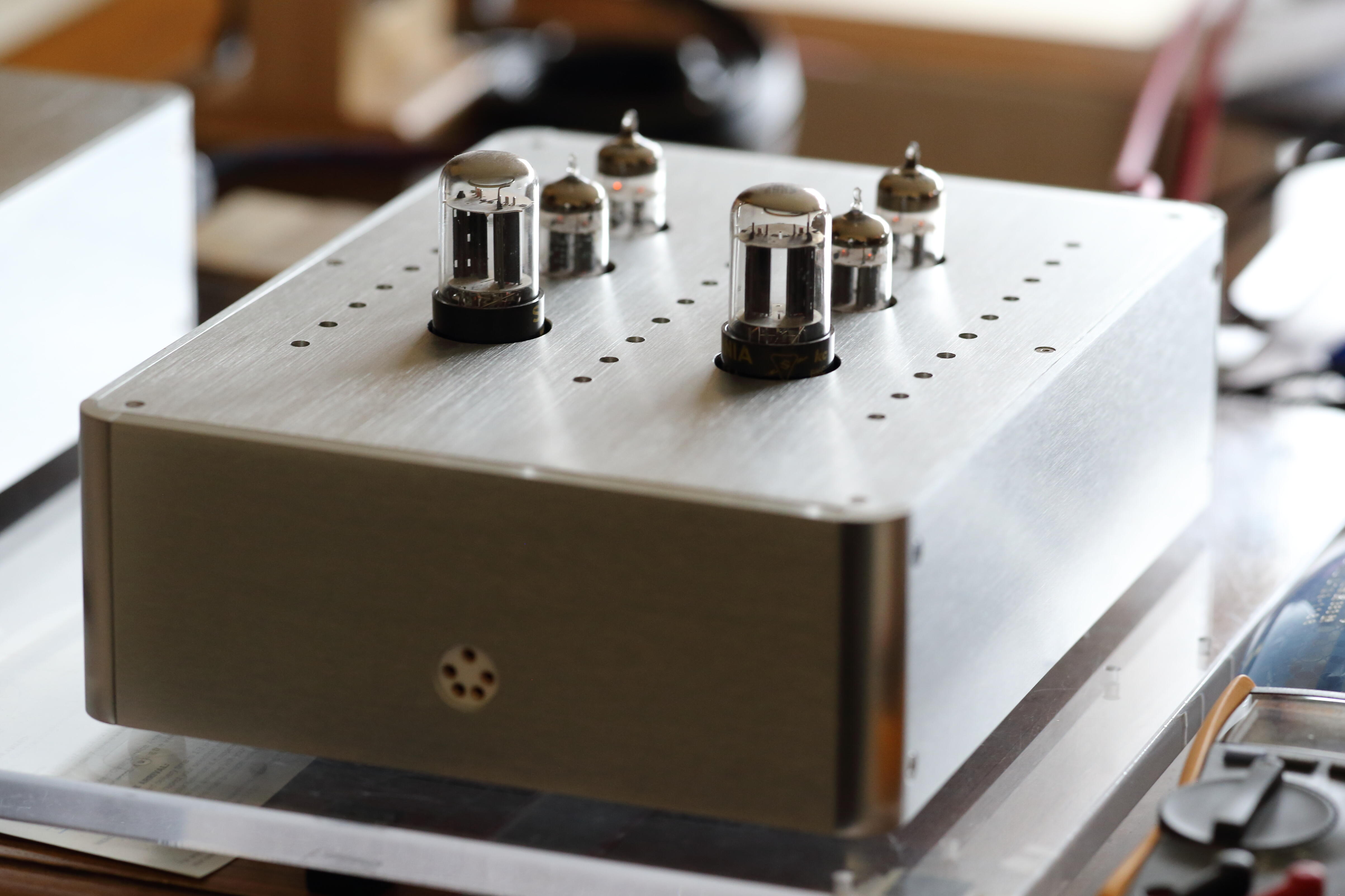
Hook up this little gem today with the SR009 after a long break and just let the music flow...
-
Kevin can confirm but I am pretty sure you'll be fine - the current draw is very minimal like a few 10mA IIRC. Unless you are dropping some unusually high voltage through the GRLV there is not much heat to dissipate for the MJW21193/21194.
-
It certainly got the family look. Maybe someone at Dyson got creative with spare parts from their vacuum cleaners.
-
Hmm, that is odd. Sorry, did not read carefully that only one of the two channels behaves abnormally. Did you check if both channels have the same output bias?
-
This "Normal" behavior has been my experience as well but I also found the magnitude of offset drift is closely related to the case temperature of the output device too. Does the heatsinks of your Carbon get significantly warmer when the amp warms up? I am theorizing that if the amp has oversized heatsink that barely gets warm the offset may drift much less. But this is just a guess.
-
The Official Head-Case Photography Thread.
mwl168 replied to Knuckledragger's topic in Miscellaneous
Allow me to help solidify your point...