-
Posts
1,376 -
Joined
-
Last visited
-
Days Won
1
Content Type
Profiles
Forums
Events
Everything posted by mwl168
-
I took the AC filament directly off the windings of the Antek transformers for the BH and GG. And yes, B+, B-, bias and +/- 15V for the JFET front end (I use +/- 18V) are all you need for Carbon. Add filament supply for GG and BH. Plus supply for the HV delay if you decide to implement it (I recommend you do).
-
I need to correct myself. The above statement should be "Both boards have the built-in HV soft-start circuit...". The soft-start circuit is intended for HV delay but the "delay" part needs to be implemented separately off board. There are many such delay modules available on eBay or you can simply wire a manual switch like I did.
-
The first and third boards in your pics are what commonly referred to as the GRHV dual boards. First board contains B- and 7815/7915 LV regulation. Third board contains B+ and bias (+580VDC) supply. Both boards have the built-in HV delay circuit. For Carbon, GG and BH they are all you need but you can replace the onboard LV regulator with the GRLV. Most builders seem to be using ac filament supplies (myself included). The second board looks to me like what Kevin has laid out for a different purpose. IIRC, it contains a B+ supply and regulated filament supplies. It’s what I plan to use for JoaMat’s mini T2 build for front end tubes plate B+. You can use it for the same purpose on the Megatron but many simply use a drop resistor from the B+. The other GRHV boards are basically different dimension boards Kevin laid out to accommodate different chassis layout options. Other than that some earlier version boards do not have the built-in HV delay circuit, they are all the same identical circuit.
-
Enjoy your beer ?
-
My experience and logic with the CFA amp echo what Jose said. Both the BH and Megatron cost lots more and are much more complicated to build than the CFA and I do prefer my BH and Megatron to the CFA on an absolute scale. Yet the CFA is a very nice sounding amp in its own right. To my ears it has a very organic and musical sound signature. If I state my personal preference between the three KG-designed all solid state amps I have built (CFA, Carbon and KGSSHV), some people will probably be choking their beer through their noses. Kevin can correct me if I am wrong but I think the electrostatic CFA amp is meant to be an easy and low-cost to build amp and it just ends up punching well above its class. The dynamic CFA on the other hand is a different story! Just my own 2 cents worth.
-
22.5mA current is a lot for a push-pull amp so you can reduce it quite a bit to manage the heat. Changing either the 2K or 500K accomplish the same thing - IIRC, they form a voltage divider. Curious to hear what you think of its sound compared to your other amps.
-
Base on the Toshiba 2SK170 and 2SJ74 datasheet, with the marking side of the JFET facing you, the left-most pin is the drain and the right-most pin is the source.
-
Thanks Jose. It still looks to me that the drain pins are inserted into the emitter slots?
-
Thanks Jose. I think you meant P channel (J74) on top and N channel (K170) on bottom? Also, looking at the photo, it looks like the D pin of the JFET is inserted into the E slot of the socket?
-
So I am confused now with the JFET - BJT pin mapping looking at the photos and posts in this thread. It's clear that BJT Base -> JFET Gate. Knowing that the Toshiba JFET Drain and Source are interchangeable, which one is theoretically correct? BJT Collector -> JFET Source, BJT Emitter -> JFET Drain OR BJT Collector ->JFET Drain, BJT Emitter -> JFET Source
-
IIRC, years ago I used the IRC 0.1% resistors to build my first Dynalo. I measured each of the resistors when I received them and I was not impressed with the accuracy and the tolerance of those I received. I have since adopted the practice of spending the same (or less) money and buy large quantity of good quality 1% resistors and hand pick and match them. Personally I think I have better outcome with the latter practice.
-
It may help to know if the purpose of the exercise is to only match same spec'ed resistors to each other or if the absolute accuracy of the resistor value is also critical.
-
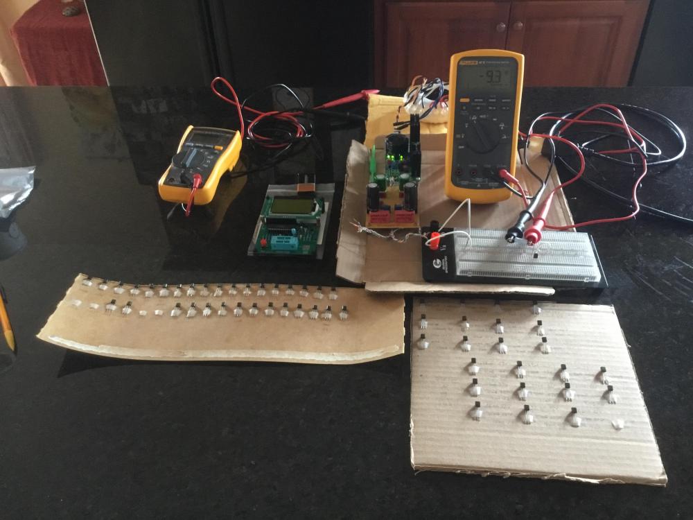
So I rigged together the test circuit both Jose and Chris suggested that used a 12VDC supply and measured the whole batch of 2SK170BL and 2SJ74BL (12 each). The 2SK170BL IDSS measured between 7.7 - 11.2 mA, the 2SJ74BL measured between 7.0 - 11.0 mA but mostly between 8.0 - 11mA. Toshiba datasheet states 6 - 12mA for BL grade. The good news is that the relative measurements between samples are consistent with those from the ATMega 328 tester. I am pleasantly surprised that I should be able to find 4 pairs of K170 within 3% and 2 pairs of SJ74 within 1% and another 2 pairs within 5% of these random samples. Not great but OK. Unfortunately the match between P and N channel pairs are not nearly as good. Forgot to mention; if you are going to do this, make sure you do it in a constant ambient temperature environment and you sit a good 2 + feet from the sands being measured. For a while the measurements were jumping all over the place only to find out it was caused by my radiant body heat. Christ!
-
Hmm, relatively consistent with my measurements but way off from what the datasheet states. Wonder if I am not reading the datasheet correctly or something else is amiss?
-
Thanks all. That’s very good to know. Also happy to know the 2SJ74’s appear to be authentic and the tester is not defective. It’s almost funny - the cost of 3 of those SJ74 exceeds what I paid for the tester. Jose, do your testers show similar SJ74 results as what I posted (value wise)?
-
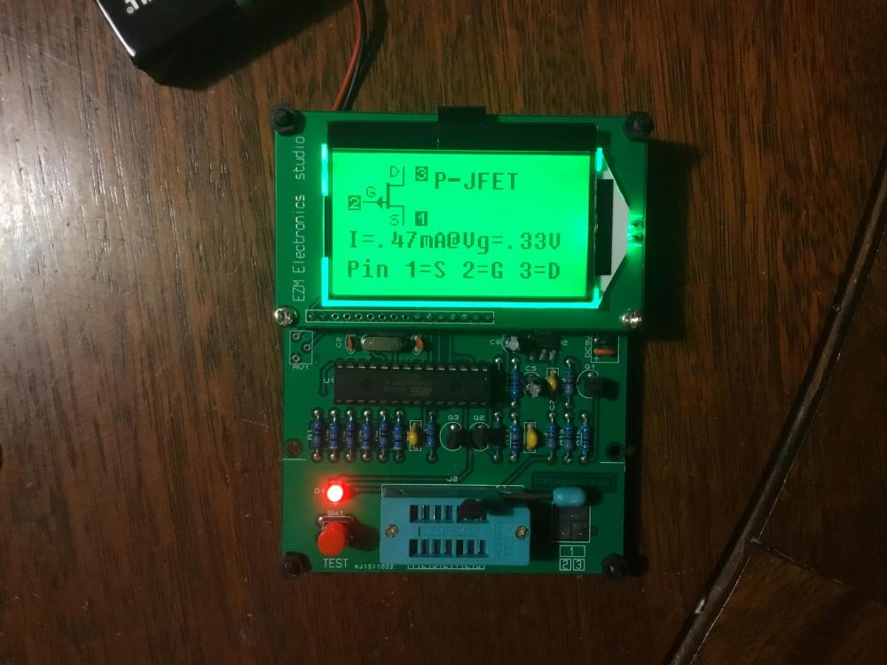
I received a batch of 2SJ74 and 2SK170 from BDent today. I proceeded to test them using one of those ATMG328 testers I got. Interestingly, the tester shows the 2SJ74 pinout to be 1=S, 2=G, 3=D, the S and D pinout are reversed from the datasheet. What gives?
-
Kerry Design mini GRHV\GRLV and JoaMat mini T2 Group Buy
mwl168 replied to mwl168's topic in Do It Yourself
Table updated. -
Kerry Design mini GRHV\GRLV and JoaMat mini T2 Group Buy
mwl168 replied to mwl168's topic in Do It Yourself
Table updated. -
Post a clear picture of the board will help to diagnose the problem. Did you check and make sure you have the correct resistors populated? Maybe start with the current limit resistor and the ones that determine the output voltage?
-
Kerry Design mini GRHV\GRLV and JoaMat mini T2 Group Buy
mwl168 replied to mwl168's topic in Do It Yourself
Table updated. -
Ok. This is making more sense now. @MartinC700 : It is a good idea if you pre-adjust the CCS using what JoaMat and steefdebrijn described, there are other variables will come into play when you actually power up the amp. You still need to fine-tune the CCS once you actually power up the amp and allow it to warm up. Again, be careful when you make adjustments with the amp on. These HV applications are not forgiving and it’s easy to accidentally short something or get electrocuted. Many of us had that unpleasant experience, myself included.
-
Hmm, I am confused by your question. What do you mean by “using the LV supply to adjust the current”? The bias current of the amp is set by the CCS. You use the trim pots in the CCS while measuring the voltage drop of the test points to set the bias current. Glad to know that you fixed the HV supply.
-
Thanks Chris! I do have MPSW parts on hand but would like to save them in case I need them for other applications. The differences in spec are that MPSA parts are rated for .650W dissipation (vs 1W for MPSW parts) and .25V collector-emitter saturation voltage ( vs .4V for MPSW parts).
-
For the off board version can I safely use the following substitute parts? MPSA06/56 for MPSW06/56 MJF15030/15031 for MJE15030/15031
-
Thanks Jose. And, yes, I will be building an "off board" version and most likely with a dual-mono GRLV power supply.


