mwl168
-
Posts
1,376 -
Joined
-
Last visited
-
Days Won
1
Content Type
Profiles
Forums
Events
Everything posted by mwl168
-

Kerry Design mini GRHV\GRLV and JoaMat mini T2 Group Buy
mwl168 replied to mwl168's topic in Do It Yourself
Table updated. -
Kerry Design mini GRHV\GRLV and JoaMat mini T2 Group Buy
mwl168 replied to mwl168's topic in Do It Yourself
posted BOMs in the first post of this thread. The BOM for GRHVxxx and PSU MAIN boards should be up to date. Need to check the GRLV boards BOM. -
Kerry Design mini GRHV\GRLV and JoaMat mini T2 Group Buy
mwl168 replied to mwl168's topic in Do It Yourself
2 GRHVxxx boards are needed for the PSU. GRHVxxx are not needed for the mini T2 boards. -
Kerry Design mini GRHV\GRLV and JoaMat mini T2 Group Buy
mwl168 replied to mwl168's topic in Do It Yourself
Table updated. It's time to wrap up this GB. Please post your decision for partially-assembled/bare GRHVxxx boards and updates to the PCB quantities by end of Sunday, March 22. I will then get quotes from the fab house and start collecting payments so we can place the order to have the boards made. Again, I would assume you opt for assembled GRHVxxx boards for those that do not respond. For those GB participants that are new to Headcase (less than 10 posts) and have not responded since last Tuesday, March 10, please post your response here so we know you are till participating. -
Kerry Design mini GRHV\GRLV and JoaMat mini T2 Group Buy
mwl168 replied to mwl168's topic in Do It Yourself
Table updated! BOM for boards will be posted soon in the first post of this thread. -
Kerry Design mini GRHV\GRLV and JoaMat mini T2 Group Buy
mwl168 replied to mwl168's topic in Do It Yourself
Hi Purk: I don't believe you had joined the GB earlier. Can you specify which and how many boards each you want? Table updated. -
Funny you should say that... In the late 70's, early 80's when big ass amps with big ass meters were all the rage, there were companies in Taiwan that sold amps exactly like that. Except inside the large amp chassis were tiny transformer and circuit boards etc. that could easily fit in a chassis 1/4 the size. I've even heard that some companies actually put brick inside the chassis so the weight is also there although I've never actually seen one.
-
I could not sleep last night, it must be because I looked at that photo last night with those behemoth amps stacked on those weaselly wood shelves. I looked at it again closely now and it appears that there may be some additional support in those two shelves below. But still... How did one get those amps in that space in the first place?
-
Kerry Design mini GRHV\GRLV and JoaMat mini T2 Group Buy
mwl168 replied to mwl168's topic in Do It Yourself
Table updated. Blank in the GRHVxxx-bare column indicates that the participant has not responded on this thread to indicate the preference for bare or partially-assembled boards and is deemed to opt for partially-assembled board by default as previously communicated. -
Kerry Design mini GRHV\GRLV and JoaMat mini T2 Group Buy
mwl168 replied to mwl168's topic in Do It Yourself
I received updated quotes from the fab house. These quotes are for partially assembled GRHVxxx without the following parts: C2M1000170D (through-hole part to be mounted on heatsink) IXCY10M90S (potential wait due to lead time) R7, R8, R9, R10 (resistors that set up regulated voltage) C2 (Do not populate) 150 pcs - $49/pcs 60 pcs - $60/pcs The GRLV boards can work as direct plugin for the 78xx/79xx parts. Given the number the GB is at currently, I doubt it a few more sets of mini T2 boards is going to make significant difference in cost. Won't know for sure until I provide the actual quantity for the fab house. -
Kerry Design mini GRHV\GRLV and JoaMat mini T2 Group Buy
mwl168 replied to mwl168's topic in Do It Yourself
I already requested for quote of 50 partially assembled GRHVxxx boards. This new quote should give us a sense of what to expect. -
Kerry Design mini GRHV\GRLV and JoaMat mini T2 Group Buy
mwl168 replied to mwl168's topic in Do It Yourself
Got quotes back from the fab house (PCBnet). All dollar amounts are USD. All boards are green, 2mm thickness. mini T2 board: $24/pair with 3oz copper (52 pairs) PSU main board: $10 with 3oz copper (72 pcs) GRLV78: $5 with 2 oz copper (92 pcs) GRLV79: $5 with 2 oz copper (92 pcs) GRHVxxx (bare PCB): $4 with 2 oz copper (150 pcs) GRHVxxx (partially assembled): $55 with 2 oz copper (150 pcs) Note that the quotes are based on quantities. The cost goes up if the quantity goes down. A few details about for the GRHVxxx partially assembled boards: 1. The following parts are not populated: C2M1000170D (Q3) - through-hole part to be mounted on heatsink R7, R8, R9, R10 - resistors to set up regulated voltage C2 - do not populate 2. Parts cost with the Mouser BOM I put together is roughly $28 without the parts listed above. The complete BOM is about $36. Tax/shipping excluded. Basically, you are paying extra $23 per board to have it pre-assembled. 3. There is a potential wait for IXCY10M90S parts (2 needed). I think we should opt to have this part un-populated if there is a long wait. There are two IXCY10M90S on each board and they are easy to solder. This will also bring the assembled PCB cost down by about $5. What we do next to move this GB forward: All GB participants please give it some thoughts if you like to go with bare or partially assemble GRHVxxx boards and post your decision on this thread ASAP so I can update the table and get final quotes. If you decide to go with bare GRHVxxx boards, you may consider getting extras just in case. I would assume you opt for assembled GRHVxxx boards for those that do not respond. -
Kerry Design mini GRHV\GRLV and JoaMat mini T2 Group Buy
mwl168 replied to mwl168's topic in Do It Yourself
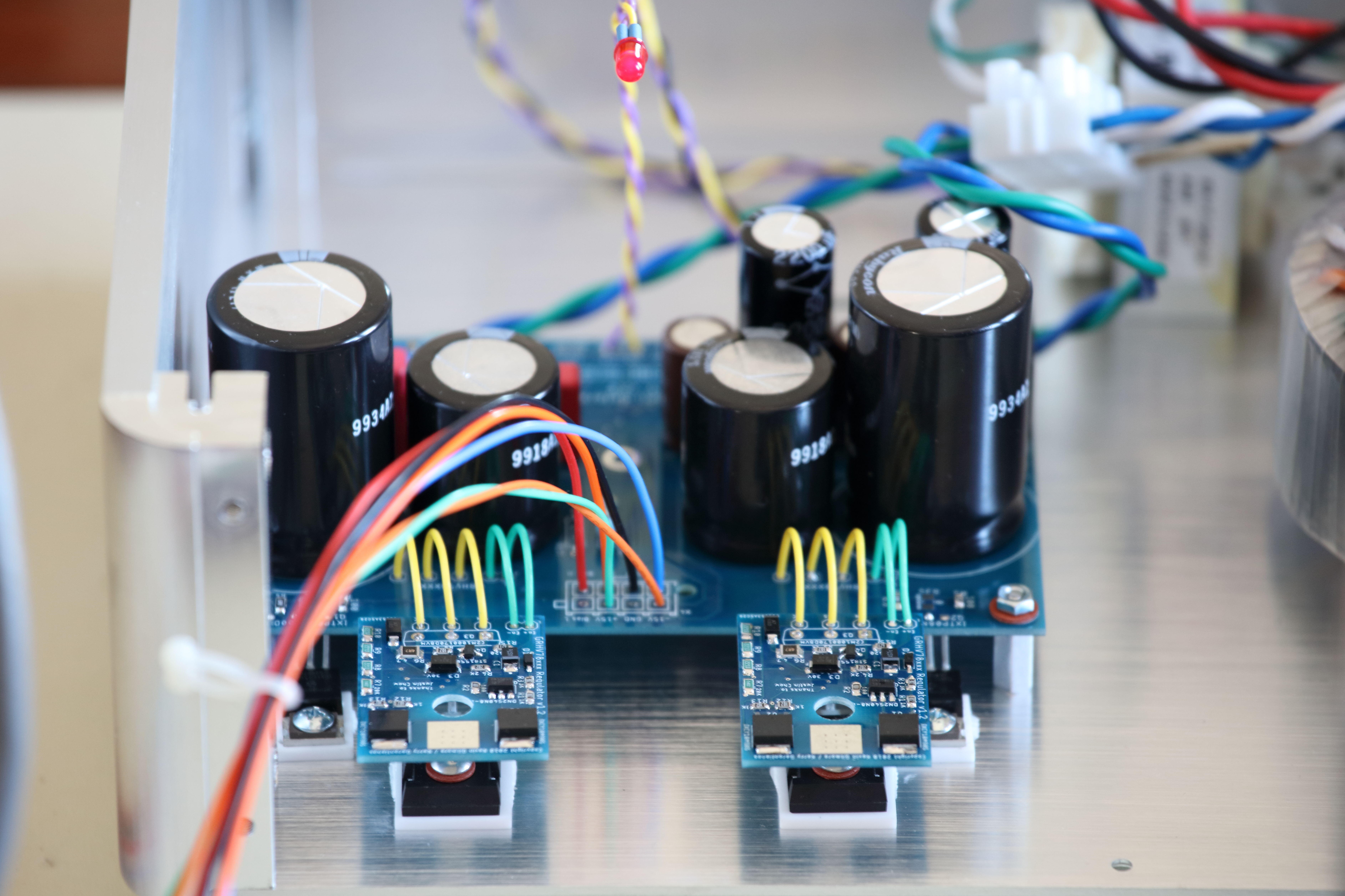
Made good progress this weekend testing the PSU main board and the GRHVxxx. Everything tested works as designed. The LED has a cool feature - it blinks at power on till the timed delay kicks in then the B+/B- are turned on and the LED stays on constantly. Photoed is my test setup powering my electrostatic CFA. GRHVxxx set up for 339VDC rails intended for my SRX Plus. The current draw with the CFA is quite low and over the 4+ hours, the regulated voltages were rock stable and temperature rise was minimal. I hand-soldered everything including all SMD parts Waiting to hear back on the quote for assembled GRHVxxx board. Should have more to share this coming week.
-
Th bass was powerful enough to put a crack on the concrete floor!!!
-
Not sure what you meant by a link? All the information is in this thread. I posted about my build with an off-board version starting about page 165. I rather doubt it that there will be a "newer" version of the KGSSHV. The boards I used was one of the latest, if not the latest, version. The world has since moved on. Going by memory, the output device bias is limited to about 5mA with an on-board build due to the heat. I started at 8mA and run mine now around 12mA. It made a difference. I also tuned the VAS stage to deliver higher current.
-
Kerry Design mini GRHV\GRLV and JoaMat mini T2 Group Buy
mwl168 replied to mwl168's topic in Do It Yourself
Added board dimension information in first post. -
Once you get the top panel on you won't see the labels!
-
Kerry Design mini GRHV\GRLV and JoaMat mini T2 Group Buy
mwl168 replied to mwl168's topic in Do It Yourself
Table updated. -
For 6. - can't you accomplish the same thing by flipping the left and right board? I, for one, would prefer the 6922 tubes in the back end closer to the input jacks to keep the signal path short and not having to worry about routing the signal wires away from the ac filament supply wires.
-
Kerry Design mini GRHV\GRLV and JoaMat mini T2 Group Buy
mwl168 replied to mwl168's topic in Do It Yourself
Do you just need 5 sets of mini T2 boards or do you also need the PSU boards? -
Kerry Design mini GRHV\GRLV and JoaMat mini T2 Group Buy
mwl168 replied to mwl168's topic in Do It Yourself
Will post the BOM for the boards on the first post in this thread later when all tests are done. -
Chris: You need 1/2W for this position. There is significant voltage drop across these 2 175K resistors. You may have used an older version of the BOM. Check the first post on this thread where I had updated the BOM to use Vishay RN60 parts to replace the Xicon’s.
-
Kerry Design mini GRHV\GRLV and JoaMat mini T2 Group Buy
mwl168 replied to mwl168's topic in Do It Yourself
If we go with assembled GRHVxxx boards, I like to leave the 4 resistors used to set the output voltage blank so builders can configure their desired output voltage, These resistors are 1206 parts and fairly easy to solder. -
Happy Birthday Nate!
-
There are updated, off-board versions which, IIRC, added CCS and allows the amp to run at much higher bias. Since you are starting from scratch and the PCB is relatively low cost in the whole scheme of things. May want to consider if to build the newer version?