-
Posts
115 -
Joined
-
Last visited
Content Type
Profiles
Forums
Events
Everything posted by PretentiousFood
-
These aren't mutually exclusive. I've used a choke input power supply into a shunt regulator for a dynamic HP amp to good effect. Excessive, but hopefully not inferior. Jim, aren't you doing the same for your SR-X? With a properly sized choke, you can get away with smaller power transformer and b+ caps.
-
Oh hey there gorgeous
-
Just another datapoint. I picked up a Metcal PS-800 about a year ago when they were selling refurbished units at a discount, and haven't enjoyed using it as much as the Hakko 936. I find the build quality of the pen to be a step down from Hakko, and, more importantly, the tips keep slipping out since they don't seem to have a locking mechanism. I also miss the Hakko's temperature control, as the default setting is a bit too cool to solder the joint on things like RCA jacks without heating up the entire jack. For day-to-day stuff it's perfectly fine.
-
That's really cool! Kind of looks like an AD844. Would the cascode (Q1/Q2) be happier with more voltage drop than D1? The BC546/556 have some weird curves and don't saturate as quickly as something like the BC337/327.
-
I was thinking of grabbing a few pieces for an input buffer, but haven't ever used them before. Any reason why it'd be a better bet than, say, the cheaper/current BF862 (datasheet PDF) if I don't need gain or particularly low noise?
-
Mine lasted about three days before the cable died. I'm on Meelectronics A151ps now and they're fine, but probably not the deal they once we're. The cable and service are excellent though.
-
Sounds good enough that I'd consider putting nicer transformers in. After listening a bit longer, the bass isn't quite as nice as I'd like-- similar faults to that I've heard with the Stax step-up transformers, but still quite a bit better and with much more extension. The rest makes up for it, though, and the whole thing gets plenty loud despite the agressive step-down.
-
Dang, that's too bad. I'll double check the wiring but I had similar problems with my SRD-7. Thanks for the tips.
-
Bit of an annoying problem, but I seem to have noise on my bias supply. I'm hearing buzzing and the occasional low frequency hum, and it continues well after the amp is turned off. The hum disappears if I touch the chassis (or any other grounded chassis) or power the amp down, but the buzzing persists. I can't find the schematic right now, but it's the original BH power supply from Headwize: a voltage doubler floating on an adjustable divider from B+ to ground. All wired on perfboard, so it's possible that there's a ground loop somewhere in there. Any ideas?
-
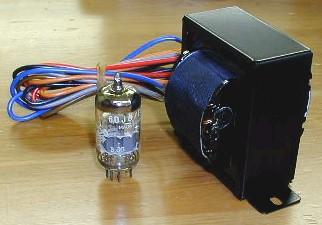
Just tried out a pair of push-pull output transformers on the output. These guys: They're 8k CT : 16/8/4 rated for 15W/80mA on a core just a bit larger than the SRD-7 stepups, but only have a primary inductance of 11H or so. I was expecting the bass to suck, but the SR-X is happily (?) driving a pair of KEF LS50s now. Might mount them to the box and add an output selector.
-
It works! I haven't put it on the bench yet but channel balance seems good. The difference in sound is much greater than I expected, going off of memory. A few interesting side effects of opening the feedback loop: the amp is now a fair bit more microphonic than I recall, and the heater noise is much more noticeable. I ended up elevating the heaters about 30V above the cathode potential, and it's now very very quiet. The bass also seems a bit weaker, I think because the coupling caps aren't in the feedback loop. I'll probably replace them with these.
-
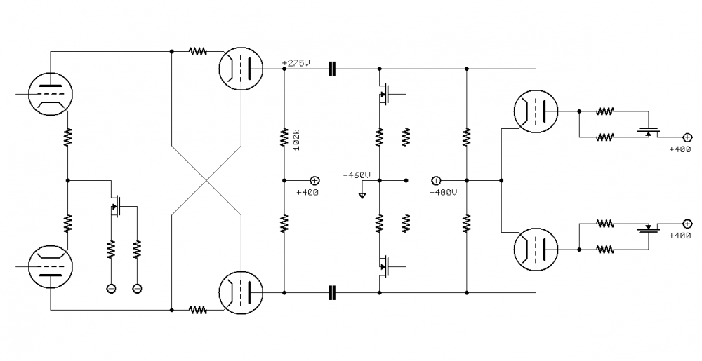
I ended up opening mine to fix a ground loop, and well, one thing led to another until it morphed into this. The outputs are EL34 triodes. Mine never had the tail CCS in the output stage, but rather a shared cathode resistor as well as a C- supply, per this fellow's post over yonder. The old arangement had a C- supply as well as the common cathode resistor that worked quite well. The SR-X Plus' tail CCS seemed like a smart improvement, but wasn't really as practical to implement in my old point to point build. Another alternative was fixed bias. I don't think that gain mismatch between the EL34s would actually be an issue; due to the CCS loading, both plates end up in series with each other through the load. There's a single current loop like in the CCS-loaded LTP. The grid is biased by a LND150 CCS into the grid resistor. The grids sit around -440V, which conveniently means that the output will clip into the rails before drawing any grid current. The plate CCS makes this arrangement quite safe-- at worst, the plate voltage might drift, but the tube shouldn't burn up. I was curious to try the amp without global NFB, so that went next. Considering that a gain of 40 or so is sufficient to drive the output to clipping, I reduced the cascode's plate loads to 100K, which had a few interesting consequences. The lower output impedance is more suitable for driving the EL34's Miller capacitance, which, as JimL said, is a pretty big deal when running without NFB. The 12AT7s are also now idling at 1.25mA per section, and have greater voltage across them. 275V still gives the cascode plenty of headroom. It's still waiting for a -460V supply, which i should finish up tomorrow. Next step is to add some output transformers, and try it on speakers.
-
goldenreference low voltage power supply
PretentiousFood replied to kevin gilmore's topic in Do It Yourself
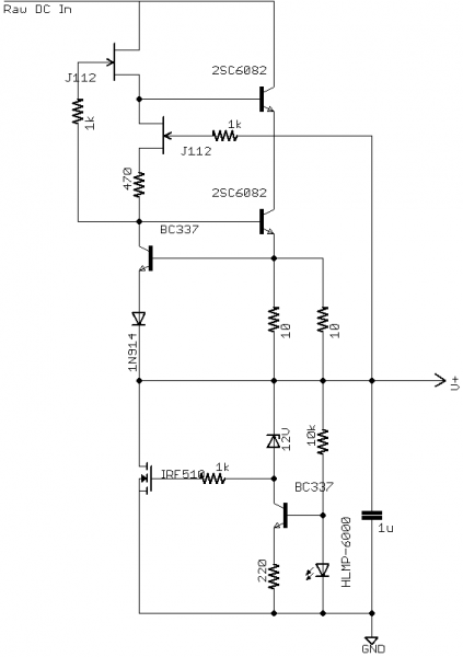
Not with depletion mode parts, but with enhancement mode devices it works quite well. Here's something I'm using for a phono supply at 200mA or so, but it works well at higher currents with a different biasing scheme. You could use a mosfet cascode CCS (like Gary Pimm's) and feedback to the shunt device for better noise rejection, too. -
There is a lot that's wrong with this picture, but, somehow, it sounds pretty nice. JimL, you were right-- it's a G707. The cart is a Nagatron 360CE which I suspect is past its best before date.
-
Appreciate the tip, JimL! Now I won't feel bad if I actually like it.
-
Sound advice. It should get here later this week, will report back!
-
Just picked up a Rega Planar 3 as my first table for what seems like a good price (the Pro-ject Carbon is ~$550 here), but I'm a bit nervous about the tonearm/cart-- it's a Grace, maybe 747? Here's the original classified. Anyone know if the tonearm is any good? For whatever it's worth, it seems to be a pretty common "upgrade." The stylus is in dubious condition, so I may replace the cart if it isn't anything special. I'll be recabling it to balanced.
-
I've used the new-ish Wima DC link stuff (MKP5) to good effect. I think 100uF was $40 or so, and they're available in 1kV ratings. 340uF is closer to $100. Vishay and Panasonic have some really nice stacked film ones for closer to $25 for 1300V, but only up to 40uF. Put the cheap one in a capacitance multiplier.
-
Funny story. I'm using Philips JAN 12AT7s, and hadn't really given it much thought. I'd read here and there that many of the JANs being sold were in fact rejects, so, for fun, I popped them into the tester and came across this gem: Interestingly, the lower current section actually matches the datasheet, so it's definitely not a consequence of aging. The dashed section has about twice the rated gm; clearly, the circuit is very good at forcing AC balance. I'm getting current production, next time.
-
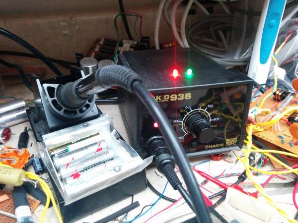
Damaged in an embarrassing way is all I know for sure. I think he was soldering a live circuit, and it shorted through the iron. I haven't used it, but he says the temperature has been unreliable since. It's also certainly no longer under warranty-- he modded it to install LEDs, so that he wouldn't forget to turn it off. (The dead batteries are to keep the sponge moist.)
-
Any recommendations for a nicer soldering station that's not quite as pricy as the Oki stuff? My damaged his Hakko 936, and his birthday is coming up.
-
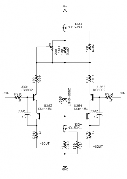
Neat, I like discrete servos a lot! I'd try injecting on the balance current sources as well. I used this differential discrete servo in a single stage pentode amp, which sensed the plate voltage and injected on the screen grid. It could get both plates within 10 or so uV, if I recall. The output needs to be loaded with big resistors (this one worked into 150K). Quiescent output voltage is defined by the tail CCS current minus the second CCS's current (which biases the LM4040), divided by two. Current is shifted from one side of the long tail pair to the other as a DC unbalance appears on the input nodes, until the voltage unbalance is nulled. Could work well as a high impedance reference for the input stage's current sources. It might also work on the plate CCSs if enhancement mode mosfets were used to load the plate- not sure how well it works with depletion mode devices.
-
I made a pretentious food Fried capers on the top.
-

Output Stage Current Requirements for Electrostatic Headphone Amps
PretentiousFood replied to JimL's topic in Do It Yourself
Neat! Thanks for taking the time to explain. I've been nervous about how cold most gain stages were biased for the same reasons-- they do need to drive the Miller capacitance, as you pointed out in the other thread. Looks like it's less of an issue than anticipated, especially when it's wrapped in a feedback loop. -

Output Stage Current Requirements for Electrostatic Headphone Amps
PretentiousFood replied to JimL's topic in Do It Yourself
I'm having a bit of trouble following your calculations. Could you elaborate on how you got the current requirement from the slew rate and capacitance? I've ususally seen the current requirement calculated based on the bandwidth and voltage swing. Morgan Jones has a short section on it in his chapter on preamps. For Stax, it would work out to something like this: Zc = (jCw)^-1 Zc = (j 120*10^-12F 2*pi*20000Hz)^-1 Zc = 50K j^-1 Knowing the plate load, we could then draw a dynamic loadline. Regardless of the load, the transducers' worst-case current draw can be calculated by Ohm's law. I = V R^-1 I = 800Vpp / 50000 I = 16mApp This would mean that the combined signal current of the output stage to drive a 120pF load to 800V would be about 16mA, if it were to remain strictly class A. I think the slew rate would also need to be greater. 800V at 20kHz works out to about 100V/us. I might have an extra zero in there somewhere.


