JimL
-
Posts
641 -
Joined
-
Last visited
Content Type
Profiles
Forums
Events
Everything posted by JimL
-
The SRX input IS a cascoded LTP, AKA Hedge circuit, with cross-coupling per D.R. Birt's article "Self-Balancing Push-Pull Circuits" June 1960 in Wireless World to improve balance for a single-ended input. The T2 also has cascoded LTP/diff amp input but CCS tail and plate loads but w/o cross-coupling. If it's a variation on the SRX, so much for "...a completely clean sheet, creating an all-valve, zero feedback, fully differential design with a direct coupled output stage." A limitation of the SRX input circuit is its high output impedance, which into the Miller capacitance of the output stage rolls off the open loop frequency response above 11 kHz, requiring feedback to flatten the response.. And, plate resistor outputs is so last century.
-
Actually, I wouldn't be surprised if KG amps are vanishingly rare everywhere. As you note, third party amps are a fraction of the Stax market (IIRC, BHSEs are up in the mid-200s), and DIY amps are probably a fraction of that.
-
Agree with spritzer. Now the original 6SN7 is the octal equivalent of the 6CG7/6FQ7 in the SRX Plus, but with only 4 tubes, they are pretty much limited to the Egmont topology, especially since they had both single-ended and balanced inputs. In fact, Jason Stoddard says, "It’s not a unique design—you’ll also see stuff like this also from John Broskie," Here is Broskie's stat amp. You will see it is very similar to the Egmont posted above, with a wrinkle - specifically, the resistor/cap combo in the input diff amp tail to do some Aikido style power supply noise cancellation. If Schiit was running the power supply at +/-400 volts I hope they were using the A/B variant of the 6SN7 tubes as that is over the rated voltage of the 6SN7. Note that the SRX Plus uses 6SN7GTA/B (max static plate voltage 450 volts, max power dissipation 7.5 watts combined) which increases the voltage and power limits a bit over the 6CG7 (max plate voltage 330 volts, max power dissipation 5.7 watts combined) in the original SRX, or the 5965 (max plate voltage 300 volts, max power dissipation 4.0 watts combined) in Broskie's design. Using the A/B variant of the 6SN7 in combination with the constant current sources gets the circuit off its knees in terms of drive capability, although it is not nearly as capable as the top Gilmore designs in ultimate drive capacity. Incidentally, if anyone is concerned with running 6SN7GTA/B tubes at 320-350 volts static plate voltage, RCA has plate curves running up to 650 volts plate voltage. 400 volts on the other hand may be pushing things a bit.

-
Nice to have the SRX-P included in the group. Of course, you can roll different 12AT7 and 6SN7GTB in that too, which may change the flavor a bit. I like the Sylvania GTAs myself.
-
I assume the Stax were better built too - somehow, the Kingsound looks like it's made from recycled tin cans.
-
IIRC the basic circuit is the SRX, which is fine. Mikhail just did everything he could think of to f**k it up.
-
Whoa! I thought you had already re-built it. Are you going with constant current output loads, or sticking with the resistor loads?
-
Yeah, basically the same circuit, the only thing that changes is the outputs - transistor vs tube, resistor load vs constant current load...
-
Possibly a very high impedance coating? The original Quad ESL had an extremely high impedance coating and hence took a while to charge up.
-
Speaking of which...what capacitance are those PS caps in the T8000? When I refurbished my T1 I substituted 330 uf/450V caps for the original 100 uf ones. Dunno if it made a difference but it couldn't hurt.
-
Q27 and Q30 have base and collector connected together and so behave like diodes and in series with the LEDs D2 and D3, provide a constant voltage for the constant current sources Q26, Q28 and Q29. I believe that Q18-21 form a modified Vbe multiplier - this part of the circuit is not new - the exact same topology is seen in the T1, 600 and 727, among others. The circuitry around Q31-33 is a voltage regulator to stabilize the voltage to the tubes and intermediate stage. I'm sure KG will come along and correct me if necessary.
-
Cool, looking forward to the full schematic. PS looks like 78/79 front end regulation (the two heatsinks) and for the extra slot, but R-C high voltage?
-
Actually, that's just a Cockroft-Walton generator/voltage multiplier. Same principle as the voltage multiplier in the Stax bias supplies, except MUCH higher voltages, e.g. 1-3 megavolts out, albeit with a fair amount of ripple. Walton and Cockroft used it to accelerate charged nuclei to bombard atoms and transmute them into heavier elements, for which they won a Nobel Prize in physics. Currently, used to give charged particles a starting kick before they enter the circlotron.
-
DIY tube phono stage, a variation on a JC Morrison design. Published in AudioXpress in 2004.
-
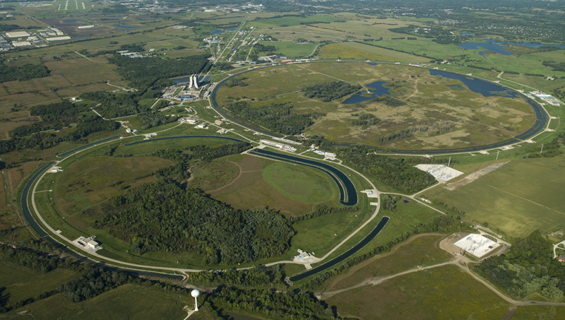
You call that a circlotron? HA! THIS is a circlotron: The Fermilab in Batavia, IL. 2 miles in circumference. Too big for my house. The CERN Large Hadron collider, see above, is more recent, and even bigger - 27 km circumference.
-
Cool!
-
Oh, cool! Cascoded pentodes would work really well. Lots of heat, lots of filament supplies.
-
The prototypes have been demonstrated at several shows in the past couple years, not sure they are on the market yet.
-
Thanks, spritzer. The article is already published but I can ask them to put in an addendum adding the 5M resistors to the bias supplies. I haven't seen the first gen T1 either (other than a photo on the internet) but the mods only concern the output stage so I think they should work equally well.
-
To put it another way, compared to the Stax Mafia, this is like Stax juvenile delinquency.
-
You're right about the LV supply (Stax did stick in some zener diodes to sort of regulate it), but this was meant to be a simple mod. It is intended to be bang for buck, and the most significant improvement is the constant current mod. Yes the power supply could be much better, but the constant current mod is a first order improvement, the power supply is a second order improvement. The intended audience wasn't the Stax Mafia, it was people who have a Stax amp and want to improve it without going to the expense of a KGST level amp. Or are just getting into Stax and are willing to do a little DIY (or have it done for them). I think more people would be interested in Stax if they could buy a $500 used amp, put $100 and a few hours work into it for some significant improvements, instead of spending a few thousand for the amp. Not everyone is interested in building from scratch. Actually, I didn't comment on the bias supply as I was not aware that was an issue, but now that I look at the schematic, I see that there should be a 5 megohm resistor after the last capacitor for protection. Damn!
-
When you're going downhill, you pick up speed.
-
That's precisely the idea. It doesn't quite get to the KGST level, but it's not far behind.
-
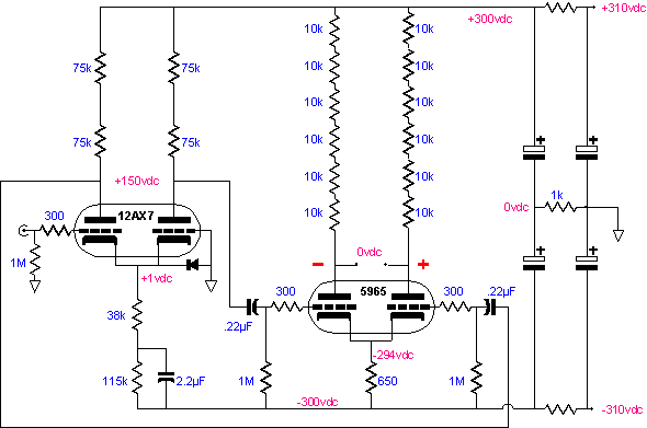
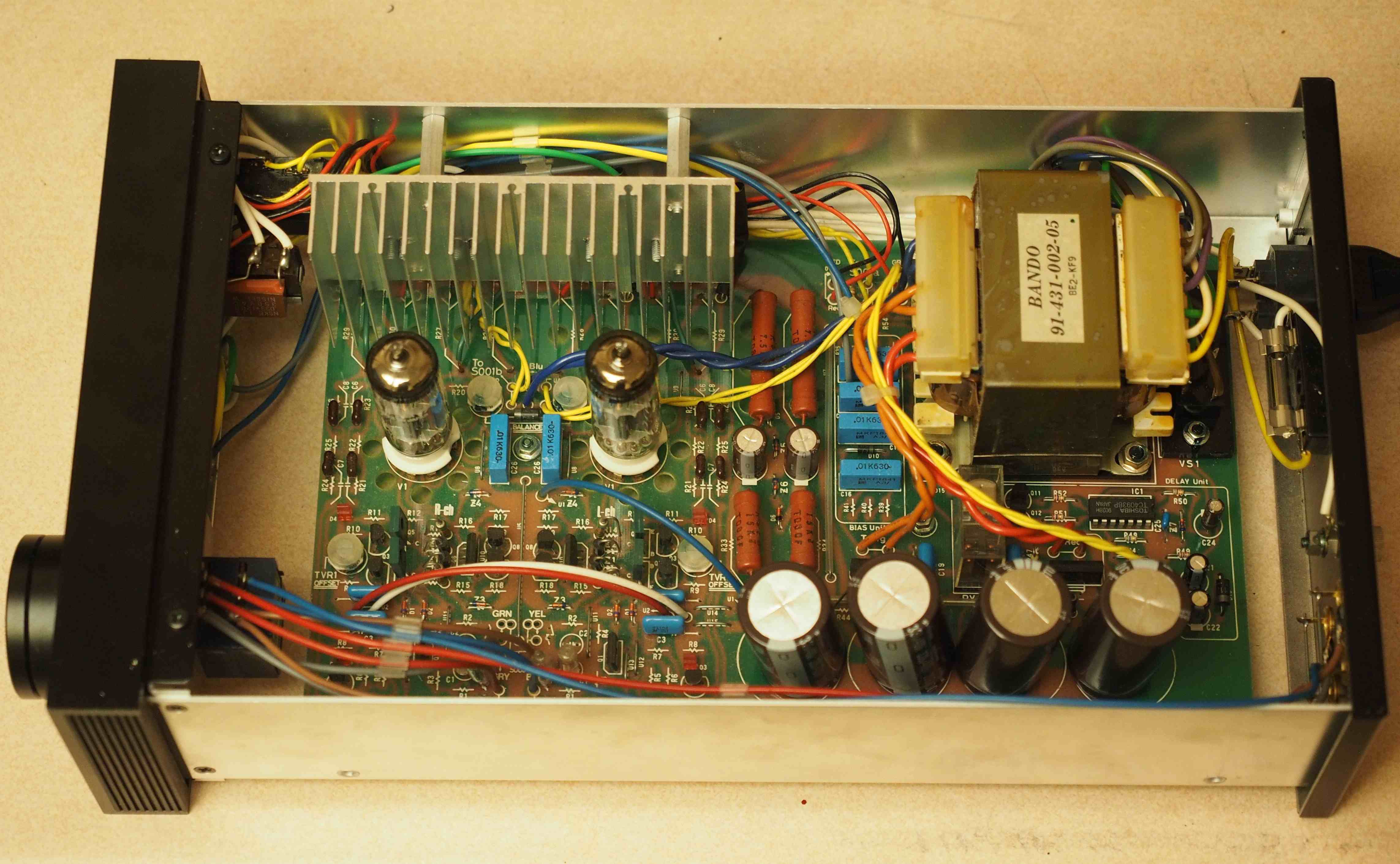
I published a modification for the Stax SRM-T1/T1S/006 in AudioXpress July 2017, which is just out. The modification adds 5.1 kilohm output safety resistors and cascoded constant current output loads, which with their heatsink fits the space vacated by the plate resistors - see photo. Spritzer did something similar a few years ago with an SRM-007, adding constant current loads, but he also changed to 6S4A outputs. Unlike plate resistors, constant current loads burn up practically no signal current, so while the stock amp burns up 9.2 mA signal current in the plate and feedback resistors at its specified 300 VRMS maximum output, the modified amplifier only uses 2.8 mA driving the feedback resistors, leaving much more current available to drive the headphones. Since the output tubes are much less stressed, distortion is decreased and 2 dB of extra headroom gained. The modified amp circuit is very similar to a KGST or KGDT. This is no accident, as the KGST was designed to be “a Stax SRM-007t with no cost or retail considerations,” and the 007t is a higher power T1. The modification lacks the KGST’s regulated power supply, but larger power supply caps have been fitted. Since the amplifier is fully differential pure class A with current sources or loads at every stage, the current draw is pretty constant, minimizing power supply effects. The modified T1 can drive demanding headphones like the SR-007 Mk I, something that the stock design strains to do. The relatively flabby bass, somewhat dark tonality and soft treble are largely eliminated. Replacing all the old electrolytic power supply caps should also be done as routine maintenance. Parts cost for the modification is about $35, so total parts cost is around $100. With T1 amplifiers going for $400-$700, this is the best bang for the buck, a good starter project for someone wanting to get into electrostatic amp DIY without going to a full build.
- 37 replies
-
- 14
-

-

-
Just looked, actually both the Utopia and LCD-4 are on the Wall of Fame, which is what Tyll said he was going to do on his blog of June 9, "I will be leaving the Utopia on the WoF, and will add the LCD-4 to the Wall of Fame, though reservedly."