JimL
-
Posts
641 -
Joined
-
Last visited
Content Type
Profiles
Forums
Events
Everything posted by JimL
-
1000vct is somewhat high for a choke input supply. Remember the higher the raw voltage the more you have to burn up in the regulator. For +/-350 volts regulated, you want to have around +/-370 volts raw PS output at your minimum brown-out voltage. If the brown-out is 10% low, then that works out to 410 volts raw supply out at a nominal voltage (e.g. 120 volts US, 240 volts EU, 100 volts Japan). Figure another 10% losses in the choke, etc. and that works out to about 900 vct at 50 mA or better. Now if you use the KGBH supply which is cap input, then divide that by 1.4 to give around 640 vct, but you should also go with around 100 mA current or more. Those should give you an idea of the transformer size.
-
Dr Gilmore designed a board for the amp, I'm trying to design a board for the PSU.
-
You HAVE to have two 6.3 volt windings because the 6SN7GTA cathode sits at around -320 volts and the 12AT7 cathodes sit at around 0 volts and above. You cannot get away with one 6.3 volt winding, due to exceeding the filament-cathode ratings resulting in premature tube failure. This is one of the screw-ups in the SinglePower ES-1.
-
So, I thought I had finished the PCB design, but there were a couple missing holes, and then the more I tried to correct things the worse it got, so I don't have working Gerber files at present. GRRRR! I'm traveling today, so will try again tonight. If worst comes to worst, may have to start from the beginning. Part of the problem is that I tried to incorporate a ground plane into the PCB, then have the mounting holes connect to the ground plane.
-
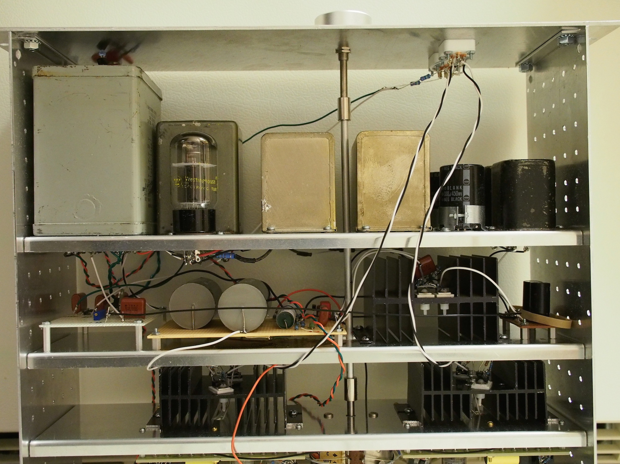
You don't really need a 5v tap, I just used it to power the delay circuit. You do need two 6.3 volt windings (on KG's board he actually uses a 6.3 for the 6SN7GTA/B and 12 volt windings for the 12AT7s, so be aware of that. So the two gray boxes on the left are transformers (the smaller one is actually for the rectifier tube. The other boxes in the middle and right are chokes. You can substitute a solid state bridge rectifier for my hybrid rectifier, and you can eliminate the second pair of chokes. The basic KGBH supply will work also, just set it for +/-350 volts.
-
I just did the gerber files for my PS. Also have a schematic but this is all in KiCAD, so not sure how to proceed from here. The PS supply is the same as the schematic in the SRX revised thread except for the addition of an 0.1 uf/1000v cap on the input side between B+ and B-. The PS does not include the bias supply but I used KG's design anyway and I believe that is available as a separate board.
-
Most of the resistors are 1/2 watt, although I used 1/4 watt for the current source resistors. The 220k resistor chain in the output stage uses 2 watt/500 volt resistors, and I used 1 watt/500 volt resistors for the 5.1k output safety resistors. As for the .22 uf/1000v caps, I think the board is designed for rectangular caps. I built mine point-to-point and I used 0.1 uf/630 volt axial caps. Basically whatever fits. I think a 2 mm board is good. It's not that the tubes weigh that much but pushing them into the sockets will take some force.
-
As a matter of fact, MLA, your memory is fine. The original publication date was indeed October, and it did get pushed back a month.
-
Hi, My modem died last week so I'm just getting back on the net and saw this thread. A couple corrections. The articles are in the November and December 2015 issues of AudioXpress. The original SRX circuit is indeed quite spare: 3 tubes, 1 trimmer, 4 caps and 13 resistors per channel. The SRX Plus is more complex: 3 tubes, 8 MOSFETS, 5 trimmers, 4 caps and 35 resistors, but I think the performance takes a substantial jump. See the SRX revised thread and also the Current Requirements in Electrostatic Headphone amplifiers elsewhere in the DIY section for all the gory technical rationale. I am also in the final stages of working up a PCB for the shunt regulator PS. It includes input caps but not the rectifiers, as I intend it to be used with either a cap input (in which case you just need the transformer and full bridge rectifier, or choke input (in which case you need two chokes also), which would be mounted off board. It's a slow process since I am learning to use KiCAD while I'm also doing the board. I've lost count of the number of times I've used Exit without Save when I've screwed up and had to go back to an earlier iteration. I still have to figure out how to do the mounting screw holes and the component mask layer. Currently the board measures about 6.5" x 3.75" and one edge is intended to attach to a heatsink so it won't blow up if all the current has to run through the shunt. BTW if there is a group buy I would be interested in a board.
-
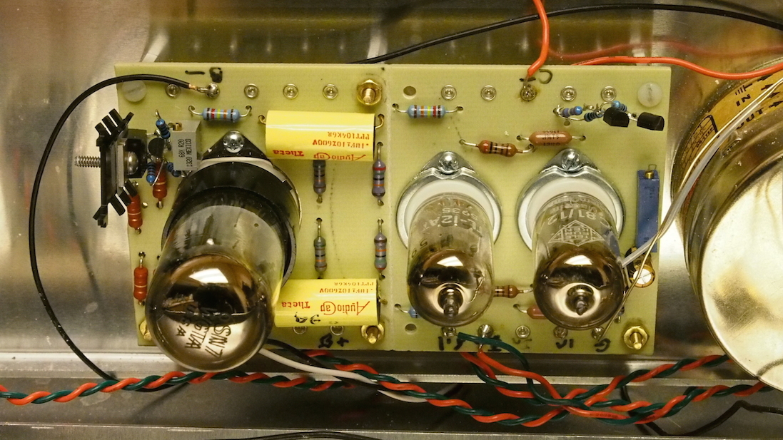
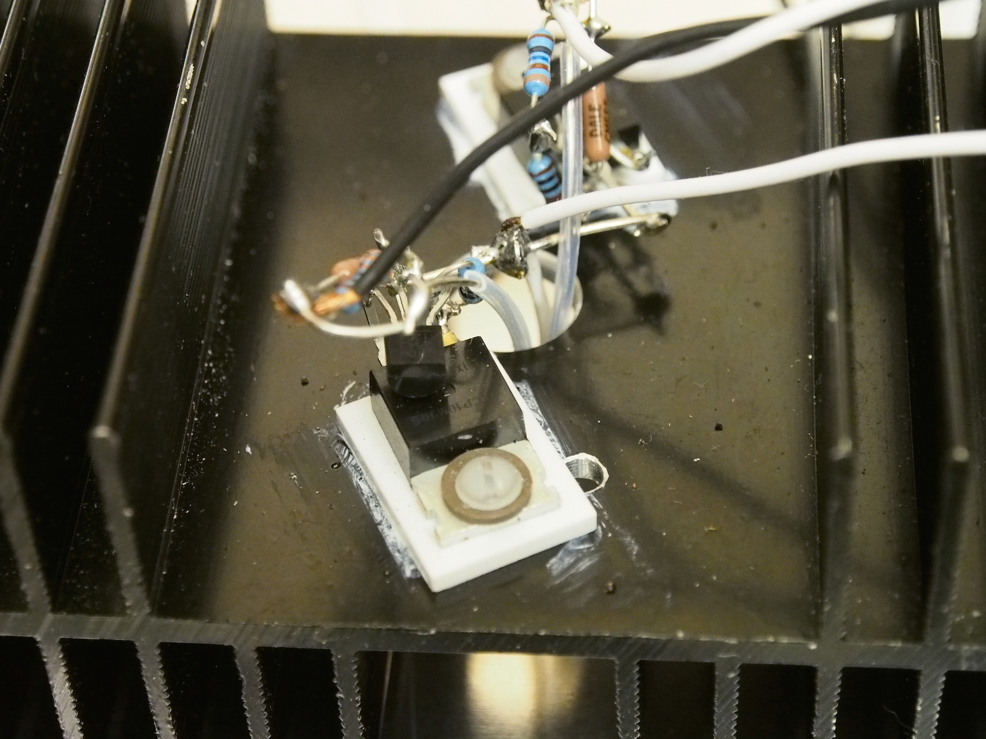
Here is the board layout for one channel, wired point-to-point. It's pretty straightforward, signal flow from right to left with input on the right and output on the left. The other pic shows the output current load heat sinks - the wiring goes through the supporting shelf to the current load heatsinks bolted to the other side of the shelf. Other layouts are possible of course. The small heatsink on the left is for the output stage current sink, and is a bit marginal - a bigger heatsink would be better. Everything is soldered together which is good for electrical connectivity but not so good for repairs, but I was building it for myself rather than a commercial design where ability to make repairs easily is an important concern.

-
One clarification on my last post, the Speaker Builder issue that I published my article in was the 6th issue of 1989, corresponding to Nov/Dec. luvdunhill, I'd be happy to take a look at the schematic. If it's that complex, I assume you have electronic bits scattered all through it. I assume you checked the offset in the interim electronic bits?
-
I published the design for this subwoofer in Speaker Builder 6/89. Briefly, the Hartley has a Qts = 1.3 and Fs = 28 Hz. The baffle is calculated to roll-off below 100 Hz or so, but because of the boost with the Qts = 1.3 (maximally flat being Q = 0.7), the EQ boost starts at 80 Hz, rising down to 20 Hz, which gives a relatively flat overall response down to 28 Hz. I also put in a 12 dB/octave roll-off below 14 Hz. For the last few years I have also used a Symmetrix parametric equalizer with an Infinity R.A.B.O.S kit to get a frequency response of +/- 2 dB between 20 and 60 Hz. For the bass crossover I used a 24 dB/octave Linkwitz-Riley roll-off above 60 Hz, using TL075 and 4136 quad op amps. For the Quads I used a 6 dB/octave passive RC filter at 60 Hz, which in combination with the 18 dB roll-off of the Quads gives roughly a Linkwitz-Riley 24/octave crossover.
-
So many Stax DIY Amplifiers, which to choose?
JimL replied to Juggernaut1101's topic in Do It Yourself
Just thought I'd mention that AudioXpress has published both parts of my SRX Plus article, and I've completed the discussion of its design in the SRX revisited thread. Dr. Gilmore has board files on the amplifier. One of these days when I've got the time I might design a board for the power supply but it's simple enough to be built point-to-point. -
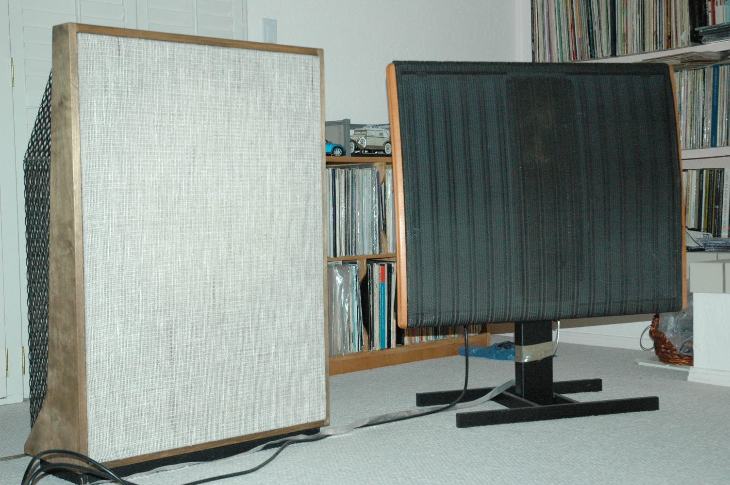
On a slight tangent, here is the dipole subwoofer I use with my Quads. Behind the grill is a Hartley 24" driver.
-
Internal layout for anyone interested.
-
Custom Case?
-
Ok, the hybrid version I was referring to in the last post was an early version using the TL431 chip. I found a schematic of another (later?) version which uses the same cascode diff amp into current mirror voltage regulator circuit (with 2SA1486 and 2sc3381 BJTs) as the HV series regulator, circa 2011, but controlling 80N80C MOSFET shunt. Schematic was also dated 2011.
-
I remember that, in fact I think I printed out a copy of the schematic which is dated 2011. IIRC it was somewhat noisier than the series reg using the LM-4040, which is noisier than the current Golden Ref HV. I think the other issue was that an early version that tried to shut off the current had large oscillations - hundreds of volts IIRC. Of course, I'm not trying to outdo the Golden Ref HV, which is significantly more complex than my simple supply, I just wanted to have a good, inexpensive shunt PS, as I am a cheapskate at heart.
-
I don't know that they need to compare with a T2/009, how about a BHSE/007 or KGSS Carbon/007?
-
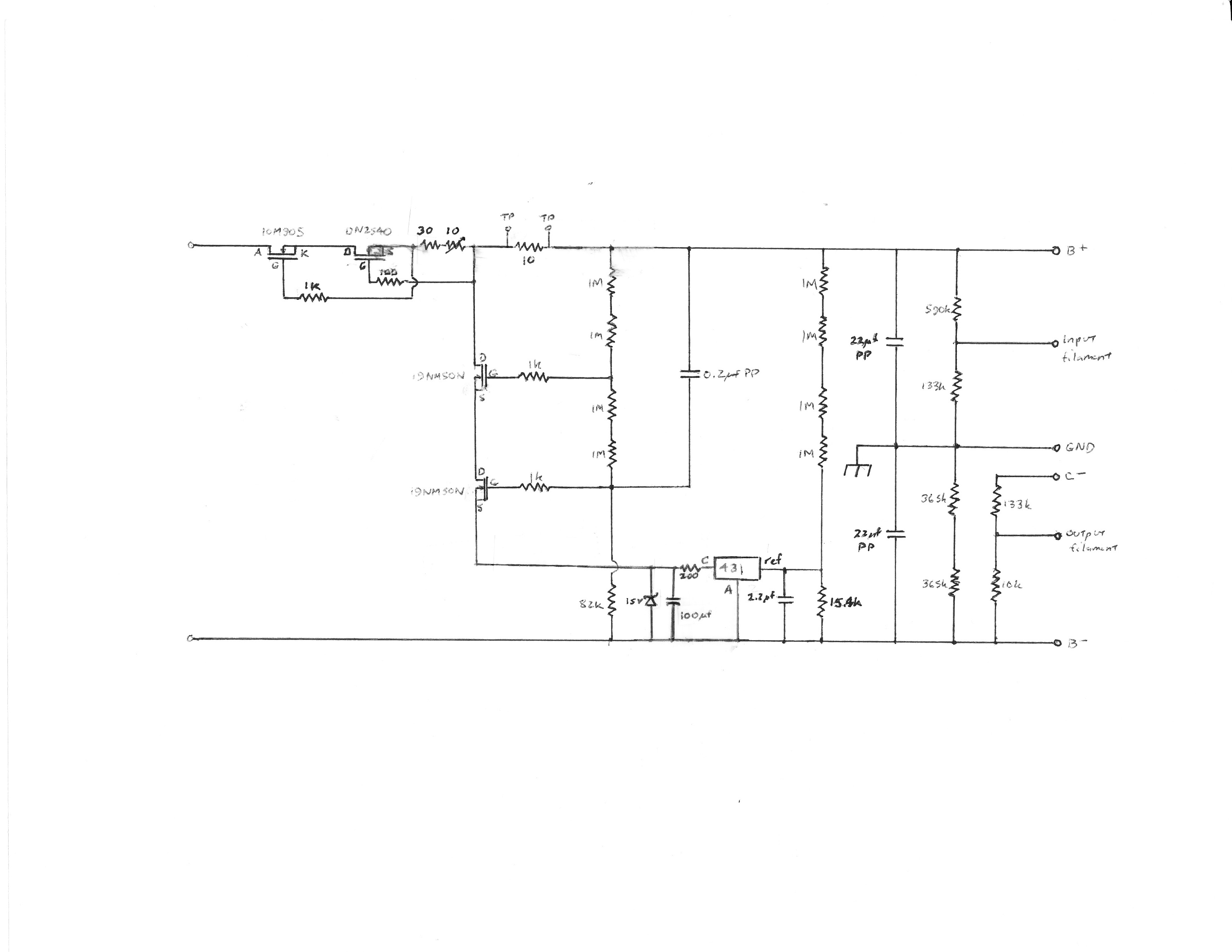
The second part of my SRX Plus article is now published in the Dec 2015 issue of AudioXpress so I can complete the discussion of the shunt power supply. The schematic is posted above. It is almost deceptively simple, but with some neat design touches. There are dropping resistors for the input stage tail current source, resistors to set the voltages across the output capacitor, and taps to bias the filament voltages for the input and output tubes. The regulator tube in the July 1999 TubeCAD circuit is replaced by two cascoded MOSFETs. Since MOSFETs have a much higher transconductance than any triode, this significantly improves its performance with minimal additional complexity. It uses an Exar SPX431 IC shunt regulator, a temperature compensated chip with about 10 dB lower noise compared to the basic TL431, specified to sink up to 100 mA at a maximum of 30 volts – though not simultaneously, since its maximum power dissipation is 775 mW. The noise specification appears comparable to the LT1021-10. Kevin Gilmore and Linear tried to design a shunt regulator using the 431 back in 2011, however they abandoned it because of oscillation/stability problems and noise issues. In basic form it had a tendency to oscillate, but stabilizing the IC against oscillation slowed down its response significantly, making it an ineffective AC regulator. Broskie’s design addresses this problem by bypassing it – literally. In so doing, he converts the liability that KG and Linear were plagued with into a benefit, although that was not his primary intent. Sometimes, you get lucky. The raw B+ goes into a cascode constant current source (CCS) like those in the SRX Plus circuit. The total current is set by the fixed resistor and trimmer pot on the DN2540 source leg. The circuit appears to be asymmetric, but the CCS forces any current variations caused by the amp to be exactly compensated in the regulator so that the total current remains constant, and thus the current in the negative leg must also remain constant. If the amp load disappears, 40+ mA goes through the regulator, resulting in more than 30 watts dissipation. A Wakefield 421K heatsink or bigger should provide sufficient heatsinking, at least for a while. All active devices except the SPX431 are mounted on the heatsink. An adequate heatsink is very important, particularly if you use an all solid state bridge rectifier, because in that case, the power supply voltages rise to their final values almost immediately. However, since the amp circuit does not start drawing current until the tubes warm up, for 10-15 seconds all of the power supply current runs through the shunt. The shunt element is two cascoded high transconductance STP19NM50N MOSFETs buffering the high voltage to the 431 IC, with a resistor string setting their quiescent voltages and a zener protecting the 431 from overvoltages. A second resistor string for the 431 reference terminal sets the DC voltage, while the 2.2 µf capacitor between the reference terminal and B- bypasses audio frequencies above 5 Hz, limiting its function to setting the DC voltage. Broskied did this primarily so the shunt tube would perform the AC regulating function rather than the IC – but as a side benefit, stabilizing the IC will not affect the regulator’s AC performance. The 200 ohm/100 µf RC network between the 431 anode and cathode stabilizes the IC against oscillation, provides a measurement point for the static shunt current, and filters the 431’s output noise above 8 Hz. The RC filter was suggested in a note by John Curl. This network slows the response of the 431 considerably, but that is actually a benefit as it further restricts its AC activity. Should the output load disappear, the additional current through the resistor drops the voltage across the IC, limiting its dissipation to a safe level, but leaving the regulator on. Accomplishing four functions with two components is elegantly simple. As Broskie notes, separating the DC and AC functions limits the sonic effect of the mediocre op amp in the SPX431, while using it to do what it does best, setting a stable DC voltage. B+ noise and signal variations are fed by a 0.20 µf capacitor into the gate of the lower MOSFET, which acts as a fast AC shunt regulator. Since this MOSFET’s source sees B- noise and signal variations via the 100 µf capacitor, any changes between B+ and B- will alter its gate-to-source voltage, and hence the current flow through the shunt, to maintain regulation. It is generally considered desirable for the power supply frequency response to be greater than the amp circuitry. MOSFETs can respond well into the MHz range, hence the gate stopper resistors to prevent oscillations. Cascoding the MOSFETs preserves the transconductance of the lower MOSFET, minimizing its AC resistance. Hold on a minute, doesn’t a cascode have a high output impedance? Yes – but it also has a high gain. The regulator circuit has 100% feedback so the overall gain is -1. With feedback, the output impedance of the shunt is roughly the on-resistance of the lower device. Broskie notes that this design provides a single simple pathway, a virtual AC short, between B+ and B-. Since the B+ and B- are set by the resistor dividers, they track each other, and since the power supply ground is not directly involved in the regulation, interaction between power supply and audio signal grounds is reduced. By contrast, in the usual bipolar regulated supply, B+ and B- are regulated separately with respect to ground, the two supplies do not track each other, and the regulating currents flow through the power supply ground – a less optimum topology. Small circuit modifications improved performance significantly. The regulator was wired point-to-point on perfboard, making modifications easy to implement. Initially, I used a TL431 with its cathode connected to the lower MOSFET source by a 100 ohm resistor, and a 10 µf cap between its anode and cathode, similar to the TubeCAD circuit. With this, the amplifier output noise, measured with a Fluke 189 DMM with an AC bandwidth of 100 kHz, was about 200 mV RMS with the input grounded. Changing the 10 µf capacitor to a 2 ohm/10 µf RC stabilizing network across the 431, as suggested in Texas Instruments’ application note, the amp output noise decreased to around 50 mV RMS, suggesting that much of the previously measured “noise” was actually ultrasonic oscillations. In this configuration, the regulator noise measured about 5 mV RMS between B+ and B-. Finally, changing the RC network to 200 ohms/100 µf, connecting the MOSFET source to the RC junction, and substituting the SPX431 reduced the regulator noise to <2 mV RMS. More significantly, the broadband amp output noise dropped to 3-5 mV RMS. By comparison, earlier this year, Kerry measured the newest version KGSSHV power supply noise at around 5 mV RMS, so in real world terms this shunt PS appears to be in the same ballpark or better, although in fairness, NYC is probably an electrically noisier environment than New Mexico. This is excellent performance for such a simple circuit, although it probably helps that the raw power supply is pretty quiet. Voltage was very stable, varying by about 0.1 volt (<0.02%) from cold turn-on to fully warmed up, which is also excellent. The headroom between the raw power supply and the regulated voltage was about 20 volts – this with a 780 VCT transformer. My system has a line voltage regulator so this is adequate. Most systems will need around 100 volts headroom to prevent the regulator from dropping out under brown-out conditions, so an 850 VCT transformer is recommended. This regulator is simple, quiet and stable, but not the lowest impedance, the major limitation of this circuit. The 431 is only reacting to a small proportion of the overall voltage, so the DC impedance is around 40-60 ohms, but since the amplifier has a constant current draw this is not a significant issue. At audio frequencies and above, the dynamic impedance is determined by the on-resistance of the 19NM50N, which is specified at <0.25 ohms, although it probably somewhat higher at its low designed shunt current. At the highest audio frequencies and above, the metallized polypropylene output capacitors contribute to lowering the dynamic impedance. However, the amplifier circuit presents a very high impedance to the power supply, so this still looks pretty close to an ideal voltage source. The benefit of a more complex, lower impedance power supply circuit is likely to be subtle. The optimum shunt current for a regulator is somewhat controversial. Allen Wright stated that the current through the shunt should be at least as great as the current drawn by the active circuits, doubling the power consumption. Broskie maintained that enough current to provide a few mA over the maximum current draw by the amp is sufficient, and Kevin Carter reported that increasing the shunt current of beyond the minimum necessary to maintain regulation for differential amplifier circuits decreased audio quality. In nearly all amplifiers, most of the current variation occurs in the output stage, but the output stage in the SRX Plus is isolated by current sources and sinks, so its current is invariant. This leaves only the input diff amps - a few extra mA in the regulator beyond the requirements of the active circuit will satisfy all criteria. The shunt current can be determined by measuring the voltage across the 200 ohm resistor in the RC network – each mA will produce 0.2 volts across it. The normal power dissipation in the regulator is about 5-6 watts, and the power supply heat sink runs about 45o C fully warmed up. In conclusion, the SRX Plus is a fully differential electrostatic headphone amplifier with shunt regulated power supply, which works equally well balanced or unbalanced, is inexpensive and easy to build, and uses no esoteric parts. The design is spare and economical, yet high performance. The highly effective current sources in the output stage allow the modest output tube to punch well above its weight class. See the thread on output current requirements in electrostatic headphone amplifiers for a more detailed discussion. With a +/-350 volt power supply, it will closely match the output of the original KGSS. While it lacks the sheer overkill speed and power of the state of the art amplifiers, I am reminded of what Rolls Royce reportedly replied when a customer asked how many horsepower their engine had, “Sufficient.” That’s the SRX Plus – sufficient. So I you have a KGSSHV, KGSS Carbon, Megatron, BHSE or DIY T2, why would you want to build a SRX Plus? Two possible reasons: First, to see how cheap and easy you can go and still get really good sound. Second, to see how contemporary tube technology sounds. I say tube technology rather than hybrid because the tubes do all the audio signal handling. What solid state is there is current sources, which do minimal audio handling (if they were perfect, i.e. infinite resistance, they would only provide pure DC and not one signal electron would enter or leave the current source) and the power supply, which mostly provides DC. When I started in audio, I was a member of the Boston Audio Society, which an audiophile magazine once sneered, “wants audio nirvana for $79.95.” Yep, that’s me. I’m not really a Stereophile Class A type guy, I go for class B: “close to the best for a reasonable price.” IMHO the SRX Plus fits that description perfectly.
-
No kit, if you want to get a PCB you'll have to get the board files from Dr. Gilmore's site, send them to a board maker and have them made yourself, unless you get in on a group buy.
-
The first part of my SRX Plus article is out in the November issue of AudioXpress. Part 1 covers the amplifier circuit, although due to word count limitations, it is not as detailed as the discussion already posted here. While waiting for Part 2, which covers the regulated power supply and should come out in mid-November, let me discuss some general issues related to active power supplies. With a quiet, stable raw power supply, do we really need power supply regulation? Some audiophiles prefer passive power supplies to regulated ones, claiming they can hear the negative effects of high feedback in the regulator - some pejorative words that have been used include: mechanical, electronic, artificial, grainy, and coarse. However, regulation can be very useful. An ideal power supply is a fixed voltage source: it can supply any amount of current at any frequency with zero impedance, no noise, hum or ripple. A passive supply cannot do any of these things - a regulated power supply can come significantly closer. First, an active supply provides a stable voltage for the amplifier circuit. The AC power line voltage can vary, particularly in the summer when there is a heavy demand from air conditioning, and the voltage often decreases resulting in “brown out” conditions. In DC coupled amplifiers a variation in the power supply voltage could cause undesirable changes in the DC output. Second, it filters out any residual hum, ripple, spikes and noise from the AC line that gets through the passive supply. Third, it provides a low impedance power supply across the audio spectrum. This stabilizes the operational parameters of the amplifier and reduces interactions due to voltage variations from signal currents drawn by the amplifier, whether these interactions are between different stages in an amplifier, or between channels in a stereo amp with a shared power supply. Of course, it has to do this without adding any significant noise of its own. See Richard Marsh’s article “Power Up” in the 3/83 issue of The Audio Amateur for a fuller discussion. There are two kinds of linear voltage regulators, shunt and series. The simplest shunt regulator is a resistor and zener diode. Shunt regulators are most useful when the current draw only varies over a relatively limited range, since in order to function, they require that some current always be shunted to ground. Thus they work well with class A amplifiers. One feature of a shunt regulated supply is that the current draw from the raw supply is pretty much constant – the total current is divided up between the shunt and the active circuit. As the active circuit draws more current, less runs through the shunt, and vice versa. However, if the load disappears for any reason, all the current goes through the regulator, which can blow up unless it has adequate power dissipation. With a class AB speaker amplifier, the current draw may vary from several milliamps to several amps. A shunt regulator would have to run (waste) several amps all of the time in order to maintain regulation up to the maximum amp draw – very inefficient. In this respect a shunt regulator is like a class A amp. In this situation a series regulator would be far more efficient since it only needs a relatively small current to maintain regulation. With a series regulator, the current draw from the raw supply will vary depending on the power needed, similar to a class AB amplifier. Hence, Broskie‘s comment that shunt regulators match well with Class A amplifiers and series regulators match with class AB amplifiers. Just as Class AB amplifiers are much more common than Class A amplifiers, series regulators have been more common than shunt regulators. Series regulators such as the 78XX/79XX ICs are widely used. There have been several series regulator designs published in The Audio Amateur and AudioXpress over the years by Boak, Sulzer and others, including very high performance, low noise, low voltage designs by Walt Jung that feature output impedances of <0.1 milliohm over much of the audio range. By comparison, a 7915 regulator has an output impedance of around 30 milliohms over the same range, and the resistance of 12” of #18 AWG wire is about 5-6 milliohms. Despite these impressive specifications, a number of designers like Allen Wright (Vacuum State Electronics), Richard Marsh, Lynn Olson (Nutshell High Fidelity), John Camille (Chimera Labs, Bottlehead), John Broskie and Frank Cooter contend that shunt regulated power supplies are sonically superior to series regulators. I am agnostic on that, although come to think of it, I do not recall any designer claiming that series regulators sound better than shunt regulators. The fact that shunt regulators work by varying the shunt current can be an advantage. For an amplifier driving a non-resistive impedance, e.g. an electrostatic headphone, the amplifier will source current into the headphone to generate the voltage across the stators. But then when the voltage goes down that charge will surge back into the amplifier. This charge can flow easily down the shunt, which is already on, leaving the amplifier relatively unperturbed. A series regulator can easily source current but has difficulty sinking it. Marsh, Camille and Wright regarded this ability to both source and sink current symmetrically as a major reason for the superiority of shunt regulators. Marsh suggested pre-loading series regulators to about 50% of maximum load with a resistor. Walt Jung noted “this…allows the series regulator to both source and sink output current, with a sink capability up to the level of the bleed current.” However, this reduces the efficiency advantage of a series regulator since the bleed resistor is constantly wasting energy. Another advantage of shunt regulators that has been cited by Broskie and Camille is that the shunt provides a short, simple, clean current path to ground (or B-). Both felt this was beneficial. Finally, shunt regulators tend to absorb noise rather than transmit it. As the SRX Plus is a class A amplifier, I decided to use a shunt regulator. I wanted it to be high performance, but simple, in keeping with the design of the SRX Plus itself. As noted, shunt regulated amps draw a pretty constant current from the raw power supply. We can reinforce this by using a constant current source in place of the series resistor. This has several advantages. First, it greatly increases the isolation between the raw power supply and the active circuit. A constant current source has a very high AC impedance whereas the shunt regulator has a low AC impedance, so the line rejection ratio is basically the ratio between the impedance of the current source and the impedance of the shunt element. Second, the current source prevents any signal currents from migrating back into the raw power supply, since it forces the regulator current to precisely mirror the current drawn by the active circuit so as to keep the total current invariant. Thus, any signal currents are restricted to the active circuit, the shunt, and the wiring between them, which decreases unwanted cross-couplings. Third, the current source limits the amount of current that can flow through the regulator if the active circuit should blow up. This gives a predictable power dissipation for the regulator in the worst-case scenario. Fourth, the current source only needs a modest voltage drop across it – 15-20 volts is enough. For the constant current source, we can use the same design used in the SRX Plus. Then all that remains is to design the shunt. There are a number of high voltage shunt regulator circuits out there. However, nearly all that I could find were unipolar and limited to 300-600 volts, most commonly to 300-450 volts. Since the SRX Plus needs a bipolar supply of +/-325-350 volts, one would have to use two stacked supplies. Also, many of the designs used IC op amps, requiring a low voltage supply for the IC. The reason for using IC op amps to drive the pass or shunt device, in either series or shunt regulators, is to lower the output impedance by increasing the overall voltage gain, and thus the change in current for a given voltage change. This improves voltage regulation when the amp circuit draws an appreciable signal current, although the additional gain can lead to potential stability issues when combined with the required 100% feedback. However, the SRX Plus has a long tailed phase splitter input stage and a differential output stage. In both these circuits the signal current in one half of the stage is balanced by the signal current in the other half, so that the total current flowing in the stage is pretty much constant, especially when that balance is enforced by the constant current source in the tail. In theory, the amp circuit should not draw any signal current from the power supply. Therefore, the AC output impedance of the power supply becomes less important, and the need for an op amp is lessened. Of course, this also means that the advantage of a shunt regulator being able to sink current becomes largely irrelevant and a series regulator might do about as well. Still, what fun is it, just imitating what everyone else is doing? An ideal shunt element has an AC impedance of zero, or an infinite transconductance. Among active devices, triodes have a transconductance of a few mA/volt, pentodes do better, and MOSFETs even better –an amp/volt or more. Simply put, a single triode shunt element might exhibit a shunt impedance of a couple hundred ohms, whereas a single MOSFET might have a shunt impedance of less than an ohm. Thus, using a MOSFET for the shunt device allows us to achieve a reasonable performance without the need for additional amplifying devices. I found a simple bipolar tubed shunt regulator on Broskie’s TubeCAD website which I chose as the basis for my power supply design.
-
You are correct, there should be a zener diode in there. My guess is that the schematic you posted is in error, the left-most diode should be a zener. In my copy of the SRD-7 Mk II that is precisely where there are back-to-back zeners to limit the voltage.
-
The way it works is that the same transformer that steps up the voltage to drive the headphones also provides high voltage to the bias circuit. The bias circuit drains off a little bit of current from the signal voltage to fill up the bias capacitors. Think of the diodes as being one-way doors for the electrons. Every time the music voltage peaks higher than the voltage that is already on the bias capacitors, some current flows into those capacitors, gradually topping them up. The reason this works is that the bias requires voltage but almost no current, except when you first start up, so draining a bit off the music signal will do the trick. If you were to bias the headphones and then disconnect them, they will hold the bias for a significant length of time. Usually the first couple diodes are zeners to regulate the voltage in the bias circuit to make sure it doesn't go too high. In my powered Stax converters, which run off 117V, the power cord actually goes directly to the bias circuit with only a 0.3 amp fuse as protection, but using an additional transformer as spritzer suggests is much safer.
-
Evil grin