JimL
-
Posts
641 -
Joined
-
Last visited
Content Type
Profiles
Forums
Events
Everything posted by JimL
-
Ethyene glycol, AKA automotive antifreeze.
-
Update to the shunt regulated power supply. The larger value resistor for the C- tap should be decreased from 133k to 100k.
-
Update for those of you who will be buiding my shunt power supply. I changed the large C- resistor from 133k to 100k. This ensures that the input stage tail current sources will get enough current to run properly.
-
Payment sent. Thanks for organizing the group buy!
-
That should work. Note that the tube sockets are mounted on the opposite side of the board from the other components (resistors, caps, etc.) so you'll have to route the wiring around them, assuming you're going to solder to the bottom of the sockets.
-
Well be careful if you're using the srx6 board. If you just connect pins 4 and 5 you're shorting the filament winding because it is connected between pin 4 and pin 5 - power up and instant transformer burn out. You would have to break the connection to either pin 4 or pin 5, run the broken connection to pin 9 and connect pins 4 and 5 with a jumper. No recs on volume control, except that Alps RK27 doesn't seem to be well regarded. Goldpoint stepped attenuators and TDK pots seem to be well regarded but pricy. Alps RK50 is the gold standard but you need lots of gold for it, and it's shaft also has a bigger diameter than the usual 1/4" so you need a custom knob. spritzer likes the Alpha pot but don't know where you can get it in small quantities and I don't think he is selling them any more.
-
So the reason for fixing the base voltage of the filaments by using a resistor dividing string is to make sure the cathode to filament voltage is well within safe limits. Doesn't need to be done - the original SRX just had two filament windings and let them float. All 12A_7 heater filaments can be run off 6.3 volt or 12.6 volt depending on how they are wired, because there are three pins that are connected to the filament, with one of the pins (pin 9) connected to the midway point on the heater coil. Get a tube manual and look at the base connections. For 12.6 volts, the heater voltage is connected to pins 4 and 5, for 6.3 volts, pins 4 and 5 are connected together and then the heater voltage is connected between those pins and pin 9. The srx6 board has the heater connections for the 12AT7s running only to the 12.6 volt pins, to prevent the builder from trying to cheap out and use the same winding to power both output and input filaments. If they are different voltages they have to be different windings. KG was trying to make it as idiot-proof as possible, always a good idea when playing around high voltages.
-
I have to say that Bob Katz's discussion with Tyll about the 007s vs 009s was pretty convincing in terms of neutrality. Bob used his own recorded material, which he mastered and knows intimately. Most people don't have the benefit of that. Certainly supports/confirms spritzer's observations.
-
Actually, one of the advantages of using a cathode tail constant current source (CCS) is that it is very INdependent of the voltage at its far end, as long as you don't exceed the power dissipation of the CCS, so anything from about 10 volts up will work. I used two resistors because I wanted to bias the output filaments near the cathode voltage of the 6SN7GTA tubes, but if you don't need that (you can just let the filaments float), you can calculate the needed dropping resistor as follows: R (dropping resistor) = [(B- voltage) - 20]/2.6 mA. If you use the original 300k plate resistors for the inputs, use 2.2 mA instead of 2.6 mA. So, for example, for B- voltage = -350volts, R = [350-20]/.0022 = 150k, Hmm, I need to make a correction. For my 325 volt build and 250k plate resistors, the total R should be around 125k, not 143k.
-
Take a closer look at the srx6 board. There is one input for the -20 volts. Figure 3 shows a single channel, so there are two of everything. Either 325 or 350 volts is fine, your choice. For the KGBH PS, the voltages are set by the zener diodes. Yes, you need separate windings for 6.3 and 12.6 volts when using the srx6 board. The filament windings are AC, the -20 volts is DC, you cannot mix them up.
-
So to expand on Dr. GIlmore's point. With few exceptions, tube amplifiers use output transformers. An audio output transformer with a very high turns ratio is more difficult to design and build, so for output tubes you want a relatively moderate voltage (say 300-550 volts) with relatively high current (say 80-150 mA). That way a moderate turns ratio will supply a reasonable output voltage with adequate current. For a stat headphone amp, on the other hand, you want a high voltage to supply enough voltage swing, but you don't need nearly as much current (10-20 mA is enough). As spritzer has noted, you seldom if ever approach the full voltage swing that a stat amp is capable of - enough to fry the diaphragms in all likelihood. But having that large voltage swing means that at tolerable dB levels, the outputs are staying well away from the voltage limits where device linearity goes to pot.
-
Correct on the filaments. The 12AT7 filaments sit about 60v above ground, the 6SN7GTA filaments sit about -315 volts, so they MUST be separate windings. This is to prevent the filament-cathode voltage limits from being exceeded which would lead to filament-cathode leakage and early tube mortality. Note that Kevin Gilmore's board (it's his design, as my original used 6.3 volts for both) uses 6.3 volts for the 6SN7GTA and 12.6 volt connections for the 12AT7s, so you'll need two separate filament voltages as well. This prevents a builder from thinking he can get away with a single filament winding for input and output tubes, because they are two different voltages. However, it also means that the transformer has to supply both voltages - or you need a separate filament transformer for one of them. Yes, you can keep the +/-350 volt outputs. I actually was going to use those voltages but my transformer didn't quite get there so I dropped the voltages to +/- 325 volts. The -20v output goes to the input stage tail constant current sources - the resistors are chosen so that the combined current to both of them drops the voltage from -325 (or -350) to around -20 volts. Actually for -350 volts you need a about 10k higher resistance to get to -20 volts. -15v would do just as well, in which case you could simply tie the 6SN7GTA filaments to -350 volts, or just let them float. The +15 volt isn't needed, unless you want to use it to power a high voltage delay circuit.
-
More seriously, though, kevin gilmore is correct. I am a big fan of the Dyna Stereo 70 "school" of design - simple, high performance circuits. That's what the original SRX was, and that's what the SRX Plus is, including the power supply. Simplicity has its advantages but a more complex circuit can be higher performance - in fact, what is the justification for a more complex circuit if it is NOT higher performance, other than mental masturbation? That's what engineering is all about, making choices balancing performance and complexity/cost. Another way to do a shunt regulator is duplicating the circuit and using one for the positive side and one for the negative side, tying the two together at the outputs. Likely somewhat better performance, but - twice as many parts.
-
That's me! Cheap and cheerful!
-
Sounds like this is the new improved Blue Hawaii?
-
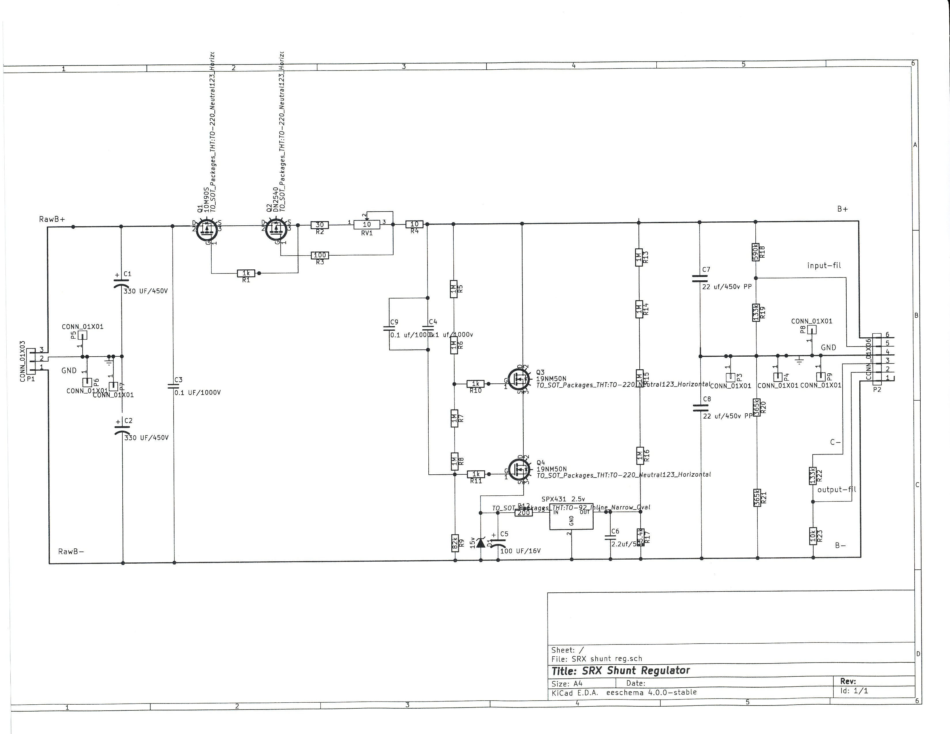
So it looks like Dr. Gilmore has posted the shunt reg PS board on his web site. As I said it looks correct to me but someone else less involved should probably check it out to make sure.
-
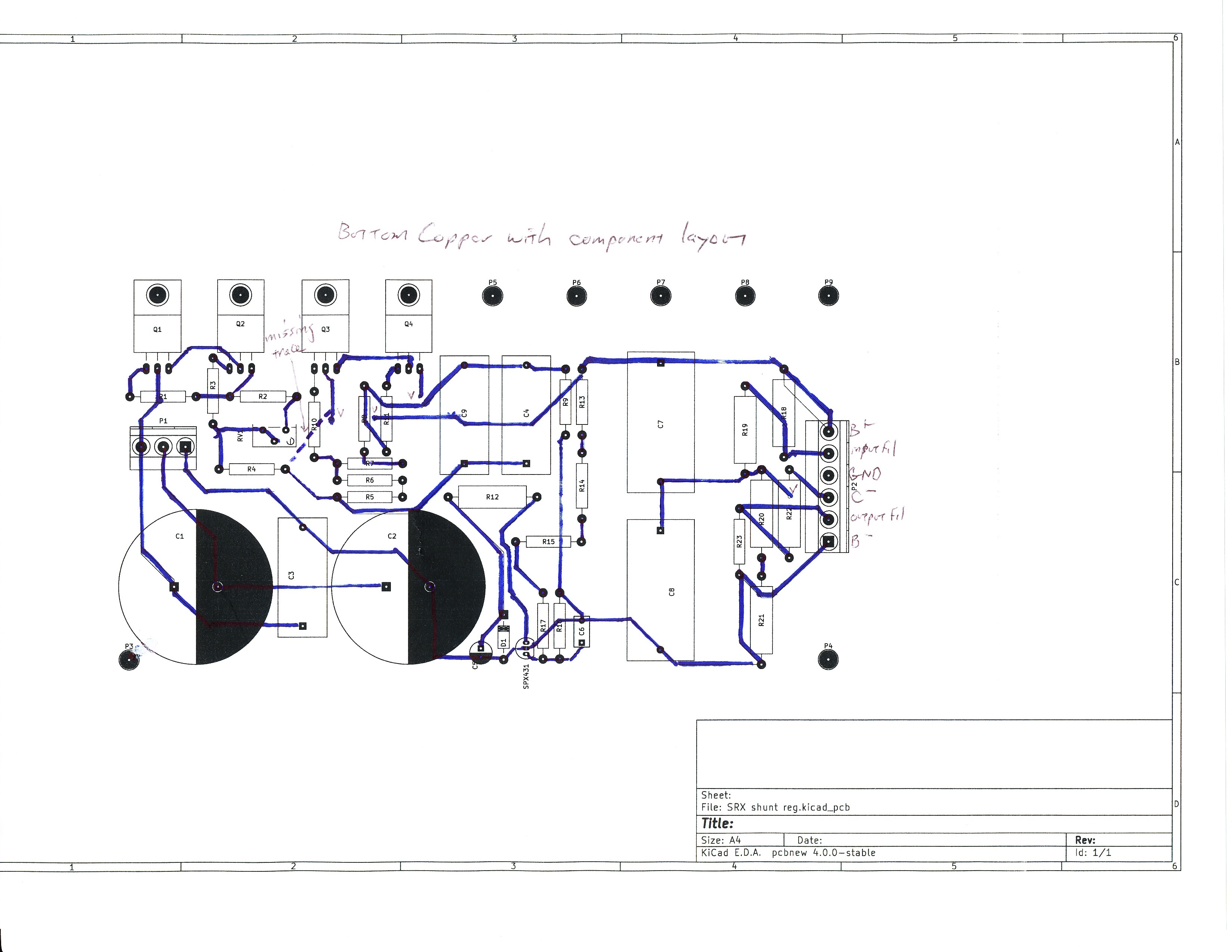
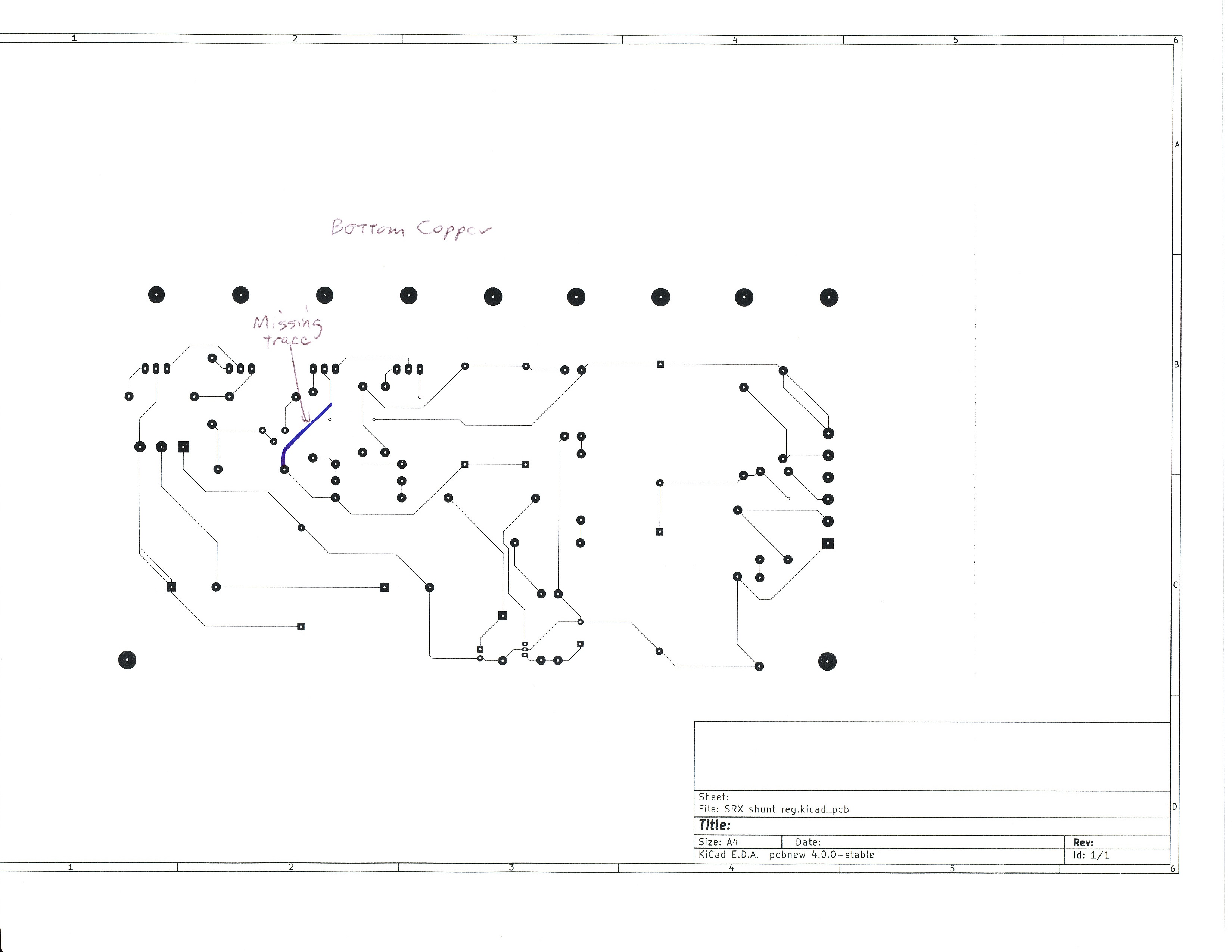
Yes, bypass caps should be put as close to the amp power entry as possible, but the main reason I put the caps on the output is based on a comment by John Broskie, "My experience with shunt regulators has been that without some capacitance on the output, expect some oscillation." Also, to go back to my previous comment about the SPX431 layout, I realized after some more thought that there was another missing connection between the output of Q4 and R12, which KG noticed and I didn't.
-
I used Audiocap Theta polyprop caps for my build because they are relatively affordable and relatively small, but any polyprop is fine, e.g. Mundorf, etc. Polystyrene should be OK also but be careful with them because they can melt if directly touchéd by a soldering iron.
-
Ah ha! The C- supply is just a dropping resistor. I don't think it needs anything else since it goes to the input tail current source which should isolate it from noise and hum. Guess that board is too big for two mono supplies. My original board without the input rectifier and bias supply was about 6.6x 3.6 IIRC, but I cut it pretty close. As long as we're at it, do you want to have provision for normal bias headphones as well? BTW, I like your layout of the SPX431 much better than mine, cleaner pathway. Told you I was new at this. Also, if anyone wants to use a off board rectifier and choke input they can just jumper two of the input rectifiers and leave the other two unpopulated.
-
Yes, the board layout doesn't show it because KiCAD doesn't have a footprint that large. But that's the specs of the TDK D-Link on the Mouser website. As Donald Trump would say, they're UUGE! On my point to point build I used Solen polypro caps which measure 2.3" long by 1.5" diameter, and they're UUGER!. That's the reason I left space on the board layout instead of bringing the surrounding resistors close to the cap footprint. I see you added the bias board. BTW, it occurred to me that with an amp using outboard heatsinks, you could use this as a mono PS, one for each channel, and between the amp and the PS the current draw should be absolutely stable, although it's pretty close in any case. Also, the reason I didn't include the rectifiers on the board was in case someone wanted to use a choke input, in which case the rectifiers would have to come before the choke, so the transformer, rectifiers and chokes would be wired point to point and the raw B+/B- and transformer CT to ground would then go to the board. Um, don't see the SPX431, protective zener and caps that are supposed to control the voltage. Also the output block should be 6 pins rather than 7.
-
Oops, one boo-boo. The labels on the board for R16 and R17 should be exchanged, R16 should be to the left of R17..
-
I'm in for 2 amp board and 2 PSU plus two bias boards
-
As I explained in the amp circuit analysis, the input cascode stage has a pretty high output impedance, close to the value of the plate resistors, which is 300 kilohms (original) or 250 kilohms (SRX Plus). In fact the resistance of the plate resistors is as high or higher than many single device current sources - for example, a single 10M90S has an impedance around 150-200 kilohms. In combination with the input Miller capacitance of the output stage, this leads to a open loop rolloff frequency of about 11-12 kHz. You need the feedback to flatten the closed loop frequency response, which rolls off above 45-50 kHz due to the open loop gain equalling the closed loop gain at that frequency. Substituting a cascode current source which has a much higher output impedance, will actually lower the open loop rolloff frequency further, which is the last thing you want, because that will cause the closed loop response to roll off earlier.
-
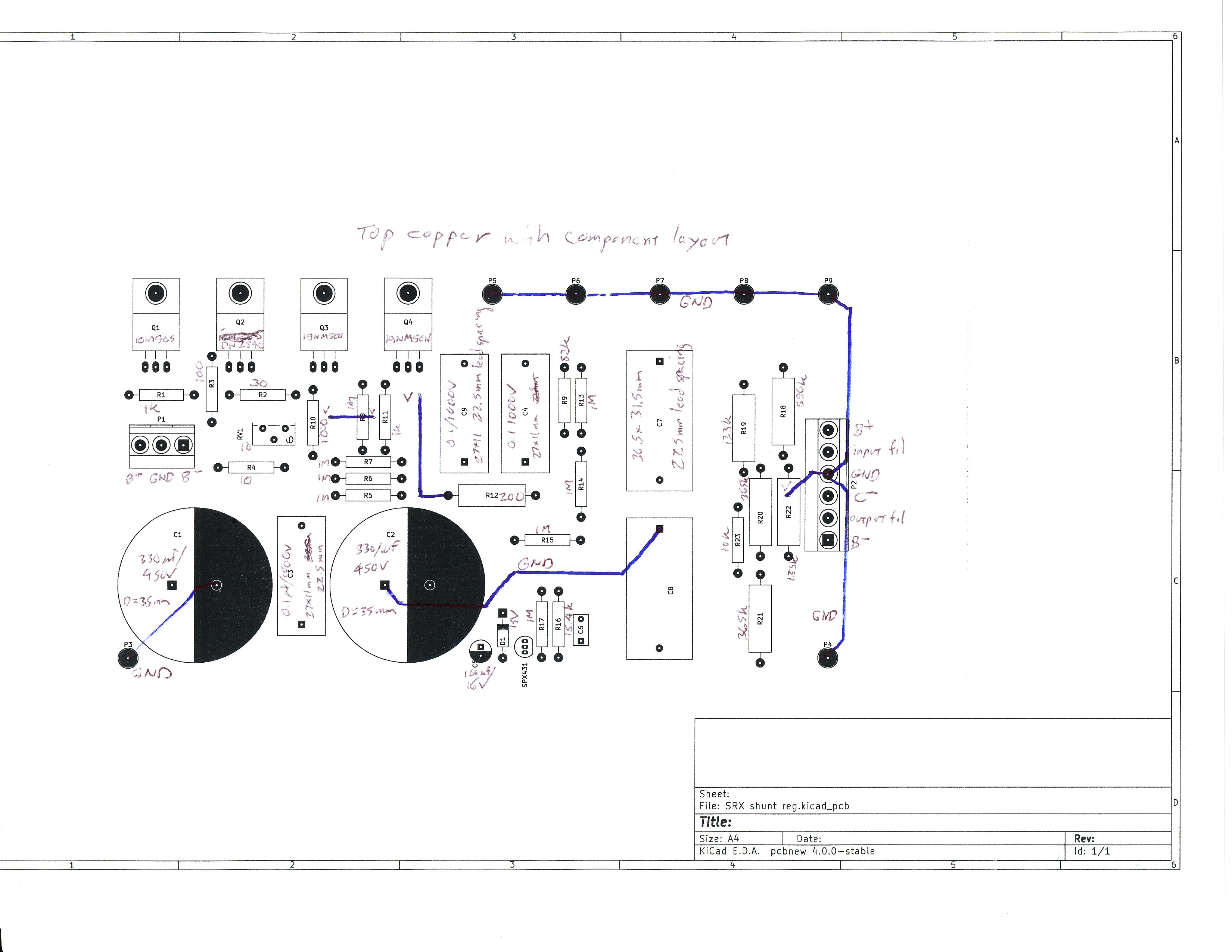
Pars, thanks for the offer, but if you haven't used KiCAD you're probably going to have at least as much trouble as I had. Dr. Gilmore, Thanks you for the very generous offer. Here are jpgs of the schematic, bottom copper with and without the component layout, and top copper. I believe there is only one missing connection. My layout uses an aluminum bracket because the MOSFETs should be able to withstand 35 watts or so if the amp boards go south and the entire current has to run through the shunt. Most of the connections are on the bottom copper, with two vias to the top copper, and a couple ground connections on the top copper which could be replaced with a ground plane on top. This is my first attempt at laying out a PCB so if you find a better arrangement feel free to change it. The 10M90S and DN2540 are available on Mouser, and I just checked that the 19NM50N MOSFETs are also available at Mouser, as is the SPX431. I chose those MOSFETs for their low on resistance, which is better than most, but other 500 volt rated MOSFETs can be used. So the input electrolytic caps are 35 mm diameter. The 0.1 uf/1000v caps (C3, C4 C9) are 27x11mm rectangular, 22.5 lead spacing The 22 uf/450v caps (C7,C8) are D-Link 36.5x31.5 rectangular, 27.5mm lead spacing C6 is 2.2 uf 50v R12 and R18-22 are at least 1 watt, 500 volt, other resistors are 1/2 watt.

-
So just a quick update. I am currently stuck in trying to design a PCB for the PSU. I've got it mostly done but there is one connection that I haven't been able to make - I mean literally KiCAD won't let me connect two parts. I've tried deleting the connection in the schematic and reconnecting it, and reloading it in the PCB design module, I've tried manually drawing it in the PCB design module - it just won't let me do it. I'm going to try starting from scratch again this weekend.