JimL
-
Posts
641 -
Joined
-
Last visited
Content Type
Profiles
Forums
Events
Everything posted by JimL
-
I think you make some cogent arguments, and you are correct about the Lundahl choke - but it also costs over $90. Electrostatic headphones are an extreme example of high impedance which requires the highest available impedance anode chokes for outputs. These are more difficult to design and more expensive. And the fact is that with music signal, which is power weighted toward bass and low mid-range frequencies, there is going to be significantly more current draw to drive the chokes than a constant current source, likely by 2-3 fold. While choke distortion may be limited to the bass frequencies, one could argue whether the large voltage swings will increase choke distortion as a whole, and the extra current draw increases tube distortion as a whole. It is true that current sources are wasteful from a static point of view (although no more so than a resistor) compared to a choke, but they are more efficient from the point of view of providing power to the transducer because very little signal power is wasted in the current source, compared to what is wasted in a choke or power resistor. And while choke outputs can use a lower voltage supply, most stat amps and power supplies are bipolar - constructing two 400 volt power supplies is no harder than constructing one, While choke outputs are not necessarily a bad idea, I think that current source outputs are a better idea for stat phones. Perhaps the trade-offs of choke outputs may make more sense for dynamic drivers which have a much lower impedance, but that's a wild-ass guess as I haven't really done any analysis.
-
I AM using that topology for my SRX Plus. But it is rather bulky and heavy. I used surplus transformer and chokes so those tend to be bigger than absolutely needed.
-
As an example of the difference in sound between a resistor load and a constant current load here is a post by Congo5 on the Output Stage Current Requirements thread from April 24, 2015: After building the SRX Plus I decided to try the CCS on an Egmont. Copying Kevin's layout I drew up this: Having two Egmont's I can A/B them to compare. It is a huge improvement, more volume and much less distortion. Much more of a usable amp now. Noticeably cleaner bass. like Night and Day.
-
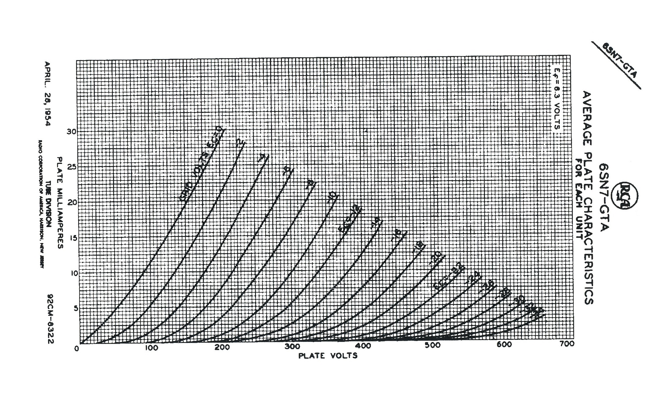
Nope. The active device, we'll use tube for simplicity, should be relatively low output, but because the headphones are so high in impedance, even an output of 5-10k is adequate - in fact the Stax headphones all have a 5.1k resistor in line between the output device and the headphone to protect the latter. Being high in impedance, the headphone needs large voltages but relatively low currents. Hence, a 6SN7GTA with its DC voltage limit of 450volt and running 7-8 mA makes a good output device - IF all its output current goes to driving the headphones. But, if you waste a good proportion of that current in the amp load, it isn't nearly as good. Remember that the output tube drives the headphone in parallel with its load, whether that be a resistor, a choke, or a constant current load. This means that the music signal current is distributed between the headphone and the load depending on their relative impedances. On the other hand, the output impedance is the impedance of the tube and the load in parallel. With a tube plate resistance of, say, 8k, even a perfect constant current load with an infinite impedance results in a combined output impedance of 8k. With a resistor load of, say 50k, the output impedance is about 6.9k, a negligible difference. With a choke load, the output impedance varies with frequency, being higher as the frequency rises, but mostly dominated by the plate resistance. So the output impedance is pretty similar regardless. In order for the tube to have a reasonable standing current, the resistor has to be around 50 kilohms unless you have a very high voltage power supply. Since the impedance of the headphone is much higher than 50 kilohms, this means that most of the music signal current is wasted in the resistor. With a choke of 100H, the impedance is only 12.5 kilohms at 20 Hz, and only gets to 50k and above at 80 Hz and above, and doesn't exceed the impedance of the headphones until you get above 1 kHz. With music signals, about 1/2 the power is in the range below 300-400 Hz. Again, this means that the majority of the music signal current is used to drive the choke, and the leftovers go to the headphone. This is not only inefficient, it causes more distortion because the tube has to supply much more current. With a really good current load of very high impedance, there is practically NO current going to drive the current source, so nearly all the current goes to drive the headphones. Do a search for the thread "Output Stage Current Requirements for Electrostatic Headphone Amps" for my full technical discussion. The bottom line is, the output load is the plate resistor/choke/constant current load in parallel with the headphone. A perfect constant current source needs no current drive so it is invisible to the output tube, which sees only the headphone load. This is the best possible situation for the output tube. On the other hand, the output impedance is the impedance of the plate resistor/choke/constant current load in parallel with the plate resistance of the tube. Since the tube plate resistance is much lower than that of the plate resistor, etc., the output resistance is primarily the plate resistance. So a constant current load has no significant disadvantage in terms of output impedance compared to the other two options. Finally, a constant current load does require a heat sink, so it is more expensive than a resistor, but still significantly less expensive than a good plate choke. So, the constant current load is by far the most efficient in directing the signal current to the headphone, resulting in the least distortion and most output, has no significant disadvantages, and reasonable expense.
-
The heart of the matter is this, it's not about what sounds "good" or "OK". It's about how to get the best sound. An electrostatic headphone is inherently a high impedance device. The best resistor or choke is always going to limit how good the sound can be, because it is always going to suck the majority of current from the output device to itself, diverting it from the headphone, because it is lower impedance than the headphone. That is simple Ohm's law. That means the output device is always going to more distorted than necessary. A really good current source is MUCH higher impedance than a electrostatic headphone. That means most of the current from the output device actually goes to drive the headphone rather than being wasted generating heat in the resistor or choke load. Better efficiency, lower distortion, better sound. Simple. So, Pirx, build an amp with choke output and the same amp with a good MOSFET cascode constant current source, listen to both and then get back to us.
-
Also, the KGST is similar to an SR007T but with a much better output tube (6S4A vs two halves of 6CG7) and CCS load, plus a regulated power supply for that last extra bit of sophistication and oomph.
-
"Go do something you hate. Being miserable builds character!" - Calvin and Hobbes
-
A couple things. Put simply, a choke is an inductor and an electrostatic headphone looks kind of like a capacitor. Look in any electronics textbook and you will see that when you connect an inductor with a capacitor you get a resonant circuit, which means you can have a peak in the frequency response at the resonance frequency. I said the headphone looks “kind of” like a capacitor. It doesn’t exactly resemble a capacitor because it makes sound, which means it uses power. The power spectrum of music is highest in the mid-bass to lower mid-range areas (approximately 50-300 Hz). The impedance of a choke rises with frequency, which means that it requires more current to drive it at low frequencies, exactly where the headphone is requiring the most current and voltage to make music. This increases the distortion of the output device. The largest commercial plate choke I have found runs around 200H. This has an impedance around 25 kilohms at 20 Hz, rising linearly with frequency from there so at 40 Hz its impedance is 50 kHz, which is a typical resistance for a stat amp plate resistor. So at the lowest bass frequencies it requires/diverts more current from the headphone than a typical plate resistor. This is all based on an ideal choke, ignoring the possible resonances and other imperfections of a real world device. With a resistor load, you don't have the possibility of a peak in the frequency response but the resistor requires curent to drive it through the whole frequency spectrum. In fact, with a resistor load, the amplifier actually wastes more current (and power) driving the resistor than driving the headphone. By comparison a really good current source load demands a negligible amount of current, which means all the standing current of the output device is available to drive the headphones, which is what you want. As I said elsewhere, it converts an amp for driving output resistors to an amp for driving headphones. It is simply a better technology. This is why Stax has used current source loads in its solid state amps in place of resistor loads since the 1970s.
-
So it sounds like you came up with the circuit independently. Not the first time that has happened, nor will it be the last. In case you are not aware of it, Kevin Gilmore is, IMHO, the best headphone amp designer around. He designed the Blue Hawaii, KGSS, KGSSHV, KGSS Carbon and Megatron electrostatic headphone amps, along with an excellent series of dynamic headphone amps. If you are interested in building a more powerful tube stat headphone amp, I suggest you consider my own humble contribution, which is discussed in the "SRX revisited" thread elsewhere in the DIY section, and is simple enough to be built point-to-point. The few people who have built it so far seem to like it.
-
Some comments about the original post. The overall topology is similar to the back end of Kevin Gilmore's original all triode amp, with CCS substituted for plate resistors. The use of a CCS on the output stage will make it more efficient in driving the headphones compared to a plate resistor, which is beneficial. But, the output tube is not a good choice. Its max DC plate voltage is 300V, but more important, its max plate dissipation is only 2 watts which significantly limits the amount of current it can supply without burning up. Consider substituting a 6CG7/6FQ7, which appears to be pin compatible. It has a max DC plate voltage is 330V, and its max plate dissipation per plate is 4 watts (total plate dissipation is 5.7 watts). Then you can increase the output CCS current to set the output plate voltage 1/2 way between ground and B+. The downside of this substitution is that this tube has a mu of 20 vs 27 for the E80CC, which is about 2.6 dB less gain, You may need to decrease the feedback resistor R5 to maintain some overall feedback to stabilize the gain, but the increased current drive is useful, as devices seldom sound their best when driven close to their limits.
-
Yes, I left mine on overnight also, when I was testing my build, except that I did it on purpose. The current and voltage parameters were chosen so that it should need no more care than a typical TV. You fall asleep in front of the TV and wake up in the morning - no big deal. Incidentally, here are the plate curves for a 6SN7GTA from the RCA specifications: Notice that the plate voltages run up to over 650 volts, which is higher than the maximum voltage that these tubes will see in the SRX Plus design (assuming +/-325 volt supplies). And incidentally, the largest consumer use for these tubes was in black and white TV sets. If they hadn't been reliable the screams from consumers would have been epic.

-
Each of the output current source heatsinks has to handle less than 2.5 watts apiece, or roughly 10 watts for the amp board, so it's not as if there is a huge amount of wattage trapped inside the box.
-
Glad you like the sound.
-
Re: buzz. Obvious things to do are 1) make sure the filament (heater) wiring is twisted tightly, and 2) keep the filament wiring away from the inputs and run them so they are perpendicular to any signal traces if possible.
-
Correct. Upper and lower refer to the schematic where the lower tube accepts the input and the upper tube drives the plate resistors and output stage.
-
Steps 1-3 and step 5 are correct. Note that my design uses 250k plate resistors for the input stage cascode whereas KG'b board lists 300k resistors. If you use 300k the input stage current should be 1.1 mA, if you use 250k resistors it should be 1.3 mA. Step 4 should be: set the INPUT balance to 0 VDC by adjusting the 5k pot. You are trying to get the upper 12AT7 plate voltages to be the same. An easy way to do this is to connect your meter leads between the "bottom" of the two 12AT7 plate resistors and adjust the 5k pot to zero volts. As for the post from 5/06/15, this is to balance the output voltages to close to zero. Basically you do the step 5 adjustment which should get the outputs within 10 volts of zero if the 6SN7GTA is reasonably well balanced. What this means is that one output may be +7 volts while the other is -5 volts, for example. Honestly, this is close enough. However, for those compulsive obsessives, if you want to get even closer you can adjust one or the other of the plate loads so the output voltage is the same for the plus and minus outputs, then re-adjust the current sink to zero everything. Now, because you are dealing with tubes, the plate voltages are likely to drift by several volts over time even if you can get it zeroed- unlike solid state, it's not going to stay stable, but 10 volts or so is not going to make any difference whatsoever. Furthermore, every time you turn it on the final voltage will be somewhat different, but usually only by a few volts. So one time it may be +5 and -3, another time it may be -2 and -10, another time +4 and -4, and also over time during one turn-on cycle you may see all of those values during a couple hour period. Usually the off set between plus and minus outputs is pretty constant but the actual value (with respect to ground) may vary.
-
The input tube cathodes are sitting at around 0 and +80 volts give or take so I set the input filament tap at around +60. The output filaments are sitting at around -310 volts (for a -325 volt PS) so I set the output filaments around that voltage. These filament "bias" voltages are incorporated into the shunt regulator supply. However, as mentioned, floating the filaments is perfectly OK so this is not really necessary - it's just feeding my OCD . If you float the filament windings they should automatically adjust to a safe limit. Otherwise, if you want to bias the filaments, you can use the 590k and 133k resistor string from my shunt reg supply across the B+ to set the input filament voltage, and the 10k and 100k resistor string for C- to set the output filament voltage. "
-
BTW, let me emphasize that it is absolutely ESSENTIAL that the heatsinks for the PS board are attached to the MOSFETs before it is tested, otherwise they can and probably will blow up.
-
My boards arrived, looks good!
-
BTW, MLA noted a "problem" on his original board, which is that the input stage plate resistors are specified as 300k, which is what the original SRX has. With that value, you have to set the input tail current source to about 1.1 mA to get the input stage plate voltage to 1/2 way between ground and B+. I changed the input plate resistors to 250k - for that value, the input tail current source should run about 1.3 mA. Either value is acceptable, just that you have to adjust the current source to give the proper plate voltage on the upper tubes, which is 1/2 way between ground and B+, or 160 volts if you're running a +/- 320 volt PS.
-
This is why transistors are also called 3 legged fuses
-
Looks quite a bit smaller than the original BH IIRC. A mini-BH?
-
Hey, spritzer, Is that a grounded grid board with EL34s in the back?
-
and now for something completely different part 3
JimL replied to kevin gilmore's topic in Do It Yourself
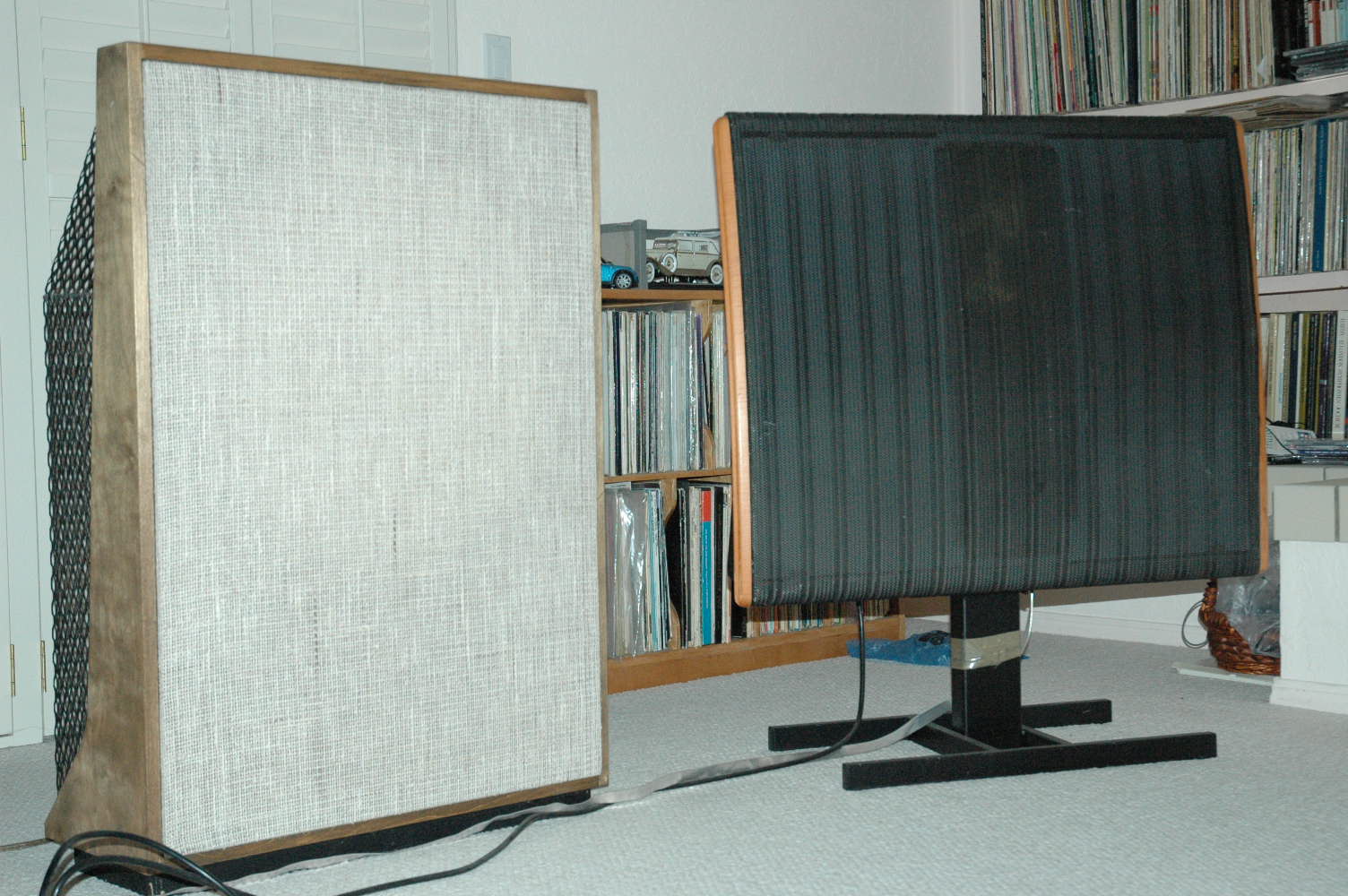
Welcome to the Quad side! I've had mine since the early 1980s.
-
Possibly to make it easy to replace tubes, or as a style choice. The tubes don't make all that much heat, unlike EL34s in the DIY T2, BHSE, Megatron, etc. In my build they were inside the case, and the KGST, which makes a comparable amount of heat, also has the tubes inside the case. In this case it's just what Dr. Gilmore decided to do. See pongo5's build in the SRX thread for an example of how to build it.