spritzer
High Rollers
-
Joined
-
Last visited
Everything posted by spritzer
-
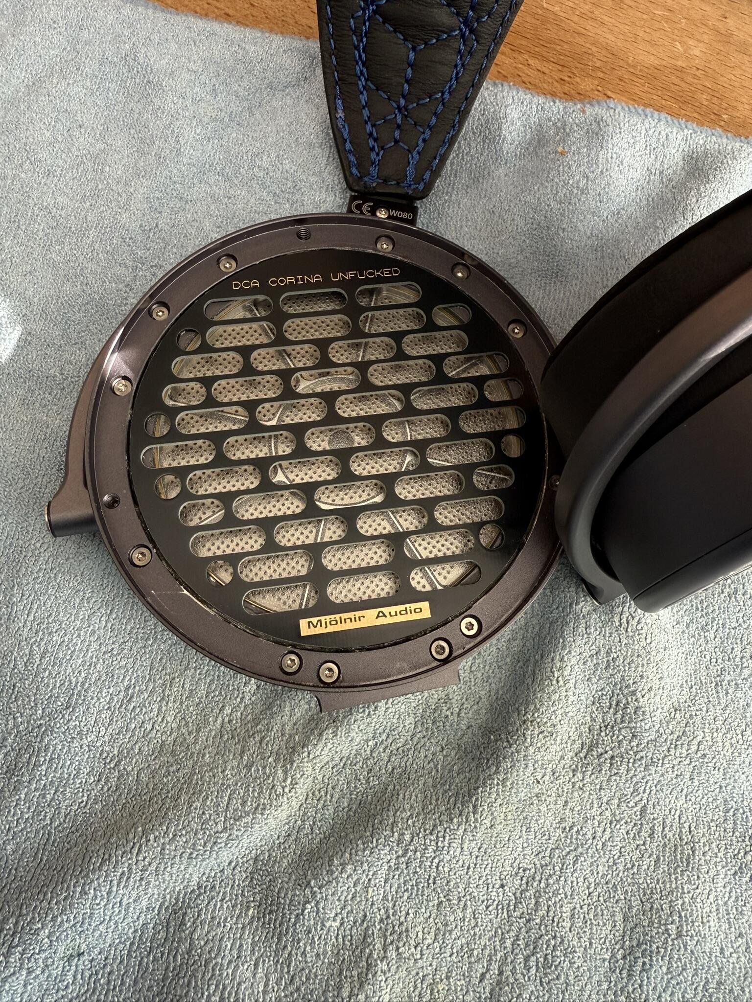
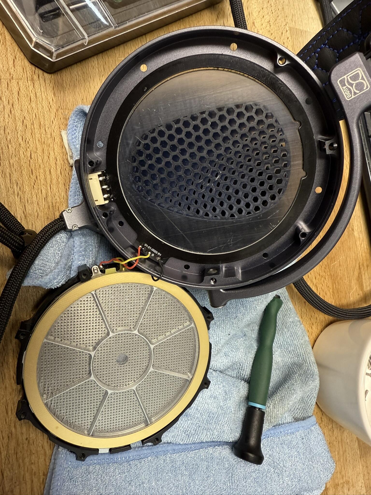
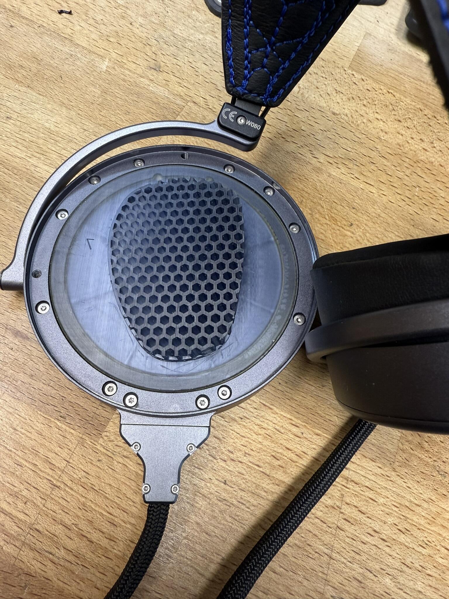
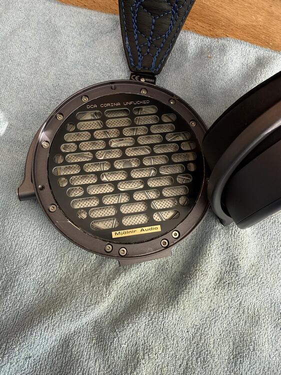
The pcb's showed up and the "unfuck" mod has been applied. The grill does help tame the top end a little bit and the end result is quite good. Still some irregularities but I'm not bothered enough to spin up a couple of new plates to try and change that. Now would I recommend this mod to anyone? Yup, the Corina sounds like shit in stock form and this totally transforms it to something not quite perfect... but far superior to stock. Now would I recommend anybody actually being crazy enough to do this... no! The plastic discs are really glued in there and getting the shards of plastic out there... well it isn't pleasant work. Some blood was spilled and injuries sustained plus some nasty chemicals used. Now I'll go back to listening to them which I'd never want to do in stock form
-
The distance from earth to AC and other components is scary small there. I'd at least put in isolation slots as the voltage can creep over the PCB.
-
Another F-tier company.
-
Yeah, never seen anybody except the hack Craig actually use that one.
-
Nothing more fun than peeking inside a "balanced" preamp to find a dual gang volume control... 🙄
-
I'll post some CRBN2 impressions soon, might even make a video about them. I've had the idea for years now to document all the weird and wonderful electrostatics in my collection and some impressions in video form.
-
I love it!!
-
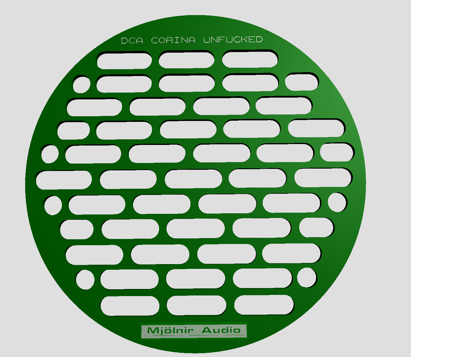
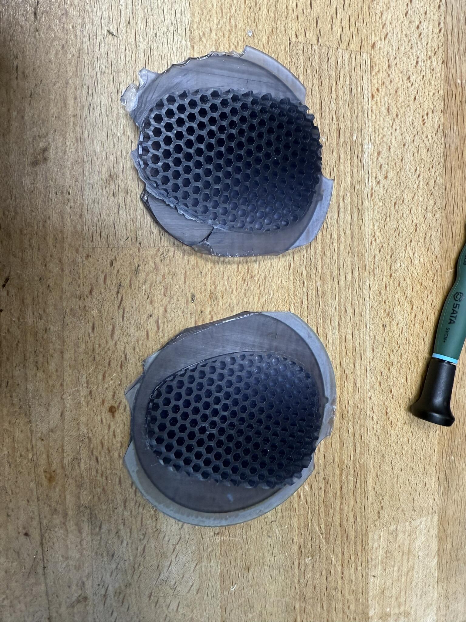
There is clearly some upper midrange/lower treble weirdness going on but to cover ca. 40% of the driver face in solid plastic and then obstruct the rest of it makes zero sense to me. I can take a bit of that odd behavior on some tracks over having headphones I just didn't want to listen to at all. Btw. driver cover whipped up in 3 minutes and already ordered. Naturally in black and gold... Not looking forward to removing the rest of the plastic crap in there though.
-
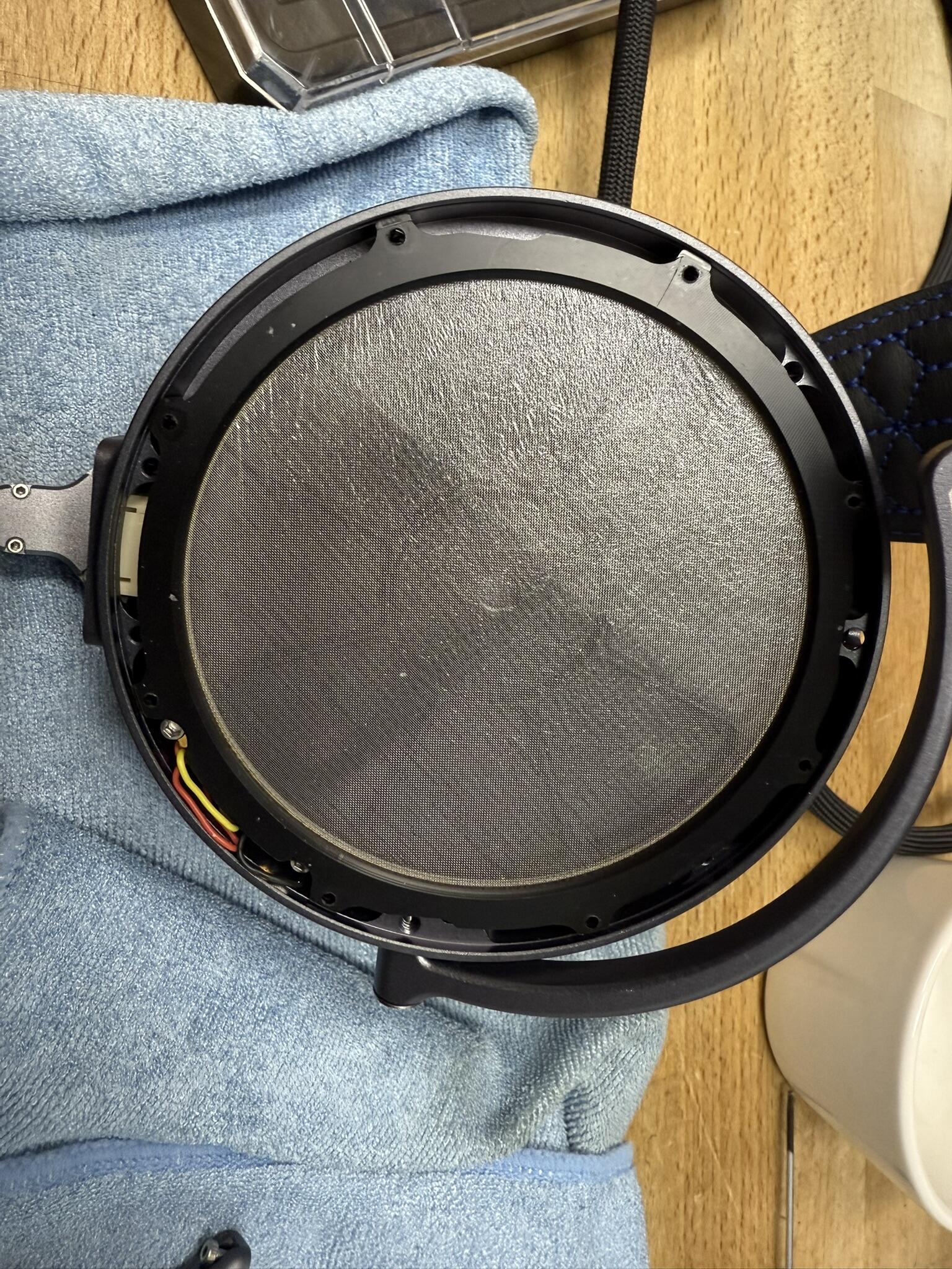
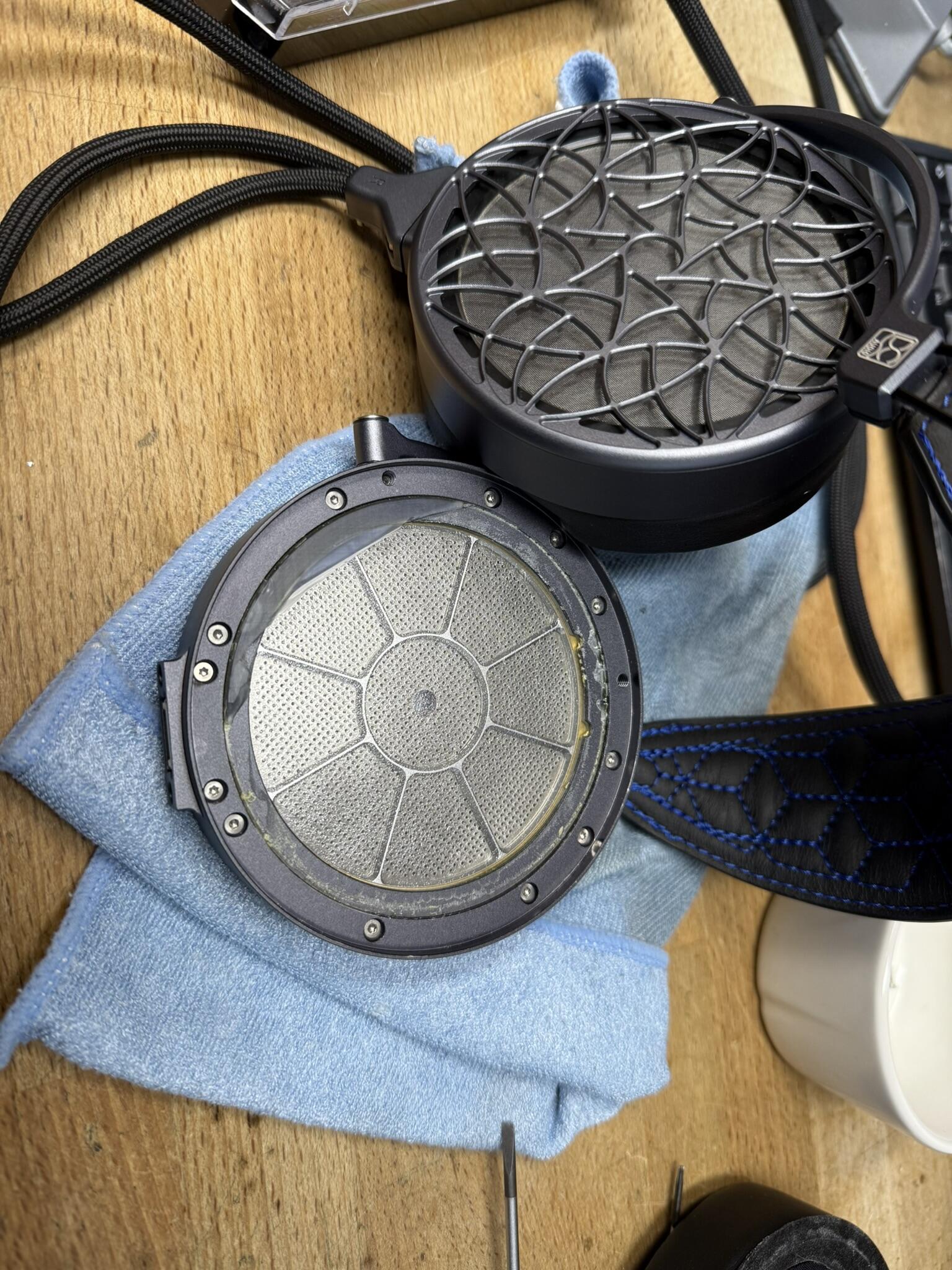
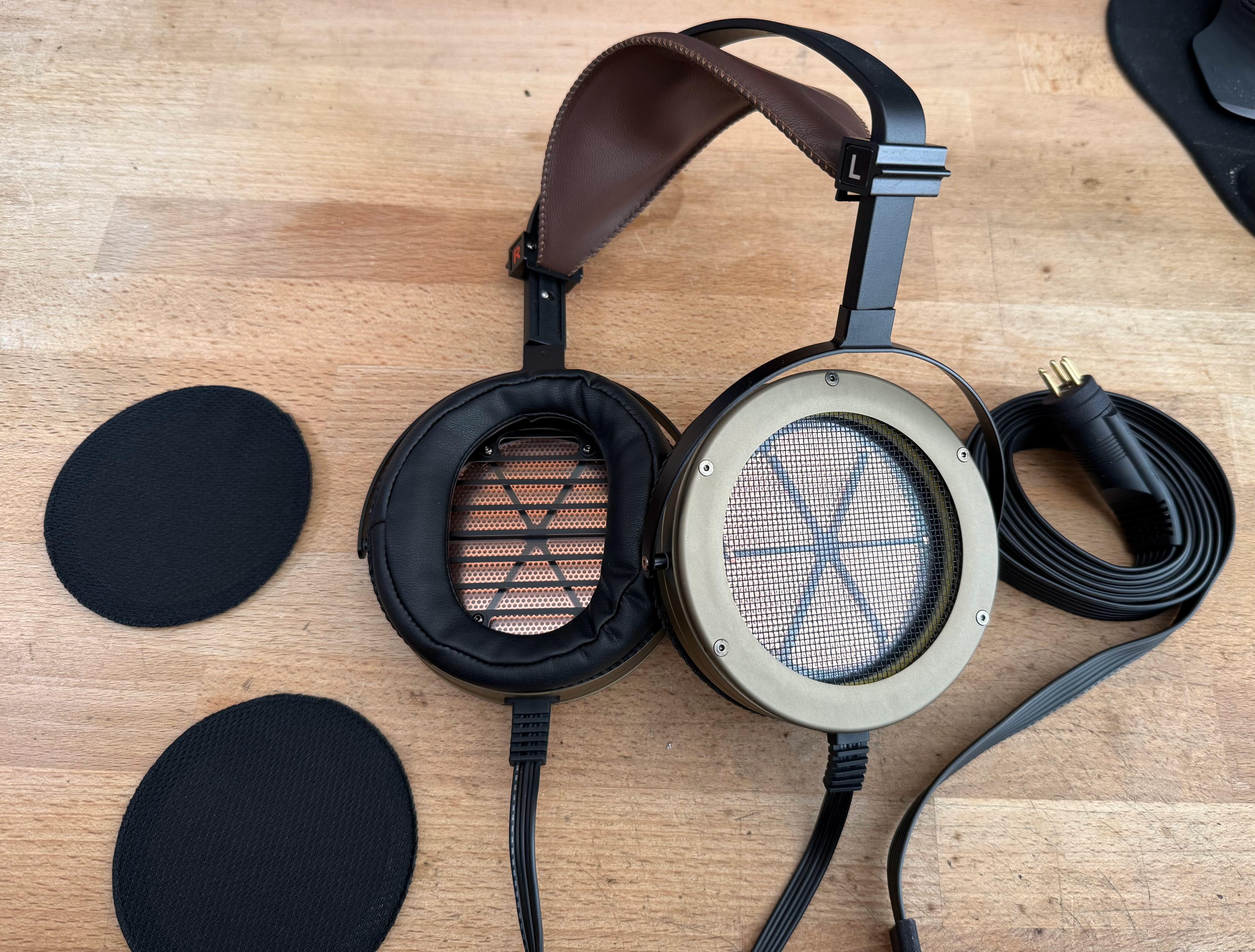
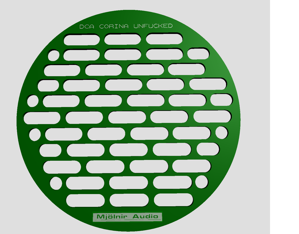
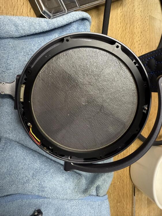
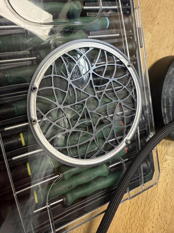
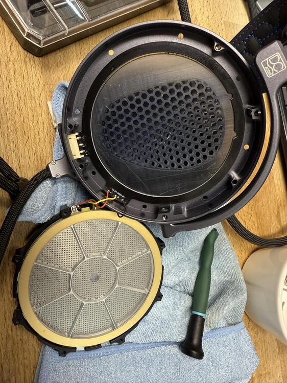
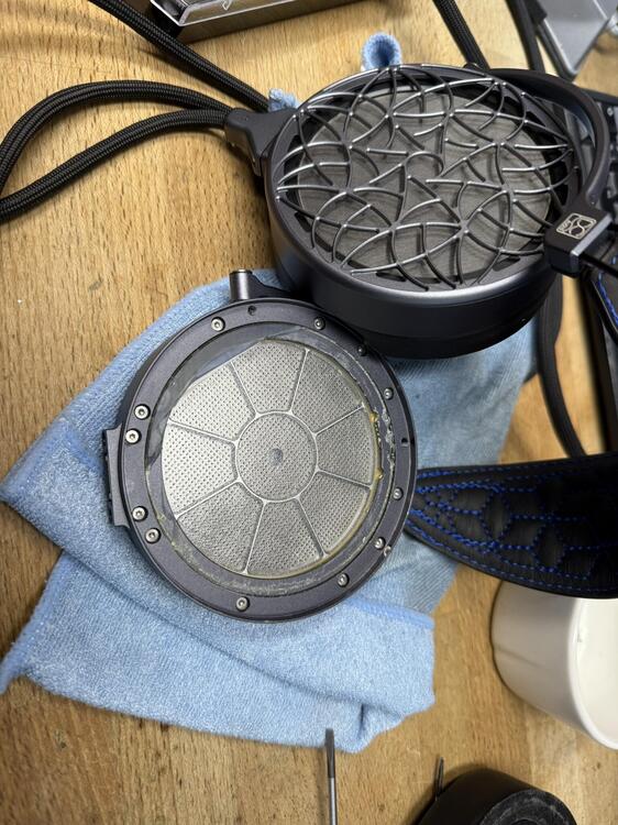
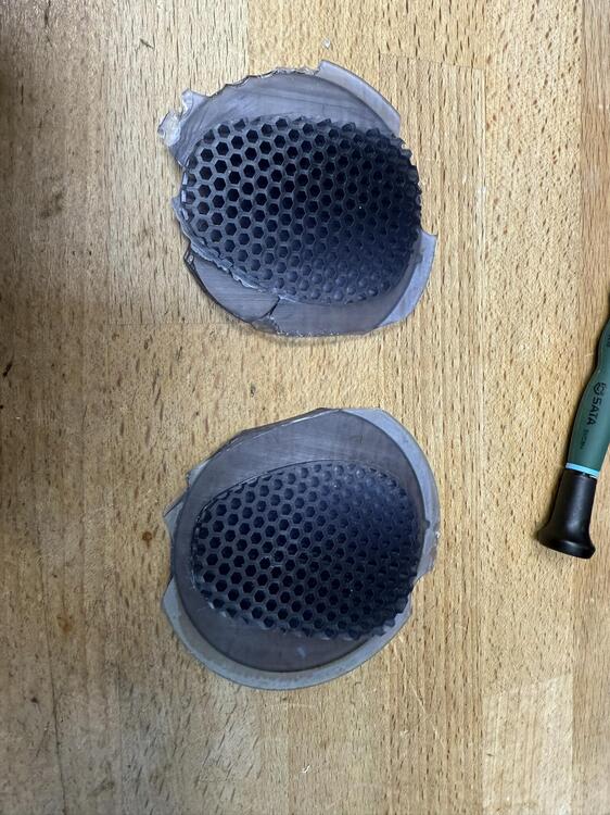
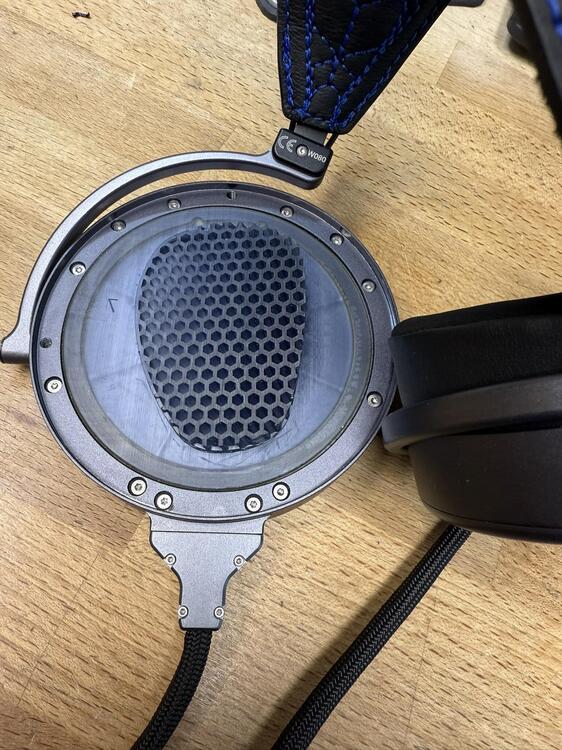
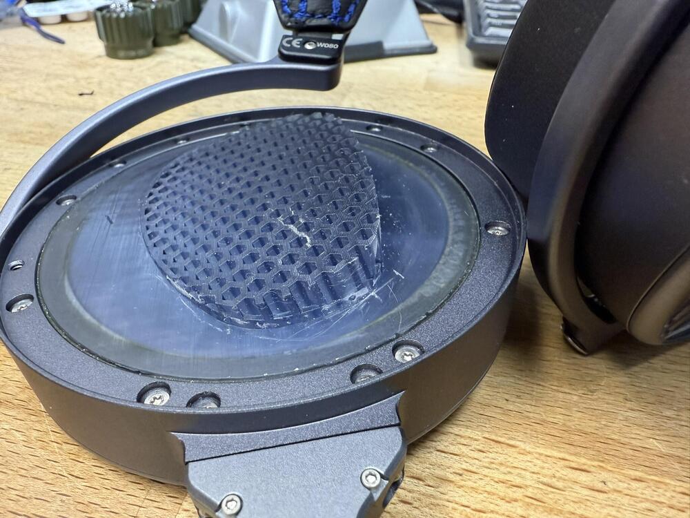
I did some further digging: Drivers are accessed from the back and this is a nice piece of aluminum. The driver is in a plastic carrier but somehow the dust cover on the front is not included and was just loose. I was told that these drivers were supposed to be easy to service in the field but that is just a flat out lie. I lifted the cradle out of the aluminum shell and the dust cover was left behind... how does that make any sense? Dust intrusion is a major issue so if somebody is going to replace a driver the first thing you do is expose it to dust. Makes zero sense to me... You knew it was coming, I went all viking on its ass... I simply used a flatblade screwdriver to vedge underneath the lip of the plastic and slowly the adhesive gave up... most of the time. The other channel was much more difficult though so this is not easy. Plus I left the driver in there so exposed face of the driver means one slip and you've done some major damage. There is still some remnants left over but I'll likely design a simple PCB that I can glue into place to protect the driver. Let's call this the un-fuck mod... Now for the sound, it is a definite improvement. Is this sound staging I hear... in an electrostatic? Perish the thought... Much better bass too and everything sounds more alive. There are some midrange issues present in drivers though, especially on voices when I push the volume up a bit (remember these are roughly 6dB down from the Stax norm) but it is still a stark improvement over the stock headphones. More listening needed and a quick PCB session...
-
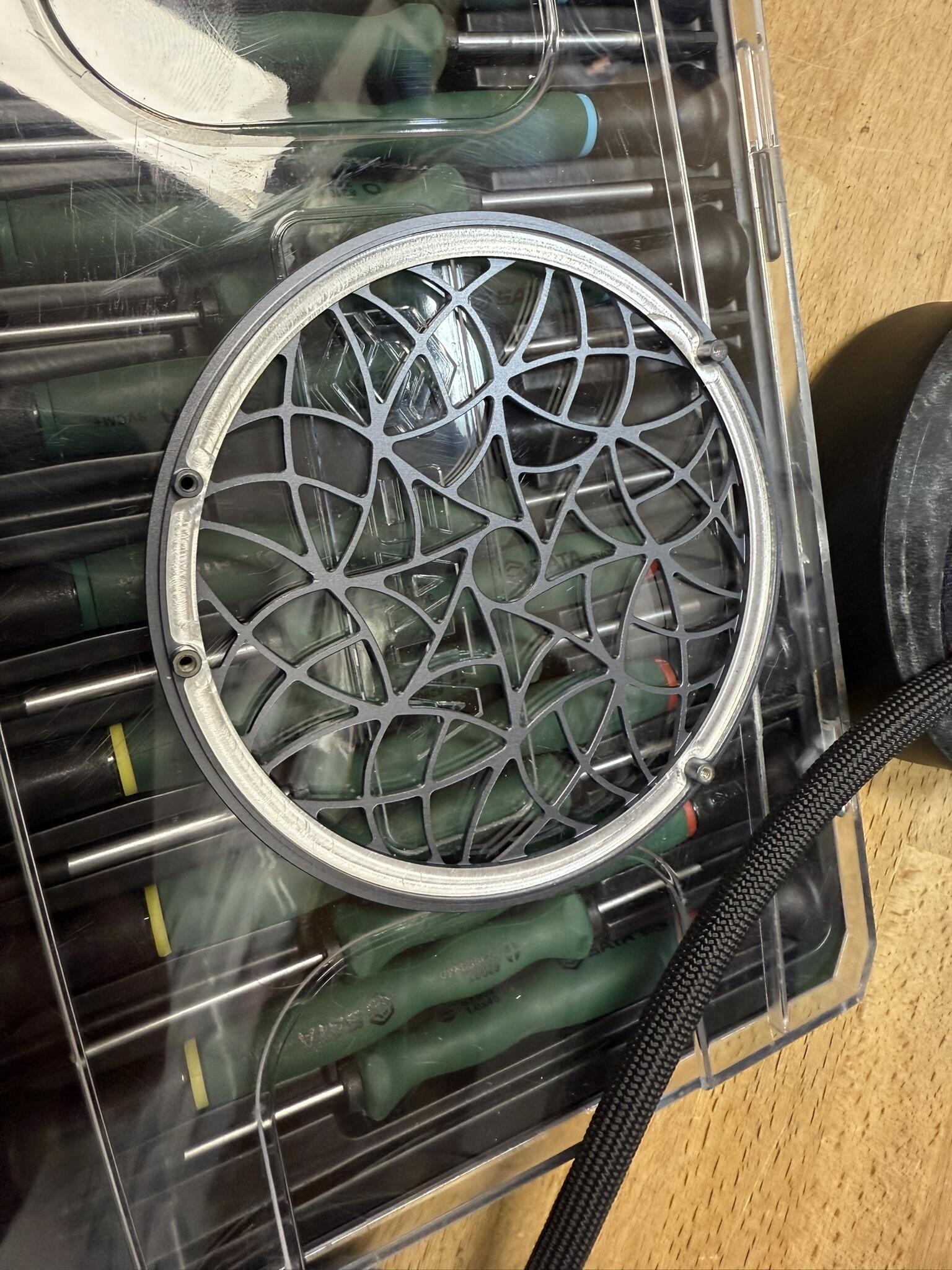
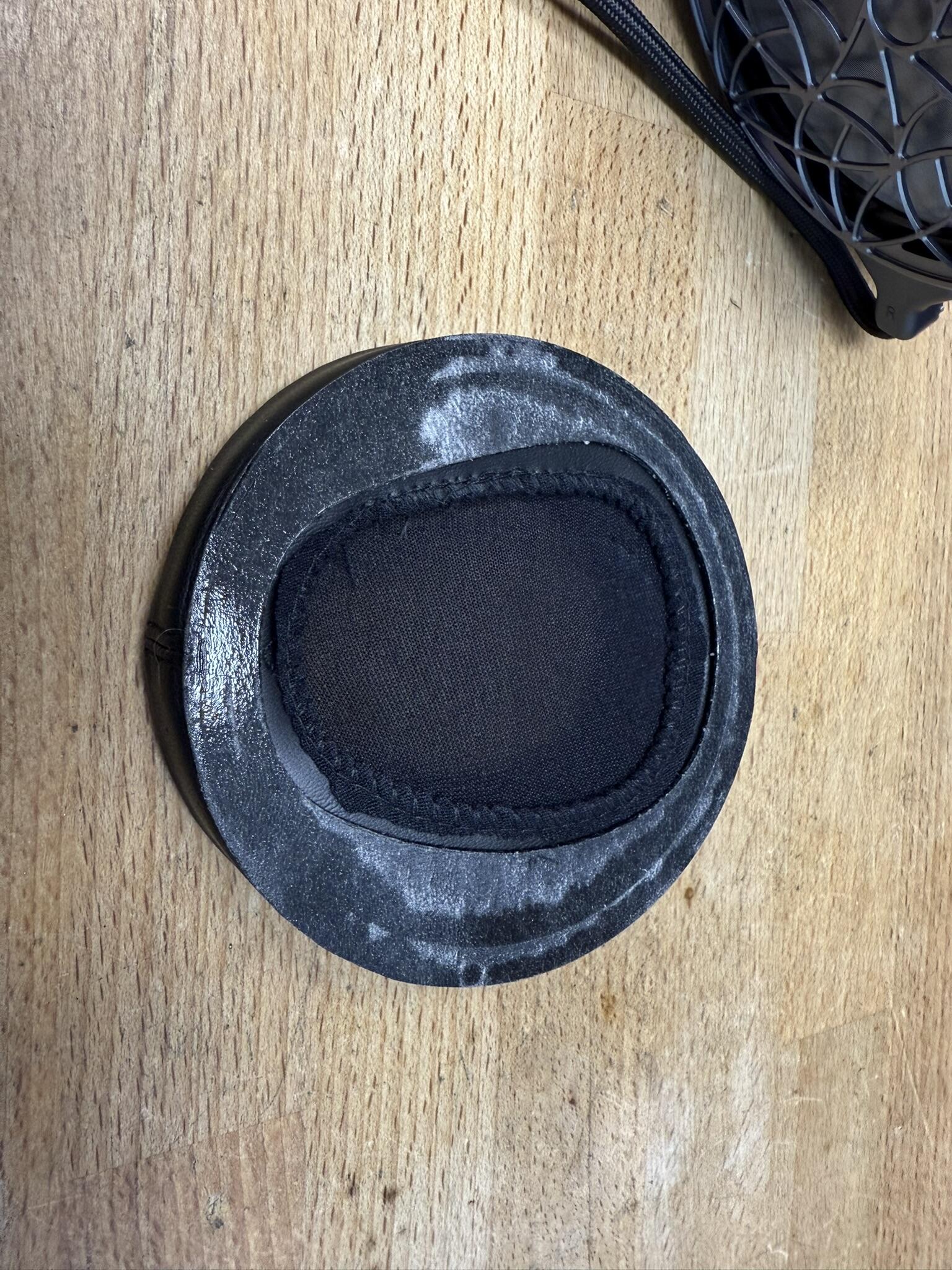
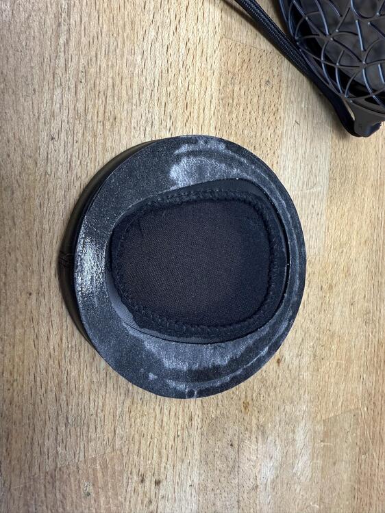
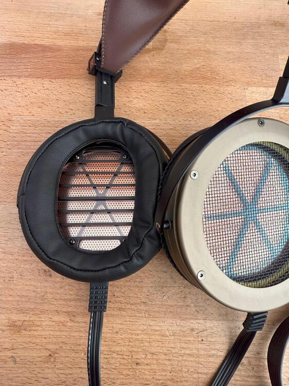
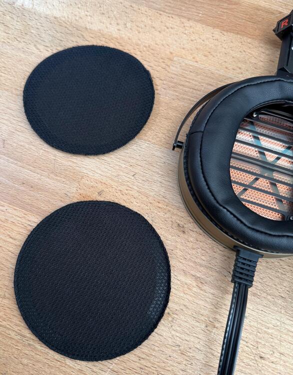
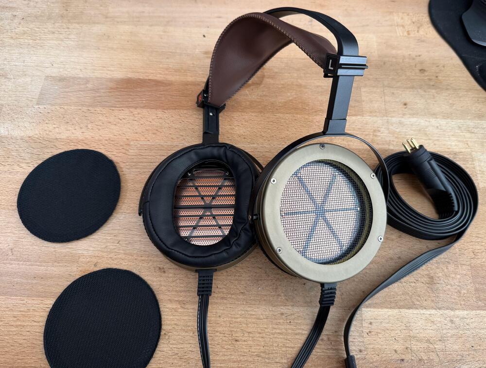
There isn't enough room inside the earpads to do any real repositioning for me , maybe 10mm back and forth max. I didn't spot any meaningful difference. The headband is just horrible, too much clamping for me and no good way of adjusting that out of fear of breaking it. It rings and it always wants to twist on me I grew to hate the Voce over time (well a couple of good listening sessions) and the earpads were huge part of that. I heard them again at Canjam with the angled ether pads and they are much better. I told the people manning the DCA booth that "wow, there were utter trash but now they are good" and they didn't like that comment all that much. If I remember correctly they replied in a fit of rage "they won awards!!!". Yeah as if anybody puts any stock in that trash. No major failure point them that I can spot, nice materials and all that Edit: Okey I got fed up and ripped off the earpads. Just look at this stupidity!!!!! The only thing that springs to mind is why on earth would anybody do this? I'm going to dig deeper and see if this trash can be removed. Btw: The earpads are simply glued in:
-
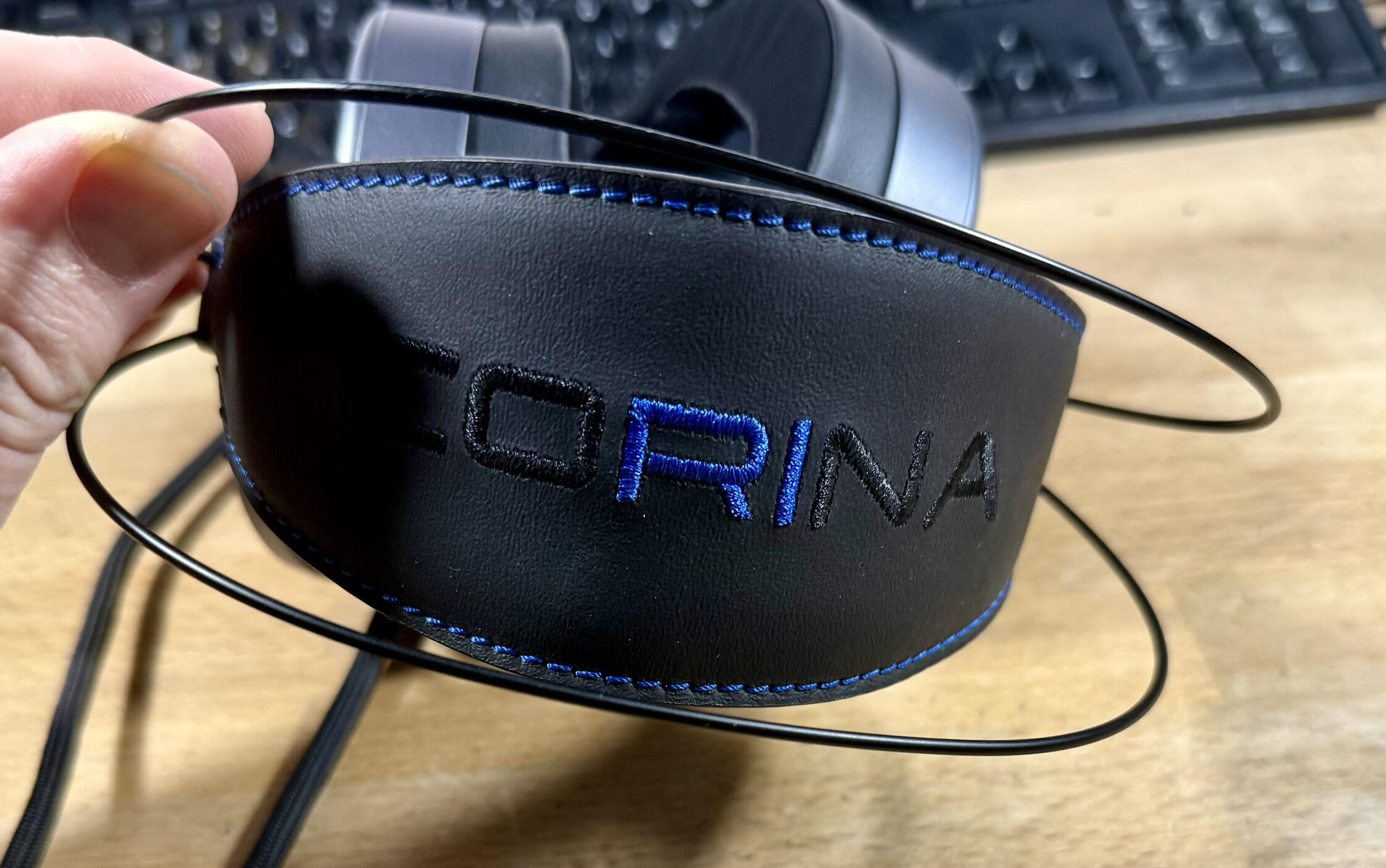
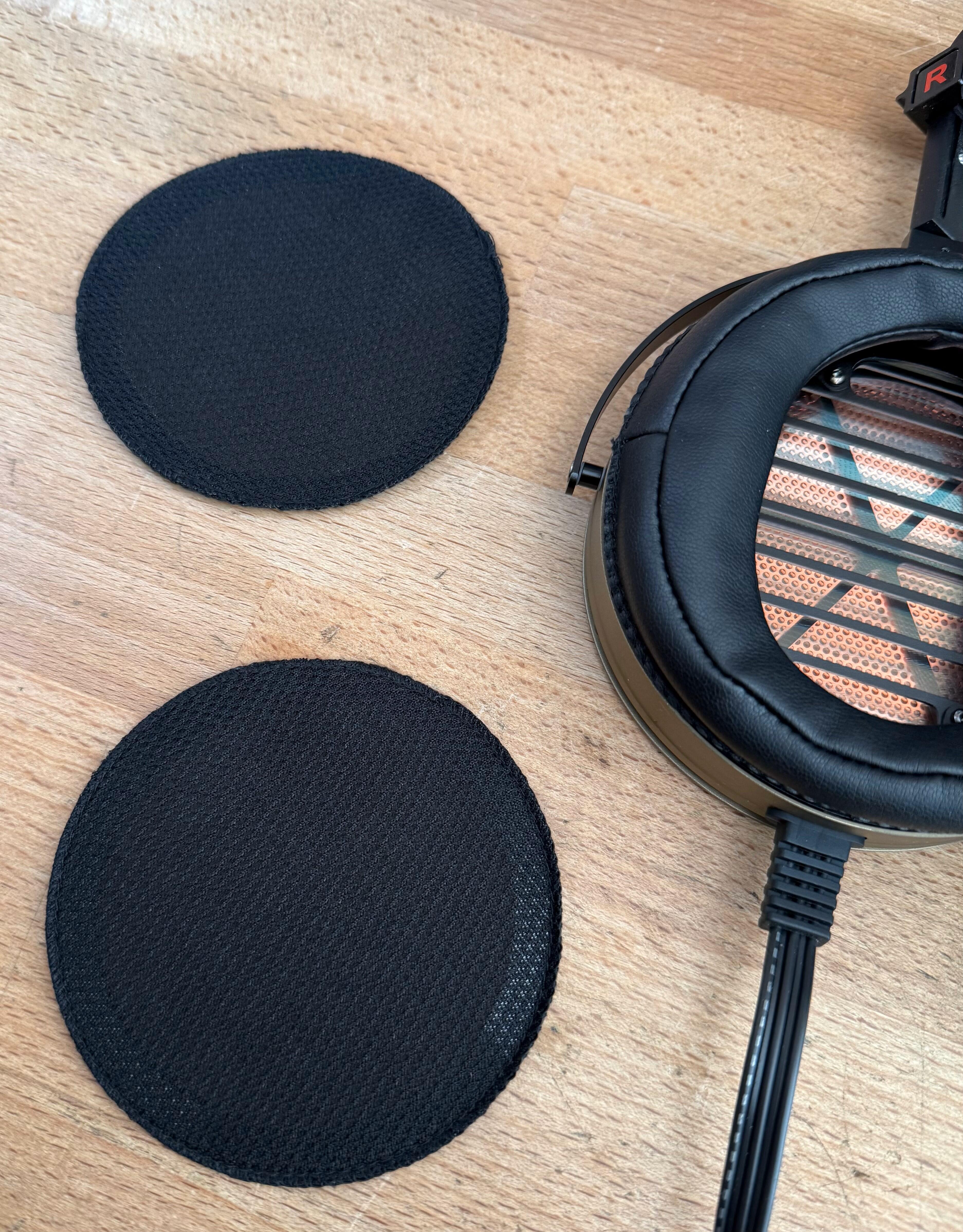
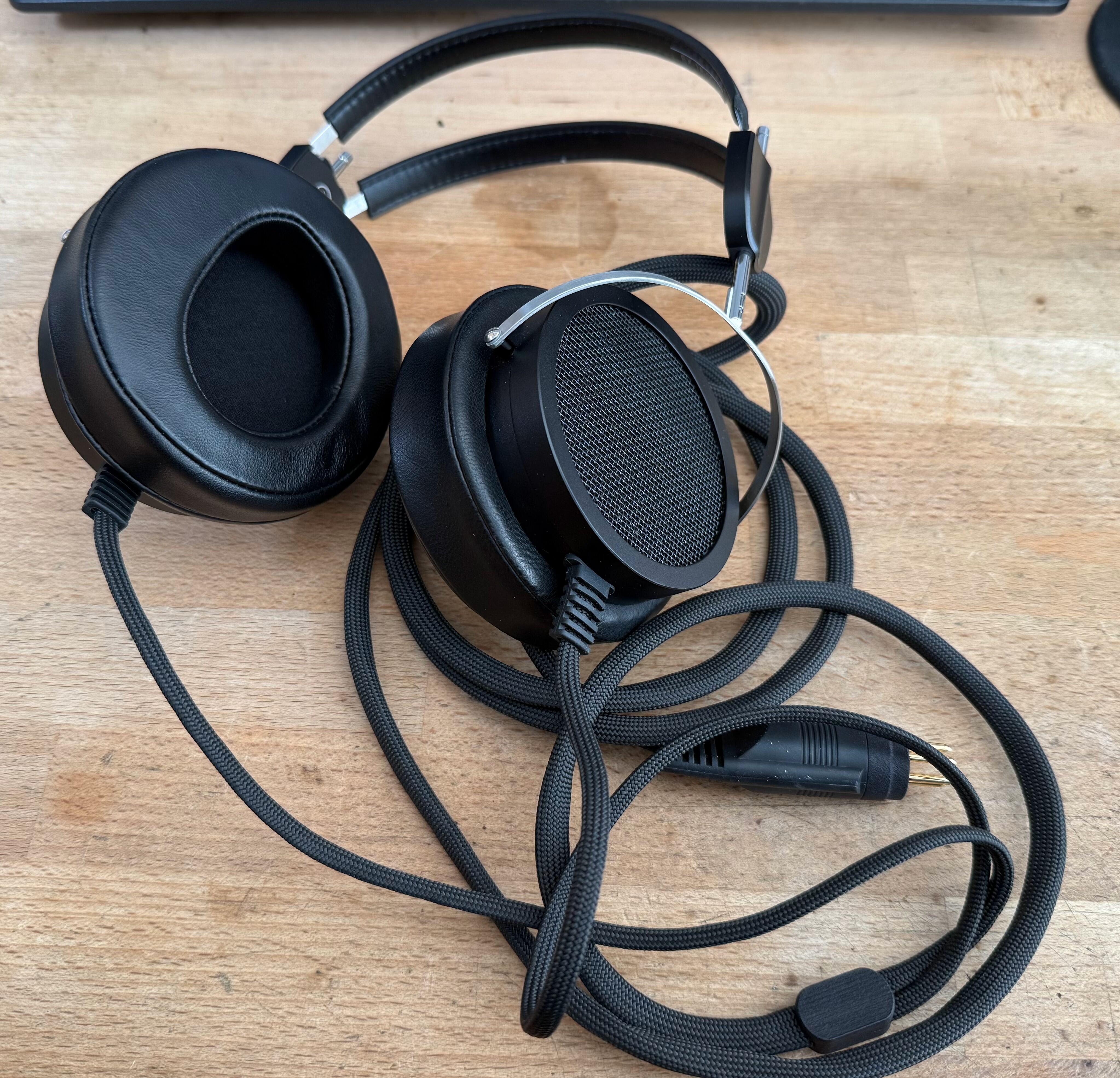
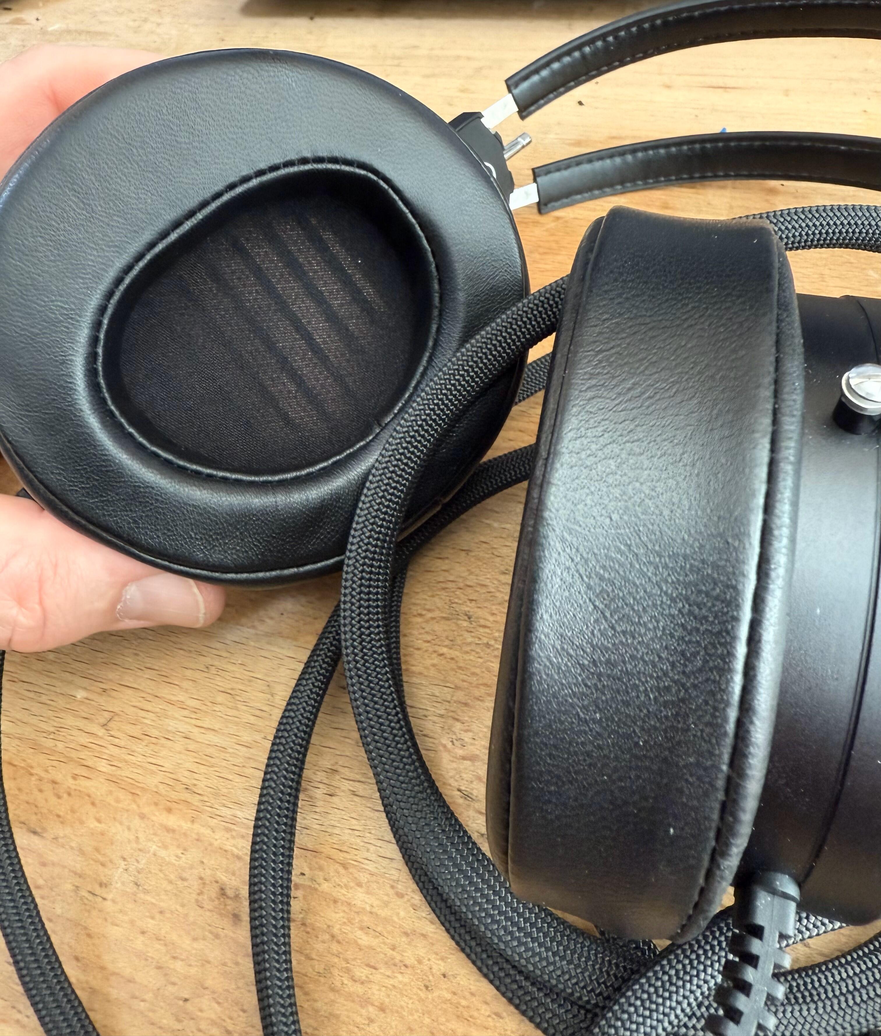
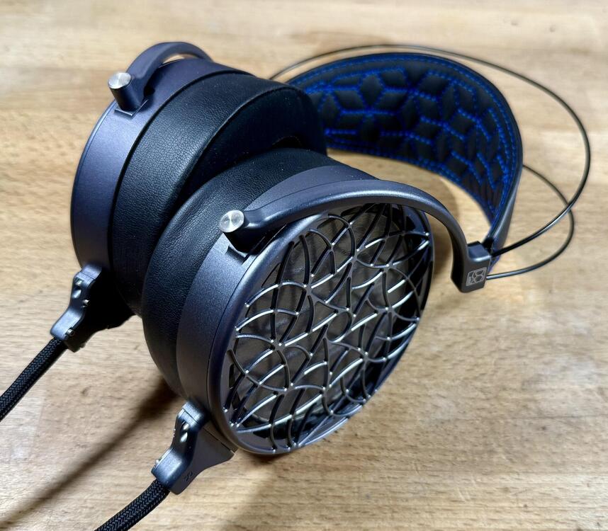
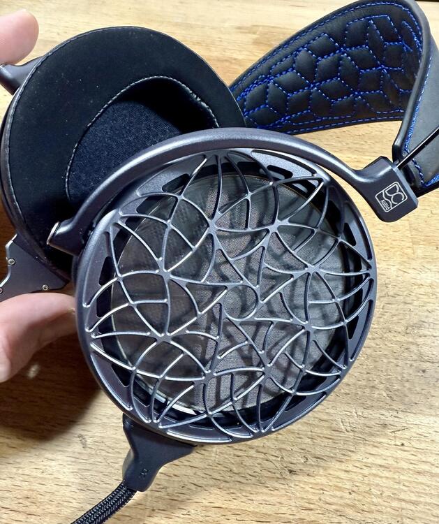
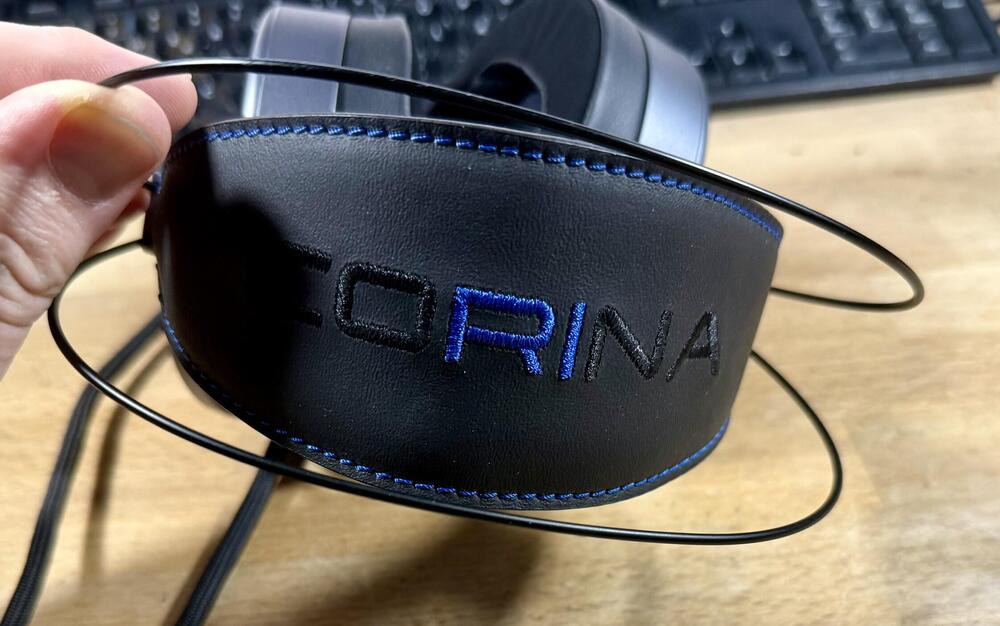
Now that the prices of used Corina's seem to be crashing hard, I picked one up. I have the impulse control of a fly when it comes to electrostatic headphones but this set was like new and way less than half price... Overall impressions match those from when I tried them at CanJam NYC in 2023, some parts look great while others feel like a 100$ "GAMING!!!" set for ROG or Razer. The housing is well made and I do like that back design. The headband is utter trash, the earpads feel high quality - yet at the same time extremely cheap and that blue stitching... who signed off on this? Worst yet... what the fuck is this?? I will refer to these in the future as "coRRRRRRRÍÍÍÍÍna". Seriously though, why? This horribly offends my nordic sensibilities. Last year I've also picked up a used Voce, a set I hated when they came out. Put those stock earpads trash where they belong, fit the angled Ether pads and they are quite enjoyable. They are also touching 1k$ in terms of price so for that money, they are a nice set to have. Voce naturally had the same issue as the Corííííína, DCA always has the worst headphone boxes ever. They keep trying to make headphone stands in boxes which make no sense. Now for the sound... I just don't understand why these were made like this. They are like the headphones for people who hate how electrostatics sound. Do you like your headphones to sound expansive with a nice solid soundstage which goes outside of the head? Nope, you can't get that here. On some tracks they are simply claustrophobic, almost if you are listening through thick cloth. Sure, it sounds inoffensive compared to something super forward like the X9000 but compared to something voiced correctly... yeah it isn't great. ere we can see the culprits, mesh on the back on the driver and that stupid damping they put on the earpad side (faint circular holes through the earpad mesh): Why they did this, I haven't got a clue. Electrostatics don't need this level of damping so it could only damage the sound. The Voce was initially supplied with a bunch of damping pads to put inside the earpads so they might think this is necessary... I didn't find an easy way of opening the headphones to check if this could all be removed easily. Now we come to the major issue though... what all this damping does to the midrange. Now this is really compounded by two parts, first off the headphones are rather inefficient and they sound so fucking dull. That means the volume has to be pushed to try and get something out of them... and that's were nasty midrange artifacts pop up. I picked up on some of this at Canjam NYC'23 but in my own system this is very apparent. It gets worse and worse, the more you push them which only goes to show how bad the driver setup really is. That also means I turn down the volume so now they just sound dull, not involving and I wonder why I'm not listening to something else. Now rant over, would I recommend these? Nope... not a chance, even at half price they are horribly overpriced for the performance they offer. On my desk now is the ES Lab ES-2a and the Audeze CRBN2 and I kept wondering why I wasn't listening to either of them instead. The Corina isn't even comfortable so yeah... nothing going for it really.
-
-
I lumped them all in together but they are all utterly overpriced with crap performance. The Sr. just baffles me, how anybody could say they are high end. I spent 5 minutes with them and they are so utterly unremarkable and outclassed by pretty much everything at 1/10th the price. Jr. would be okey at a much lower price, with a better cable and earpads but still only Koss ESP950 level of performance. Both also suffer from a fatal flaw which will likely kill all of them, the drivers oxidize. Jade and Mini are the same thing really and again... I'd take a Koss ESP950 over them with better earpads.
-
Yes, the Shangri-La Jr. is trash. It is just a slightly warmed over Jade with a worse headband and all the same issues. There is no proper baffle seal on them so it is as if the sound just hangs there, just so ever slightly out of reach. Very much lacking in engagement and any real presence. If it were 500$ or less, might have some slight merit but at the current price you can do so much better. The EX-1a is for instance at a similar price point and difference in sound quality and build is miles apart. I've been spending a lot of time with them over the weekend (as the next big purchase is incoming today... ) and they are excellent. The headband isn't exactly comfy but as a homage to the older Stax style (similar to the SR-X1) they succeed nicely. They don't have the bass of the ES-2a due to the much smaller drivers, but at not lacking in anyway. Similar, slightly laid back, presentation and far more neutral than any of the recent Stax stuff. The closest set that springs to mind was a few sets of Pro bias SR-5's I built years with Gamma Pro drivers. Excellent extension, very good midrange and an ever so slightly euphonic sound signature. The Stax SR-X1 goes after that same sound signature but the EX-1a just does it better.
-
It is the same exact procedure as in any other Stax amp. The 717 has a servo though, which monitors the output, and kills it if the offset is too high. If it was cutting in around 0VDC then something is very wrong with either the servo or the amp. Ideally you'd test the amp and adjust from the outputs of the amplifier, before it hits the output relay.
-
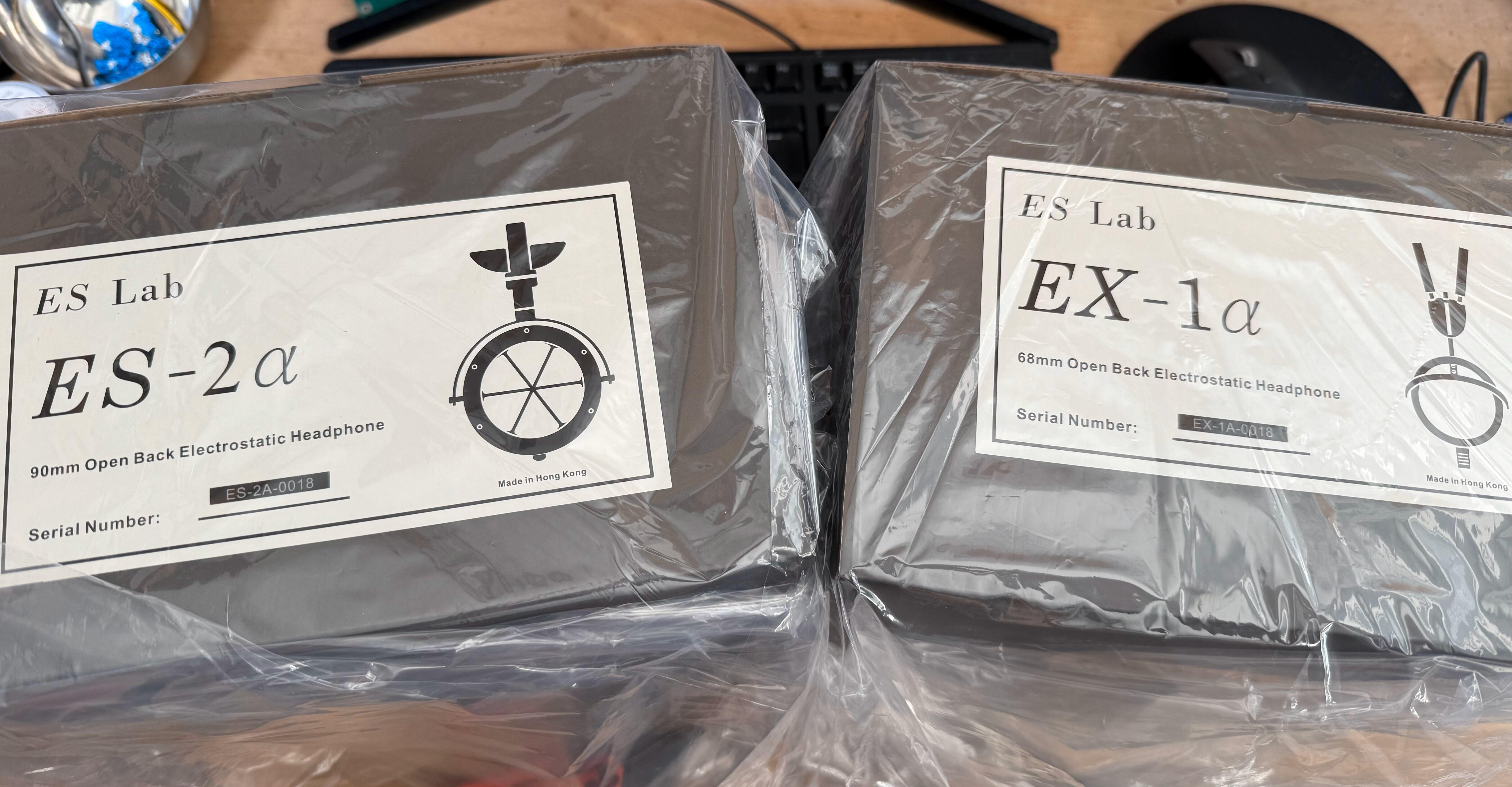
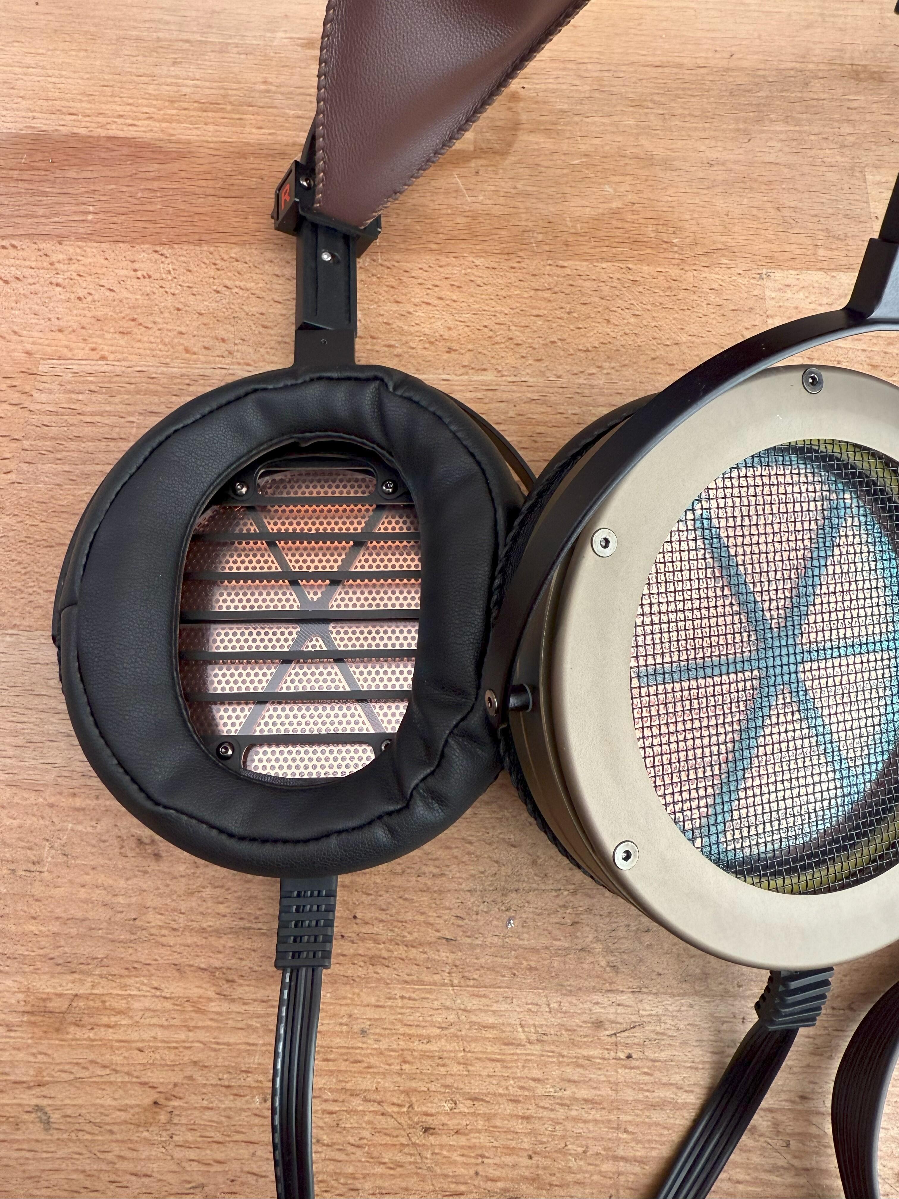
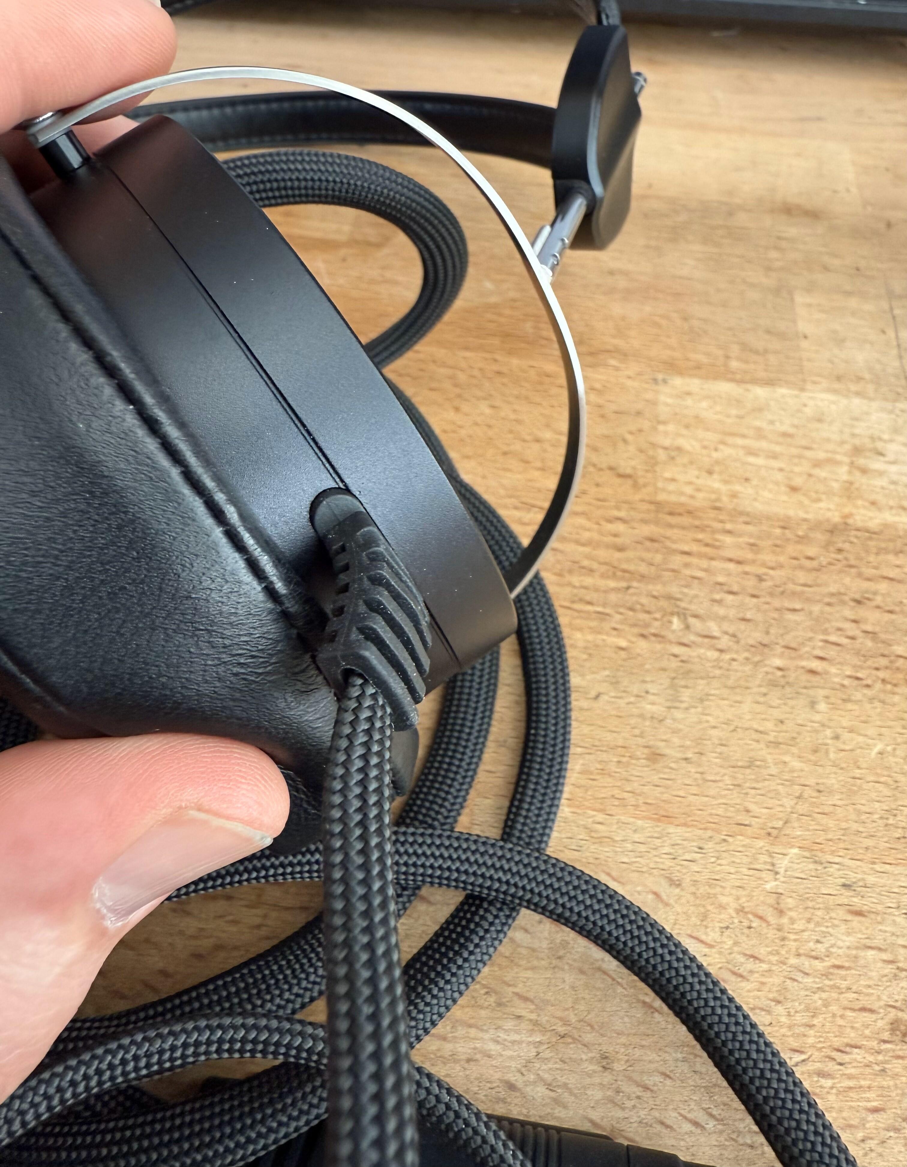
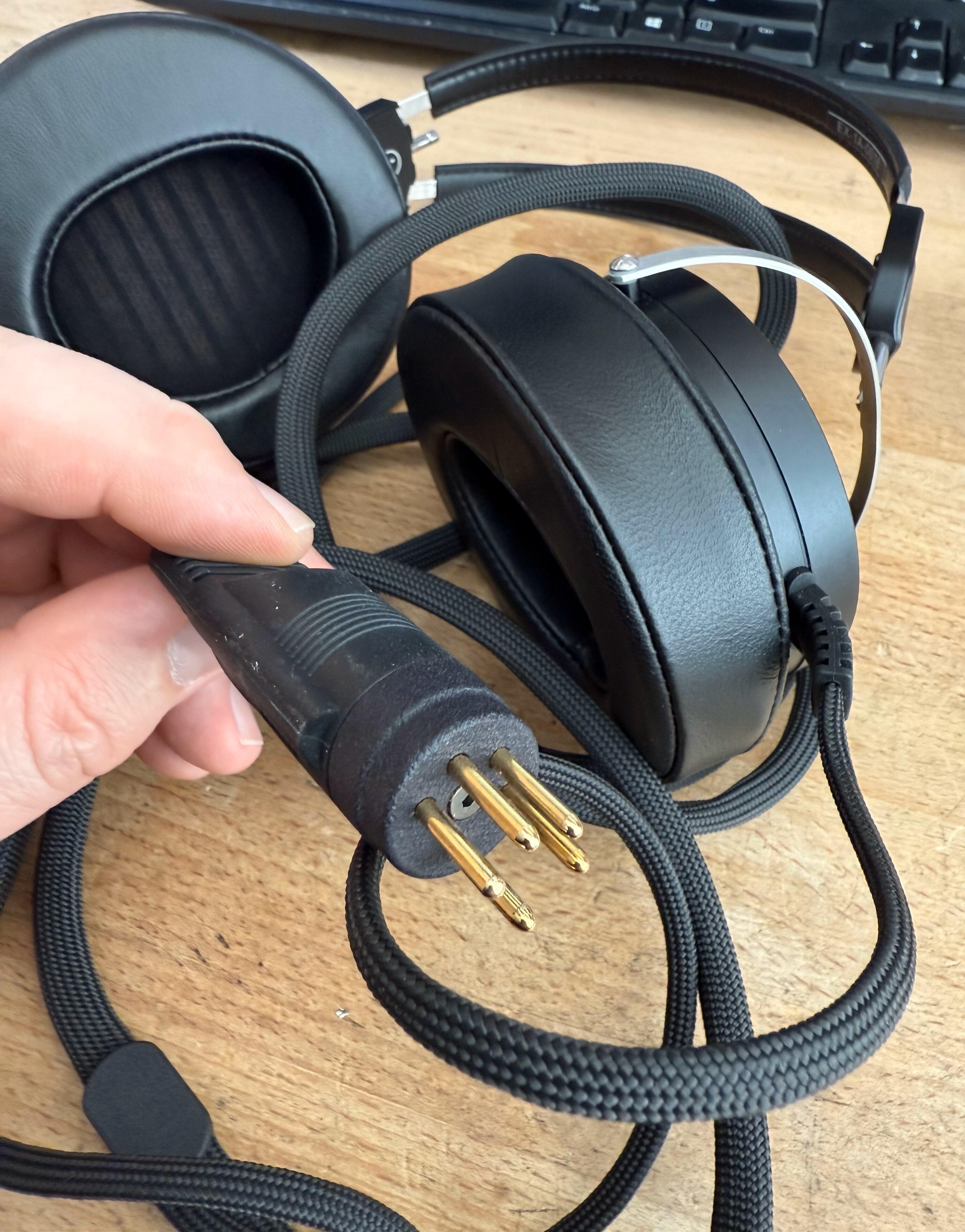
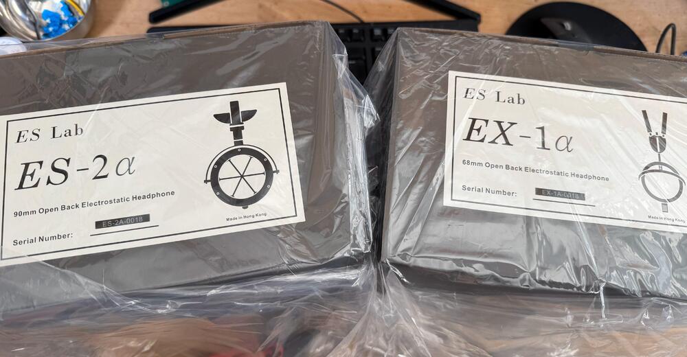
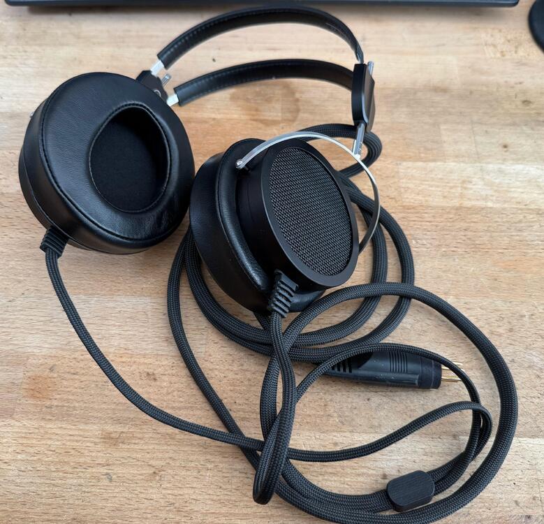
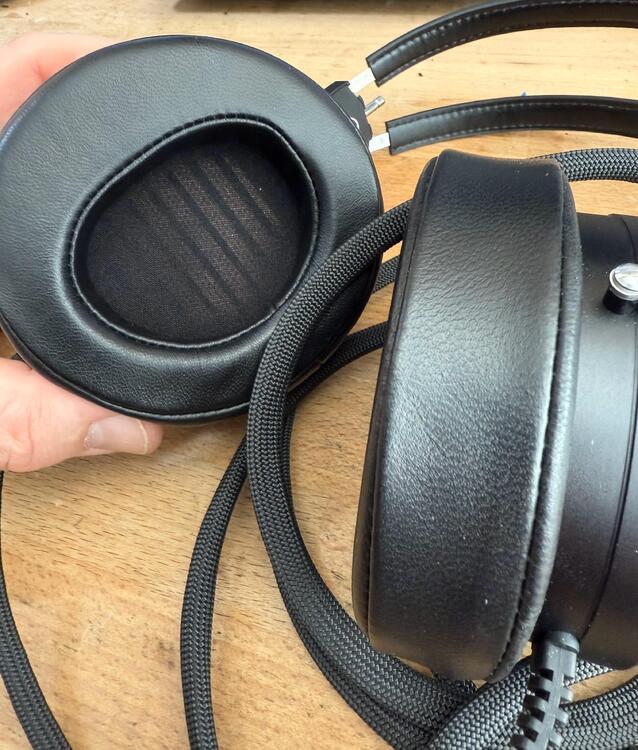
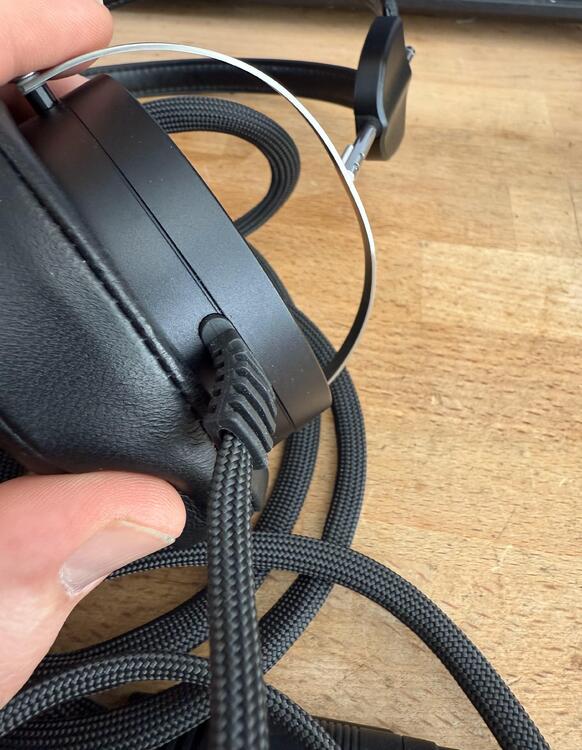
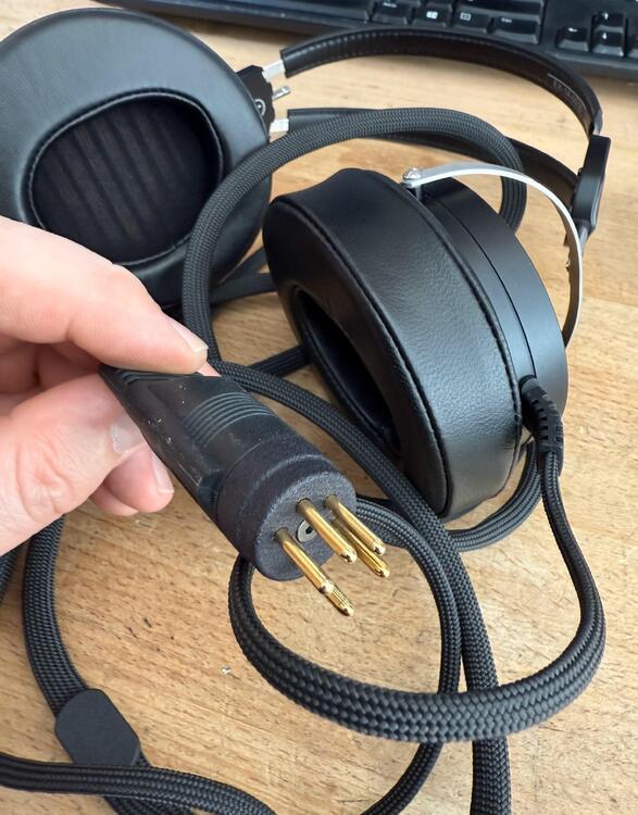
Here I was thinking I was going to have a productive day... I didn't take any pics of the wooden boxes but they are very nice though my EX-1a box was branded as ES-2a... no matter. First off is the ES-2a and I went for the "Omega look" in terms of color. My ES-1a is all black so made sense to separate them in the collection. I like the color a lot, the finish isn't quite perfect but having been through the hell of trying to get perfect anodizing... yeah I understand that. I'm happy the outer screen has mesh in it now as that's a large part of why the Omegas sound the way they do, not that this is a copy of the Omega. I mean not really... The earpads are very nice and supple, concave similar to the newer Audeze LCD pads. A closer look at the driver face and those lover copper stators. The dust covers come with the set and I did install them as I like to keep dust out of all of my headphones. Might have some slight impact on the sound but who cares. I ordered the set with the regular cable but Benson upgraded me to the Stax Wide PC-OCC cable free of charge so thanks for that. The fit and finish of these is excellent, better than the ES-1a and that was no slouch. My main issue with them was the lack of strain relief on the headphones for the cable but that has been fixed here. EX-1a: I was pleasantly surprised when Benson told me that there would also be a cheaper version coming in the form of the EX-1a as ~1k$ headphones are sorely needed. Clearly been in the works long before Stax introduced the X1 but a take on the same Stax SR-1/2/3/3N/5/5N and X design but with much better build quality than the X1. The earcups are actually fixed to the headband and made of aluminum, not needing the new Stax mod of placing some tape over the X1 forks on new units as they won't stay in place. Very nice, all leather, earpads and it looks like leather on the headband as well. Very nice cable entry, made of soft "rubber like" material. Same plug on both sets (this has the basic 6core cable which seems to be perfectly serviceable but more on that when I get some time with them) and it is a mixture of the same rubber-like material and 3D printed end piece. Works perfectly. Now for some impressions. I've just about had an hour since I got them and spent it on the ES-2a and all I can say is... I've very, very impressed. Very neutral sound signature, a bit laid back (as if you are a couple of rows back from the performance) with a large and expansive soundstage. No lack of focus here though, they conjure a very solid stage but it's just a step back from say a 007. Very Omega like really... Treble is nice and extended, not the mess of the Stax 009 and X9000, just as detailed though . Midrange is excellent, voices have the right presence without being too forward. The bass is tight and deep, only small issue I've found would be a bit of a lack of extreme deep bass and some slight resonance in the bass on certain tracks. Nothing I worry about and I'd take these over the Stax 009's or X9000 any day of the week. I'll try the EX-1a when I can take these off my head dig my only working X1 out of storage to compare against it.
-
Looks like Koss ESP/6's in the last pick
-
Yes, they did. No idea why as it makes no sense but is a trend with recent Stax designs.
-
Thanks for the post and lots to unpack here. The issue with using lower bias is less potential on the diaphragm and it has to be compensated to a degree with the drive voltages. That really doesn't work so it opens up a can of worms with regards to peaks and spikes making it onto the drivers, causing damage. It's all about balance. For me, 1uf caps are also way too big for what is supposed to be a high impedance circuit. I'd then put a large value resistor between them and a much smaller cap before the ballast to limit energy transfer. The choice of a Villard voltage doubler puzzles me as it is a terrible circuit with no real redeeming factors while it would cost next to nothing (even less) to use a far better circuit. I'd be less worried about switching noise in the diodes etc. over what it is a bad circuit. Smaller caps with cheaper diodes would work much better. The bias is also summed so any benefits from channel seperation are along gone. One the Stax SB units they took took one AC line from each of the channels to grab the highest potential as the impedance of the transformer would minimize any channel cross talk. Thanks for the offer but I don't need anymore stuff. I like the price and some of the ideas here but I'd switch to a better bias supply, maybe even a voltage tripler, with smaller caps and say a 200V limit on the input.
-
I have so many questions... why is the max bias 240V and why is there a separate 1uf cap for each channel? The bias on Pro headphones is shared for both channels... so is this a normal bias only unit? The specs list a 303 though so I'm confused.
-
All of that circuit is wrong so use that transformer and use the Stax circuit as found in the 007t or 717. The schematic for the 007t is certainly out there. Also, don't use caps larger than 100nf as that is plenty of storage for a bias circuit. Stax use 10nf so that works just fine. 1uf or higher is utter madness.
-
This bias supply will blow up your headphones very quickly so don't use it. Everything is wrong with it so I'd completely scrap it
-
You think those are output protection resistors... on half of the signal? Yup, makes sense. Notice the cap there, with the resistor? Might that be a fucking RC network?
-
You said they would serve no purpose, that is clearly wrong. Stax never put any protection resistors in any SRD unit (or anything else for that matter) as they weren't introduced until 1994 with the T2. I don't need to enlighten you about shit but I will call out stupidity when I see it.
-
The 5k1 output resistors are very much necessary, you clearly have no idea why they are there.