-
Posts
14,519 -
Joined
-
Last visited
-
Days Won
23
Content Type
Profiles
Forums
Events
Everything posted by spritzer
-
It's been a month but the CRBN is finally here, well this is actually the second set I've received. First set was one of two units to have an assembly issue which Audeze have now identified and fixed. I sent that one back and they sent a new one out. Now these are loaner sets but if I want to keep it, I will buy it. Just wanted to make that clear as I always own everything I tear down. The first set was setup to make it easier for me to take a peek inside so the pics I'll post later, will be of that unit. They are identical though and to say the CRBN looks gorgeous... well that would be an understatement. First thing that came to my mind when lifting out of the sturdy aluminum flight case, was a comparison to the Hifiman Shangri-la jr. Similar price range (I paid 4000$ for my set back in the day) and by comparison the Shangri-la looks like a 200$ Aliexpress special. The carbon fiber headband, the forged carbon earcups and nice thick leather earpads. Yeah, this is for sure no Hifiman product and it really puts Stax to shame with their shitty SR-009 headband design. Not that I was expecting anything less from Audeze but the attention to detail is nothing short of exemplary. Nice long strain relief on the cables as they enter the cups, the quality of the Stax plug, the sheer comfort of having these on the head (even with my melon of cranium) and the list goes on. The only issue I could find with them (and it was true of both sets) is a rather strong chemical smell as they are fresh out of the box. It doesn't bother me at all but it might bother some so best mention it. In terms of amp requirements, they are rather power hungry. It was a clear design choice to make them a bit less sensitive so the amps need to be pushed further in terms of volume level but it's nothing extreme. I had a KGSSHV in my system when the first unit arrived so I kept that to compare against the new one. It drives them just fine but the Carbon is a better choice with roughly 4 times the power. I would place the KGSSHV/KGST as the baseline for them to get excellent performance and it only gets better from there. Now it's been only been an hour or so with this second set (a few days with the first one) so it's early but first impressions are great. To keep it short, it's what the Sennheiser HE90 could have been but never managed to do. The CRBN has that same ethereal, diffused quality but with far more midbass and bass presence. They are not the bass monsters which the 007's can be but there is enough there and they are not bright or forward sounding at all. I'll post some more impressions later and the teardown pics as well.
- 120 replies
-
- 27
-

-

-
It's always great to have new sets to play with but the recent Stax sets have just been such a massive letdown. The 009BK is the only one of the recent sets I've actually kept but that's more down to me needing to have a set of 009's rather than using them for fun. The 009S is such a disappointment... Speaking of the CRBN... I'll be posting about that soon as I have them sitting on my head right now... Ohhh and teardown pictures as well.
-
Yeah, the SRM-500t is the same amp as the SRM-006tS but the price is up by 35% or so, the SRM-400S is a far worse design than the SRM-353X and again, the price is up by 30-40%. Don't get me started on the SRM-700 amps...
-
That's probably the mesh stator but I have very little enthusiasm for this. All of the Stax prices are now nuts so this is probably going to be 10k$ or more.
-

JR Audio amplifiers aka zero fucks are given - caveat emptor
spritzer replied to spritzer's topic in Headphone Amplification
That looks like the paint failing and not the actual plastic? -

JR Audio amplifiers aka zero fucks are given - caveat emptor
spritzer replied to spritzer's topic in Headphone Amplification
It is a copy of the SR-Omega so it has all the same issues as the Omega... i.e. a headband which Stax should never have used for them. They break... a lot... and have since 1993. As for the ES-1a, i have been using my set pretty much daily for 18 months now and they are still perfect, no issues at all and always sitting on a Stax stand... even with a couple of tumbles to the floor as I pulled on the cable. -

JR Audio amplifiers aka zero fucks are given - caveat emptor
spritzer replied to spritzer's topic in Headphone Amplification
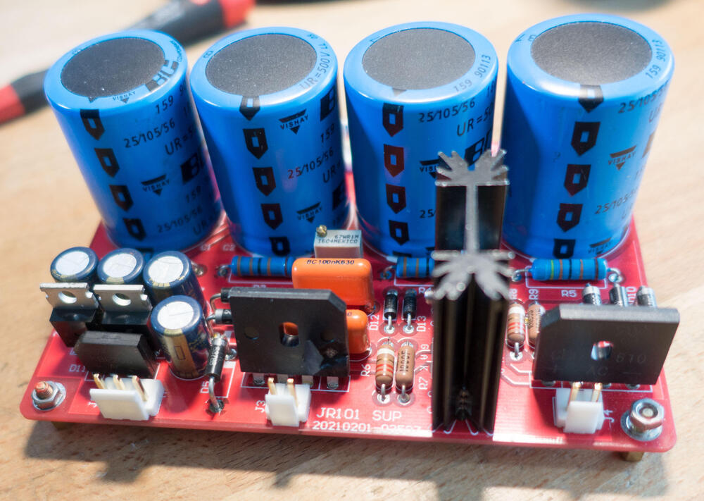
Some progress on my end, the amp is up and running now. It only took a new KGSSHV psu, new transformer, new power switch and I also swapped out the Stax socket as that nylon one just bugged me. I also dropped the voltage from +/-400V to +/-350V as hacking up the amplifier boards would have been a lot of work and the lower voltage negates most of that. Couple if funny things, the sheer number of misspellings on these boards is hilarious, bias is always written "Bisa" and look carefully at the text on those amp boards for some hilarity. One other thing, I was going over the PSU board and noticed one thing, the caps for the bias supply are 630V rated... now to generate the bias this is a voltage doubler, it takes the raw AC input (which is 325V or so) and doubles it. For that the parts need to be rated at least double the input voltage and guess what... 2*325V is more than 630V. That is assuming the line voltage remains stable and there are no spikes. Yeah everything done to save just a little bit of money. -

JR Audio amplifiers aka zero fucks are given - caveat emptor
spritzer replied to spritzer's topic in Headphone Amplification
If you want to let it go then I'd love to mess with it. Having these basket cases around is just so much fun... Something like that could work as a helping hand (similar to what we have in Spice and other simulation software) but it's no replacement for the human mind. The issue with everything is that building stuff (as in physical stuff) is hard and you run into issues that nobody thought of. One thing comes to mind, my very expensive office chair at home failed this week. It basically split in half where it was attached together with 4 M8 screws. Now they were large torx units and the head was only about 10mm in diameter and with the deep torx head, there was not a lot of material there to actually make the connection. Add to that they had not been properly tightened at the factory and bam... the heads broke off. If they had been torqued to spec then it would have been fine but just that little bit of play (plus I'm a mountain of a man ) was enough to make them fail. We've had similar stuff happen with the PCB's we've used and parts that should work just fine but are marginal. Then we have the issue that if you were to design like that, that means trusting datasheets etc. and well no... just no. -

JR Audio amplifiers aka zero fucks are given - caveat emptor
spritzer replied to spritzer's topic in Headphone Amplification
If you want to let it go, I'd love to take it off your hands. -

JR Audio amplifiers aka zero fucks are given - caveat emptor
spritzer replied to spritzer's topic in Headphone Amplification
I really need to find a McAlister amp for the collection.... 😉 -
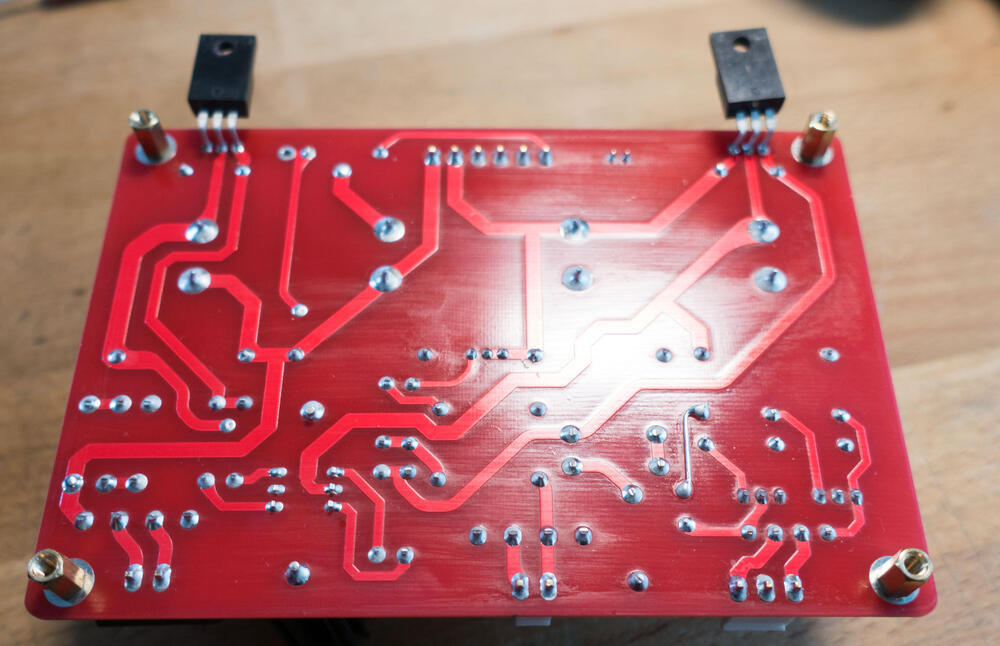
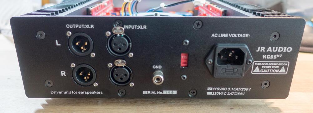
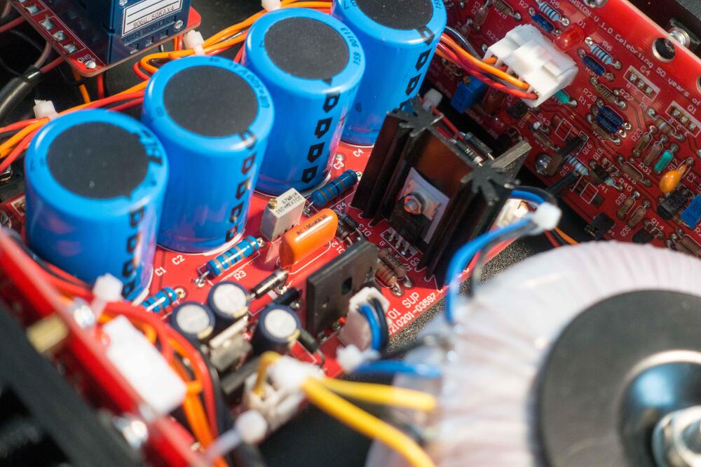
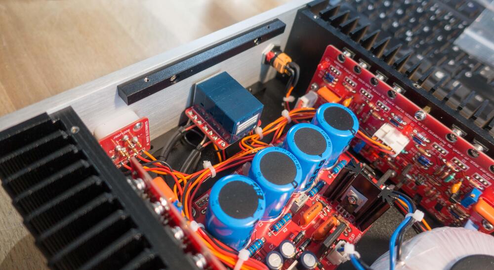
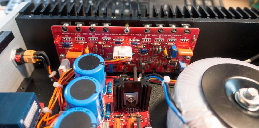
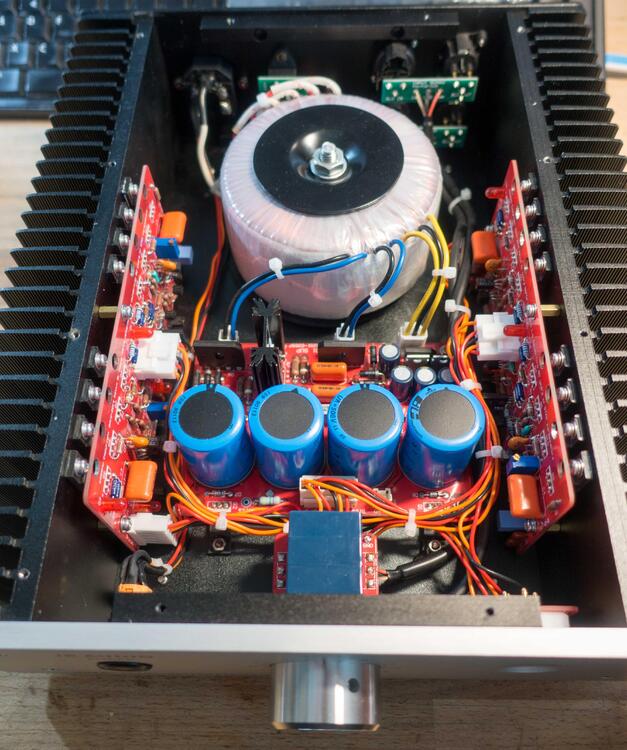
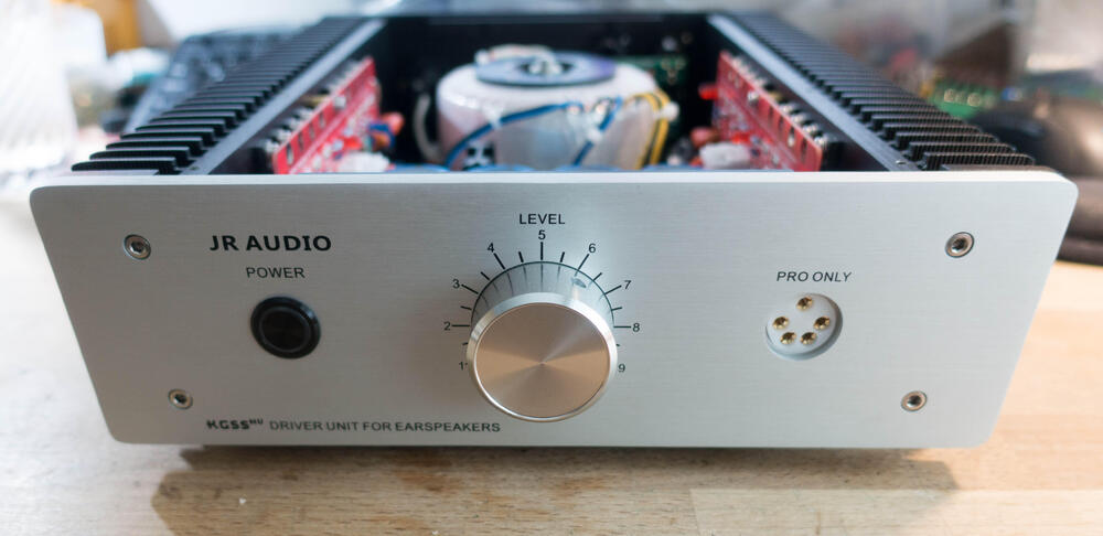
Here is something that has been cooking for a while but I've been just too busy to do anything about it. So JR Audio out of China have been building our amp designs for a while now and I started to hear horror stories almost immediately. They naturally have no right to use our designs and work in their crappy products but since when has that stopped anybody... I have been looking for one of these amps for a while now as I want to rip it apart and well... one owner contacted me. I'm going to ask him to come here and tell his story which is quite the tale. Let's just say Caveat emptor... So here is the amp and it arrived dead which will soon be clear. It is the KGSSHV version and well... it doesn't resemble my amp in any way... 🙄 One funny thing is that the Stax socket is made from nylon so the quality starts there. 😉 Nothing remarkable here but that voltage marking is directly lifted from my amps. Completely identical... Here is where I started laughing, this thing uses clone versions of old PCB's I made back in the day. The amplifier board (as can be seen by the date which they also copied) was in some of the older KGSSHV mini amp but this one is quite a bit bigger. Same goes for the PSU which was in the first KGSSHV minis but this one is 2.5cm wider and 1cm taller. All the components are in the same spots... it's just a bit bigger. Now here is whats wrong with it, see the bridge rectifier in the middle. That larger chunk of plastic shouldn't be sticking out of it. Here is one amplifier section and I just find it hilarious that they do a direct copy of my 7 year old PCB but manage to completely fuck it up while doing it. So all of those resistors are 1/4W units and that is a big no-no. Most are well shy of that power level (though not all) but the voltage ratings for many of those resistors is well below safe levels. It also annoys me (Kevin even more) that they have removed all values off the boards and replaced them with generic labels. We have always pushed for proper markings on all boards so they can be serviced at any time. Another thing clear in that picture are the 10M90's on that small heatsink on the PSU. They have a lot of voltage sitting on the metal tab so they naturally use a silpad and metal screw. Fucking amateur hour here. Another picture of the damage and one more of the underside: One nice attention to detail... or lack thereof is no thermal paste or silpad on the PSU pass transistors. Nothing at all and since the chassis is powerder coated, it has a hard time passing heat through the thin metal below. It's a shame I don't have any of these old PCB's in stock just to show how much of a blatant rip off they are. I'm tempted to order some (as I have the Gerbers for everything) just to show off what they are up to. Now what happens to this amp, well it belongs to me so I'm going throw out the PSU and the transformer plus replace all the necessary resistor on the amplifier boards to make this safe. Then I'll just keep it for shits and giggles. I'll update the thread when I do some more work on this clusterfuck.
-
I haven't had set for a couple of years now so I haven't played with them at all. I would also check the diodes in the SRD-5 as they can also be toast. As for the coating, just spray into the air and run the diaphragms through the mist. That is a good way to control how much goes on the film.
-
Those look great and reminded me to post this, a possible cable for DIY electrostatics: https://www.aliexpress.com/item/1005002121174291.html?spm=a2g0s.12269583.0.0.67082dbcJ5CL0I I just got some but have as of yet not done HV tests on it or anything but it's nice and supple, if a bit thin. Well worth a punt and reminds me of the Koss wire but not double insulated.
-
I do think electrostatics have a long way to go before we see anything resembling complete maturity. The issue is that very few are attempting TOTL units or any real improvements to the tech. Most are just a play on different tech already out there and with some hyperbole attached. The Hifiman units did nothing new, ditto on the Voce and the HE1 uses pretty much identical drivers to the HE90 but with that silly amp design. I also agree that going any thinner on the diaphragms will just cause issues with stability with zero gains. Stax figured that out in the 90's but seem to have forgotten it again... 😉
-
No tracking info yet so until then I can't say.
-

Fidelix Staccato Stax Solid State Driver
spritzer replied to astromaddie's topic in Headphone Amplification
It is also fairly low powered too, those transformers are just two 12VA units and with a resistor current source for the output... not a whole lot of potential. -

Fidelix Staccato Stax Solid State Driver
spritzer replied to astromaddie's topic in Headphone Amplification
It is very much a rehash of older designs and nothing unique there. The "special bias supply" also doesn't hold a lot of water but good for them to get somebody to give them a patent on something nobody cares about. In terms of performance this is worse than the new SRM-400S for a lot more...and the 400S is a pretty crummy amplifier. A huge step back for Stax in performance. -
There has only ever been one MRI designed electrostatic that I know of, the Koss ESP900 which is just a 950 with a closed housing. I've heard that HE60's were used for this but never seen anything in the flesh, plus the HE60 headband is magnetic (plus the screws) so something had to be done about that. The MRI's I've been in all had sound pipes for the audio, simple tubes with the transducers elsewhere and sounded terrible. The Voce and the Hifiman units were indeed unfortunate. The Voce is well built but sounds like crap (electrostatics are all about that vague sound and loose, uncontrolled bass... ) plus that stupid case they insisted on shipping with them. Now the Hifiman Shangr-la jr. sounded good but that build quality and silly price makes it a solid miss.
-

Repair and restoration of my STAX SRA-12S
spritzer replied to Quad's topic in Headphone Amplification
The PSU's are shared so that shouldn't be the issue but it can be anything, a marginal resistor, marginal transistor etc. etc. -
I should be getting one of these to try out soon and can't wait. It wasn't fun sitting out the press embargo... 😉 I would take those measurements with bags of salt given the amps used and the people doing the testing.
-

Repair and restoration of my STAX SRA-12S
spritzer replied to Quad's topic in Headphone Amplification
I would definitely swap out the rectifiers, they are really a wear item on anything this old. -

Repair and restoration of my STAX SRA-12S
spritzer replied to Quad's topic in Headphone Amplification
Voltage divider off the B+ works just fine and hum can be pretty much anything so impossible to tell. -
Indeed, that's and excellent way to fix it. If the elastic has stretched too much the same can be done by opening up one side and shortening the elastic.
-

Megatron Electrostatic Headphone Amplifier
spritzer replied to kevin gilmore's topic in Do It Yourself
This is very much the return of Singlehour, same utter incompetence and utter disregard for safety and the customer -

Megatron Electrostatic Headphone Amplifier
spritzer replied to kevin gilmore's topic in Do It Yourself
I'm not sure what those things are but they are sure as shit not Megatron's. Looks more like a SRX with some version of the Megatron output stage... This is why Kevin and I try to expose these fuckers as they are literally running away with peoples money. On a similar note, I have another amp from JR Audio here now and well... stay put for another horror story. That thing lasted for a few days before the PSU blew up... a sloppy clone of one of my old PSU's BTW.


