-
Posts
1,464 -
Joined
-
Last visited
-
Days Won
16
Content Type
Profiles
Forums
Events
Everything posted by JoaMat
-

and now for something completely different part 3
JoaMat replied to kevin gilmore's topic in Do It Yourself
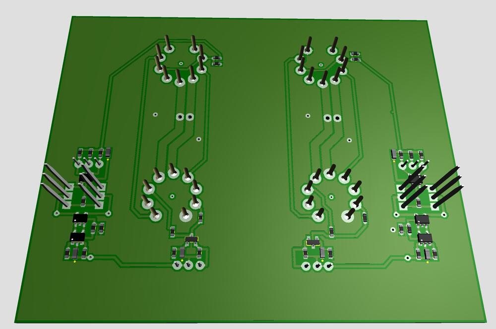
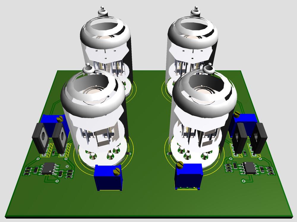
Inspired by Satyrnine's project and an attempt to recover from my Tube input CFA3smd failure some time ago I’ve been busy with this today. I call it Cascode Tube Input Something - intended for my CFA3smd something. +220/+15/-15V and filament needed. Based on ubaltoblatubeschem2, thank you Kevin. -
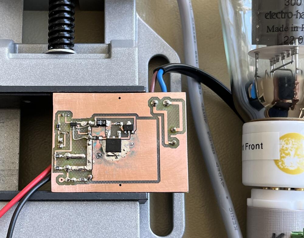
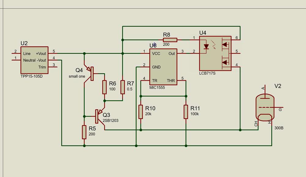
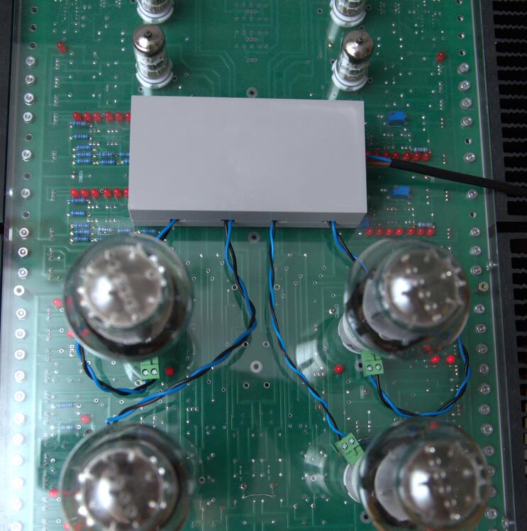
Now I think I’ve a 300B filament power unit I like. All smd on bottom side and common (through hole) trimmers and LEDs, and the Tracos of course on top side. With trimmers voltage at tube pins is easily set to 5.00 +/-0,05V. There is voltage drop cross wires and solid-state relays. Cover with ventilation slots. The Tracos produce some heat.
-
Yep, it seems to work. So far so good. No heat problems. Current set to 1.5A and when filament voltage reaches 3.7V solid state relay closes.
-

and now for something completely different part 3
JoaMat replied to kevin gilmore's topic in Do It Yourself
Take a look in the balanced headphone protector thread. Just a few pages and I think you might find something useful there. -
-
Soft start would be nice... …if it works. Not sure it will, but I know a way to find out. Above is based and inspired by this:
-

and now for something completely different part 3
JoaMat replied to kevin gilmore's topic in Do It Yourself
Never underestimate good old designs. -
-
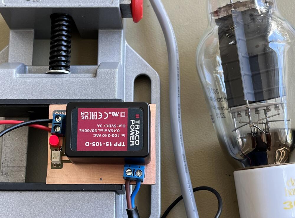
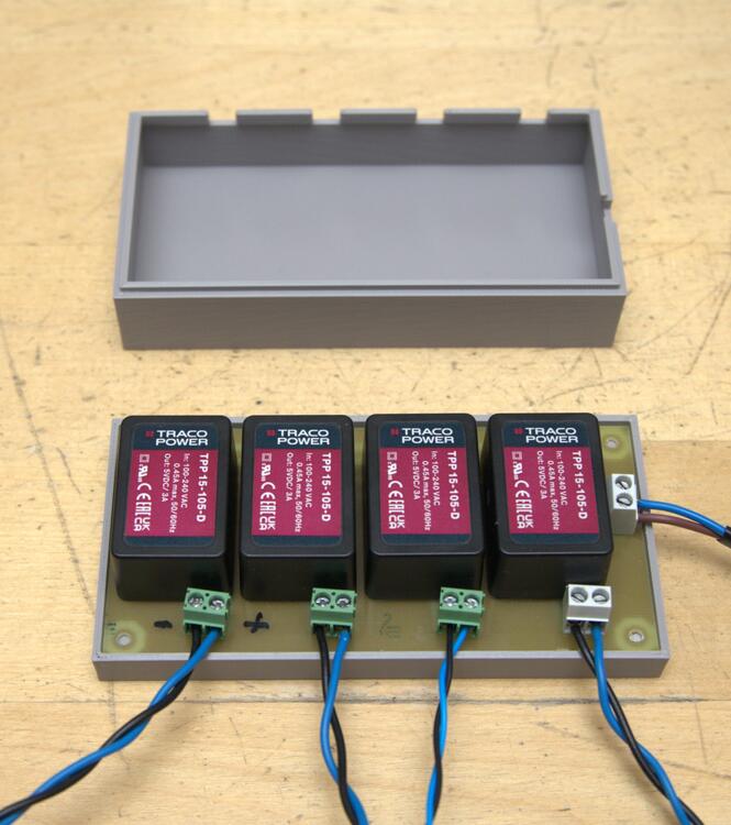
I 3D printed a cover to my filament power supply today. Just four Traco TPP 15-105-D and some tblocks. I don’t think my tubes need slow start – and if they do – they are not my tubes.
-
-
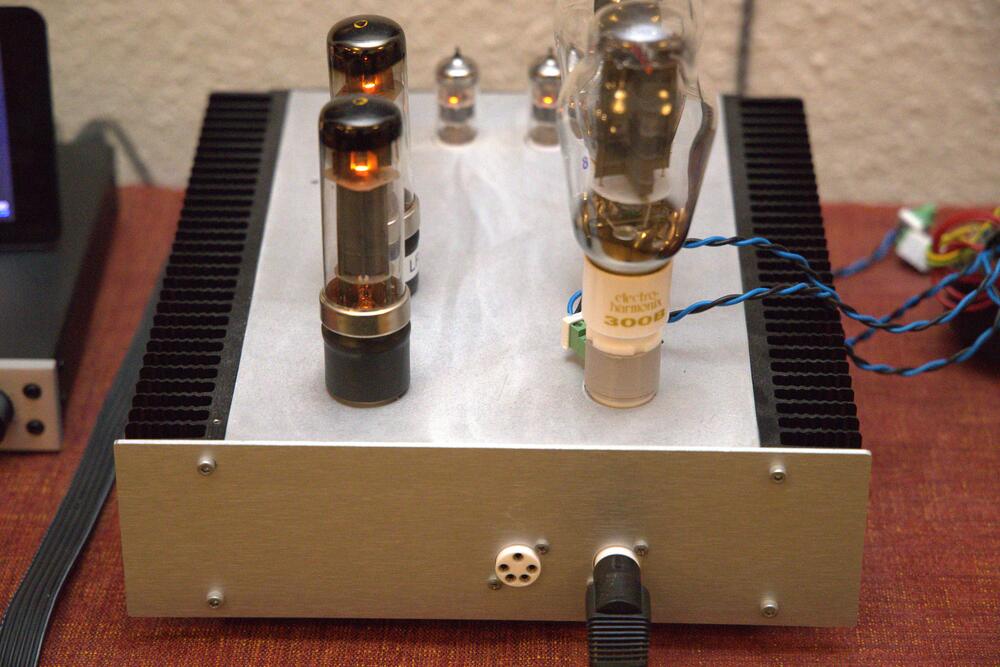
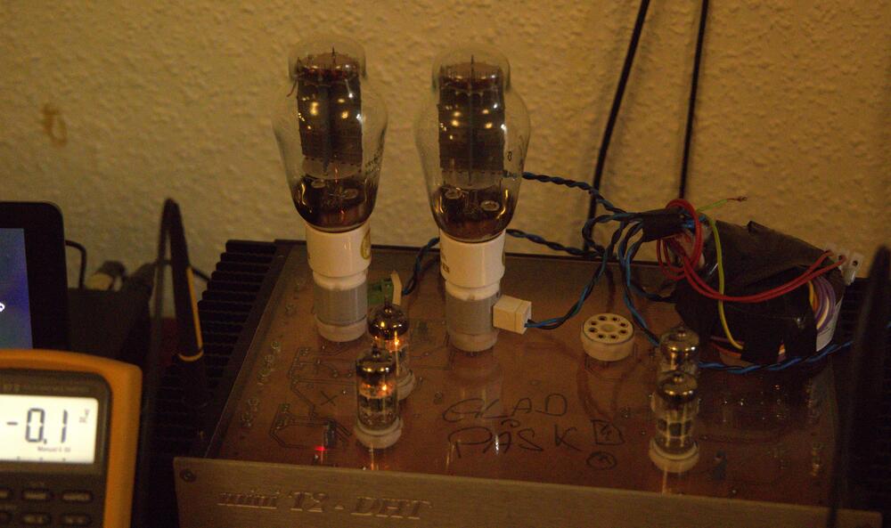
DIY T2 amplifier with 300B tubes. Amplifier is built on Kevin’s board. Only modification is decreased high voltages, +/-400V instead of +/-500V. Homemade 300B to EL34 adapters connected to four Traco 5V switched PS for filament power. I only replaced the EL34 with 300B along with the filament power supply. No other adjustments. It works – I’m in no harry to change back to EL34.
-
Wish you a very happy day.
-
Yes, they were new. Thanks for feedback.
-
Hum/noise disappeared after an hour. I’m a bit surprised but I can’t hear it any longer.
-
Think I prefer stereo. Moved the 300B to a T2. Left channel has EL61 with adapters from China and right side has 300B with homemade adapters. Works all right.
-
Happy Easter folks! Three months ago I bought a pair of Russian 300B. Intention was to try them in an electrostatic amplifier. Eventually I’ve put them in my DHT mini T2. Only mono version but it works. There is some unwanted hum/noise. Maybe because 5VAC for filament. I’ve DC alternatives, so future will tell if that might solve the issue. Anyhow, I’m enjoying the music (only left ear) and I still have some good stuff left.
-

and now for something completely different part 3
JoaMat replied to kevin gilmore's topic in Do It Yourself
Thanks simmconn. I think you are absolutely right about that trimmer. When working with my version of CFA3 I added a small trimmer to the lower current source (sink) to be able to, as you put it, balance the P and N arms of the input stage. I don’t remember my reasons to omit the 10K trimmer. But I made some simulations now in LTspice and they indicate that the trimmer changes the voltage cross 100K resistors with 0.1mV or so (but that is my simulations). -

and now for something completely different part 3
JoaMat replied to kevin gilmore's topic in Do It Yourself
I’m not sure of the purpose of the 10K trimmer. The two op amps control the outputs very well so I think you can set the trimmer to any position without noticing much. Anyhow, I omitted the trimmer along with the 10K resistor connected to trimmer center pin in my CFA3_something project. -

Megatron Electrostatic Headphone Amplifier
JoaMat replied to kevin gilmore's topic in Do It Yourself
Maybe one can feed heater direct from the Traco? A small test showed that current starts at 4.2A, decreases below 3A in 2 – 3 seconds and below 1.5A after another 3 - 4 seconds. Tested both a EML 20B-V4 and a 300B. From Traco datasheet: Output Current Limitation 120 - 200% of Iout max. 145% typ. of Iout max. -
I think 2sa1627 will work. Someone have to test it. Let us know how it turns out.
-

Megatron Electrostatic Headphone Amplifier
JoaMat replied to kevin gilmore's topic in Do It Yourself
but you have connected negative traces to trim pin on layout above... or am I just confused? -

Megatron Electrostatic Headphone Amplifier
JoaMat replied to kevin gilmore's topic in Do It Yourself
TTP15 pin 3 seems to be a trim pin. Can that pin be used for -Vout?


