-
Posts
1,464 -
Joined
-
Last visited
-
Days Won
16
Content Type
Profiles
Forums
Events
Everything posted by JoaMat
-
Splendid! Nice work indeed. I’ve a mill, but have to figure out how to make the model…
-
Yes, 10 volt is correct.
-
Probably because the 5V doesn’t like shunt mode. From LT1021 datasheet: Three voltages are available: 5V, 7V and 10V. The 7V and 10V units can be used as shunt regulators (two-terminal zeners) with the same precision characteristics as the three-terminal connection.
-
Transformers in the front (other reason than above though). You like the wiring? Size is huge. Angel brackets adds to much thermal resistance and add space.
-
Great! T2 current sources with c4686 instead of c3675?
-
Have you tried the opto servo?
-
-
Yep, that’s right. Tried to be smart. Set the cut depth to shallow at first. Ordered the machine to clean up a small area…. and at the same time it cut the trace near that pad. Learning by doing...
-
I agree with John. Amazing front plate you have done, Kerry. Today I built a T2 servo on a small board. It’s now doing service on an original DYI T2 and seems to work OK. If it really works the layout will be implemented in a new version of DIY T2. Also give me opportunity to learn milling PCBs on a small CNC machine – indeed a funny toy. Did a small mistake - can you find error in below pictures?
-
Don’t remember the exact words, but she is a very adorable partner. Got this as a present recently………
-
...fifty free hours, then
-
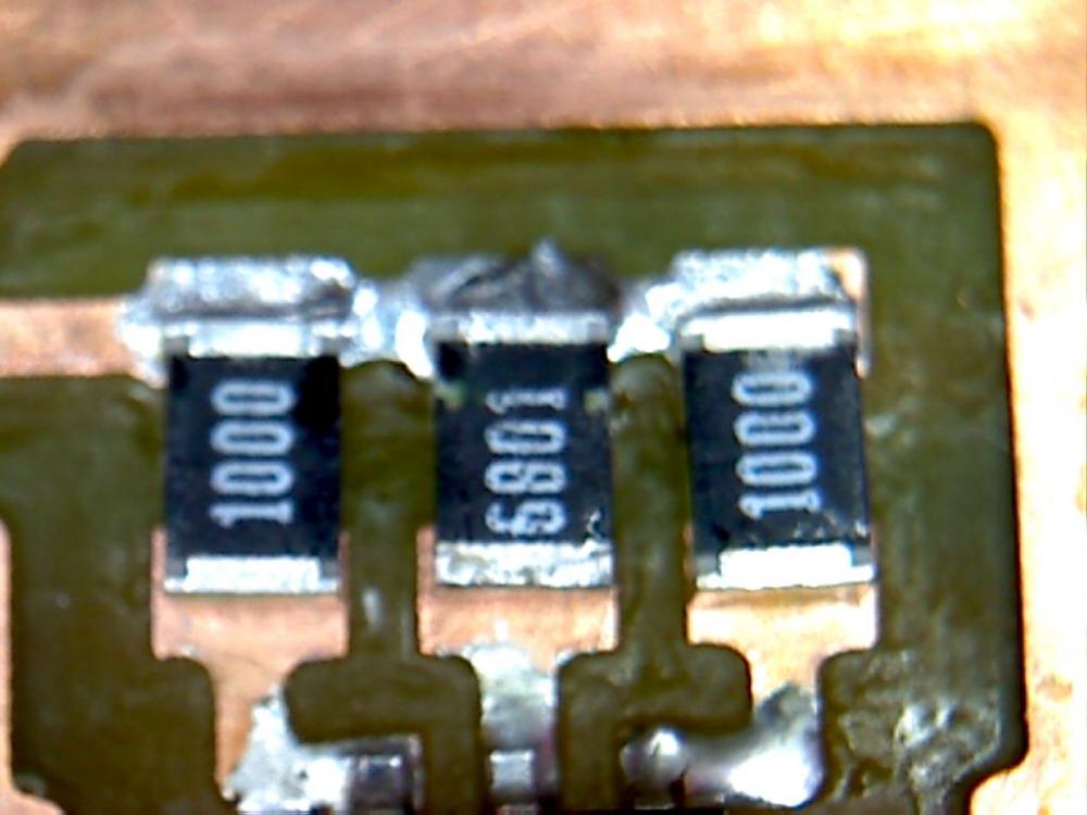
Last few days I’ve had some annoying noise from one channel of my Grounded Grid. After a few hours on surgery table I found this three small resistors…. …..obviously I missed solder them on both ends. I’ve used the amplifier like this for almost four weeks before the noise started.
-
Here is an original T2 with Kevin’s optocoupler servo. Servo is on a small board, replaces one of the 2SC3675 in Darlington pair. Works well…. so far.
-
With SiC I don't use any shoulder washer, just metal screw - torque set to 81 Ncm on the scale.
-
4180G
-
Looks insulated but bottom is not. I use aluminum oxide insulating washer and steel screw. Avoid conductive thermal grease.
-
If you use the correct shoulder washer and don't smear the junction with conductive thermal grease than it's safe to use steel screw.
-
Nicely done. That one is a small one. But else surface mount isn’t that difficult, with some practice…. and it's fun.
-
Once I cleaned a straight six BMW cylinder head in dishwasher. Very handy.
-
Anyone tried dishwasher?
-
Glad to hear it was that easy get rid of the oscillation. My idea is to build a version with ksa1220/ksc2690 replacing the old and hard to get mosfets. Have listen to an original DIY T2 with the mosfets replaced for a week. My impression is that it works well.
-
Good news. What was the problem and its solution? Might be valuable information for us.
-
This is my modified T2 from 2014. Later further modified with Cascaded CC a la JimL, replaced a bunch of to92 with small smd ants and replaced one battery with, an all SMD battery on a small daughter board. No oscillation, no hum or other issues. Works equally good as the three original T2s I’ve built. I frequently make layouts, mirrored or symmetrical and make the boards in our kitchen. For me it’s a hobby and I’m really enjoying it.
-
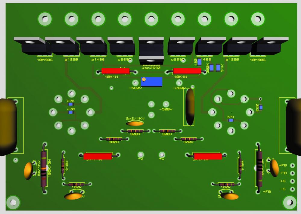
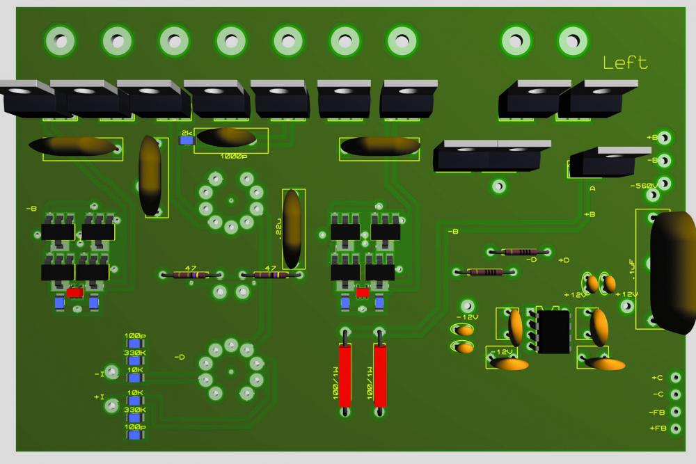
Did this last night, not finished yet. Modified T2 output section. All parts available at Mouser. SMD give space for bracket. Board size 150mm x 100mm. Darlington pair in the middle, one on heat sink and partner standing. Below: draft of an input board. Right/left channels will be mirrored.


