JoaMat
-
Posts
1,490 -
Joined
-
Last visited
-
Days Won
16
Content Type
Profiles
Forums
Events
Everything posted by JoaMat
-

Megatron Electrostatic Headphone Amplifier
JoaMat replied to kevin gilmore's topic in Do It Yourself
Megatron is probably 120 mA, that's plus 50 % compared to your Carbon. -
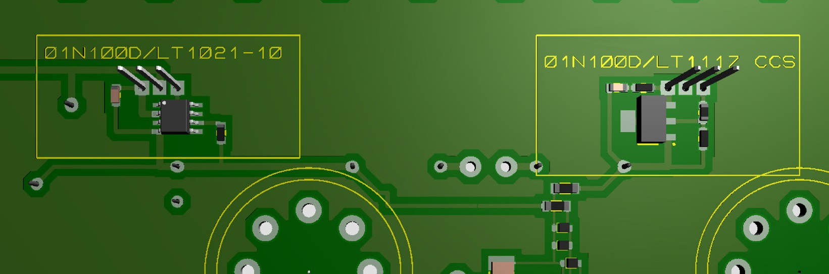
01N100D with LT1021 to the left. Got the idea from Kerry. LT3042 is a nice piece, but 1021 is a bit bigger and then easier to deal with.

-
emitter only needed during night and cloudy conditions?
-
Ops! Kevin pointed out the resistors in this post. Sorry.
-
Nice picture. If a1486 had been a kV device the T2 current source would be a better one? Most of the variation of the green curve must be due to the 150k resistors.
-
I do believe that the T2 current source is the one to aim for. But that’s only for the squirrels and the boys with big pockets filled with c4686. If you want a CCS based on components from Mouser or equivalent then I think 10m90s is good enough for most people, including myself. But we should look for alternatives for 10m90s so in that respect I’m grateful to Kerry’s work. I’ve had a T2 with c4686 and isolated switching power supplies for a while and I really like that amplifier. Probably the cascaded current source for driving the LED is preferred but I like the isolated things. Maybe I should try current source for driving LED, anyone have a schematic?
-
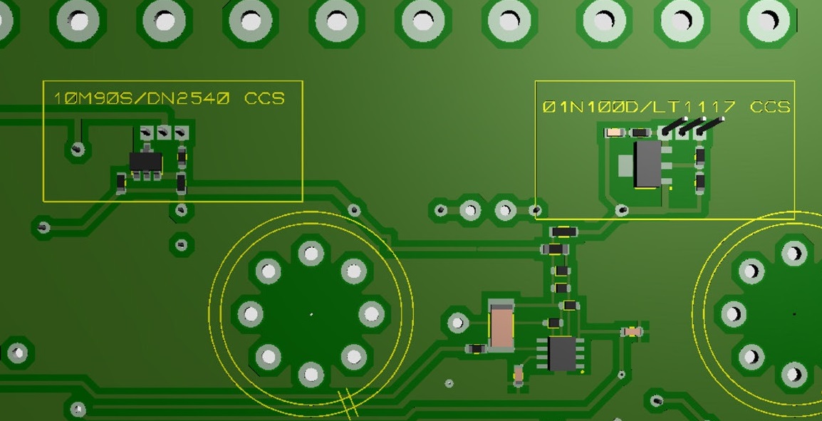
Two current sources. One “normal CCS” and one “Kerry’s in progress regulator CCS”.
-
Thank you, good to know.
-
Interesting current source. Would 01N100D/DN2540 cascoded work (in LTSpice)?
-
It seems that G3 is tied to the plate on kgsshvtubesandwich while G3 is tied to the cathode on BH and GG. Any particular reason?
-
Agree, very impressive. Can't be done much smaller.
-
It has been a rainy day so I modified the batteries on one channel. Replaced the four 2sa1486 with two 2sa1968. Battery voltage, offset and balance just fine but sonically I got unpleasant hum. Now everything is back with a1486. Why change something that works well?
-
Thanks a lot. Good to know I can save my small stock of 2sa1968 for more important missions.
-
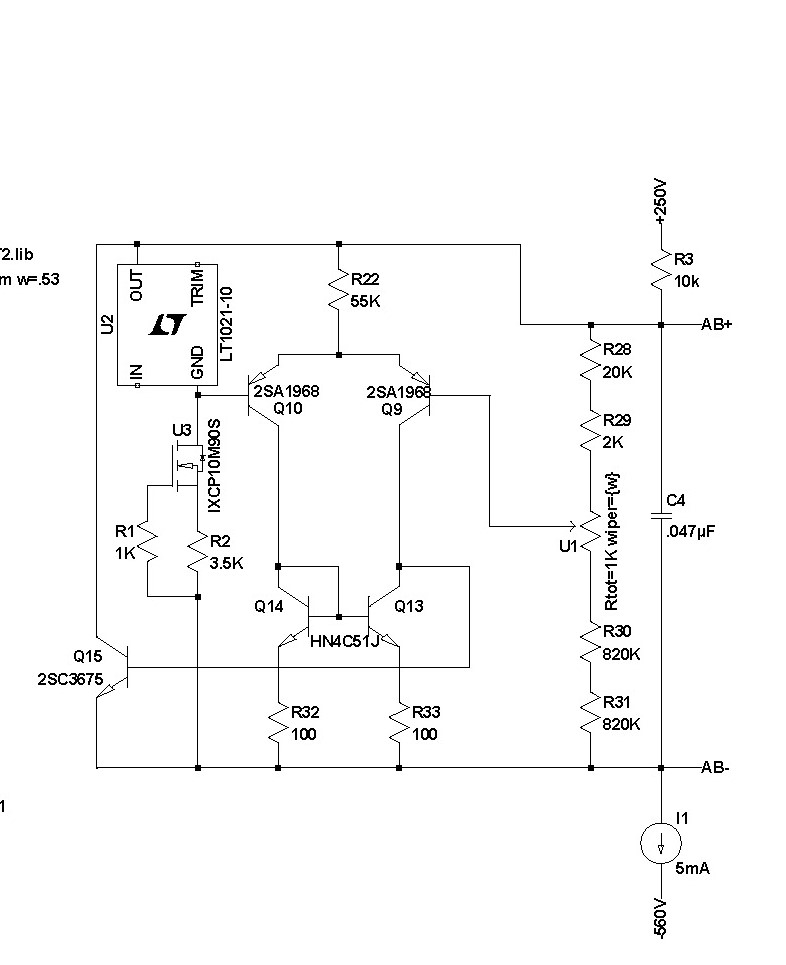
I've rebuilt a couple of batteries on original DIY T2 boards with LT1021 - works. Have looked for schematic without success but it is somewhere on my computer… Anyhow, how do you like this one: LT1021 current set to 1.2 mA. Hard to find 2SA1968 and easy to find smd HN4C51. Fewer components then the original battery. Better? probably not.
-
Thank you , Kerry. Added capacitance in feedback.. With 15pF the sine wave is replaced with something erratic - amplitude 100 to 200 mV. What is that compensation cap?
-
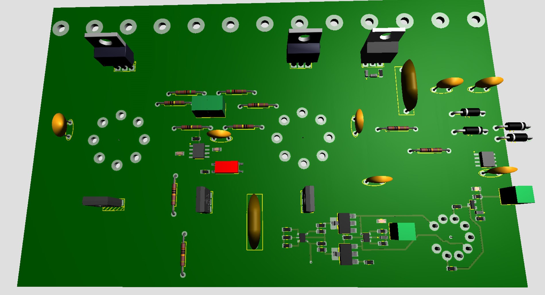
Thanks for the advice. It's one of the "original" DIY T2. Modified with something like Kevin's offset opto servo, DC/DC converter current sources and sj79 and sk216 replaced with BJT. After reading about s_r trouble with his T2 I checked my own with the scope and then I found the 750 kHz, 5 V amplitude sine wave. Despite the 750 kHz wave I'm very happy with how it sounds so I'm not in an hurry to try get rid of the oscillation…. Kind of work that can be very time consuming and boring. I've built three T2s with the "corrected" boards. Just put the right components it the right position, I don't elevate except power resistors. Power on, trim batteries to 740 volts and done. I don't think there is a board issue. All right, I've had problems but most of them have been builder induced.
-
I would suggest 5.1 ohm. Then you are good for approximately 120 mA, I think, which should be enough.
-
I just checked my T2 with an oscilloscope at outputs. 750 kHz, amplitude 5 V, nice sine wave. The amplifier is modified - offset servo and output current sources. I've no idea how to kill that oscillation. But that amplifier is the one I like best….
-
The solder resist - what stuff are you? From picture it seems like everything including solder pads are covered? Do you have to remove… before solder on component side?
-
The oscillation you have - is it only on one channel or both?
-
Megatron Electrostatic Headphone Amplifier
JoaMat replied to kevin gilmore's topic in Do It Yourself
I’m not sure that 3A per winding is optimal. You might end up with a voltage higher than 6.3 V if load is just one and a half ampere, but my knowledge on this subject is poor. Perhaps someone with better knowledge can tell? -
Megatron Electrostatic Headphone Amplifier
JoaMat replied to kevin gilmore's topic in Do It Yourself
Antek transformer is a good alternative but you might consider a custom made transformer. If you live in Europe – Toroidy is IMO a good alternative. -
Great, a new version of offset servo. I can’t remember how many versions we have seen so far, but as I remember one of the first was found in Kerry’s KGST (and Stax T2 of course).
-
So you don’t think I’m sleeping.
-
Happy Birthday!