JoaMat
-
Posts
1,470 -
Joined
-
Last visited
-
Days Won
16
Content Type
Profiles
Forums
Events
Everything posted by JoaMat
-
MINIWATT tubes - Nice!
-
Draft of dual 6922 input (similar to T2 input), with current tunnel (as Carbon etc.) Voltage cross 2sa1486 580V and 700mW of heat.

-
Kerry, do you hear any bump or whistle in the headphone when power off with the servo?
-
Make your pick. Then Whitigir build the other.
-
I suggest a Sandwich.
-
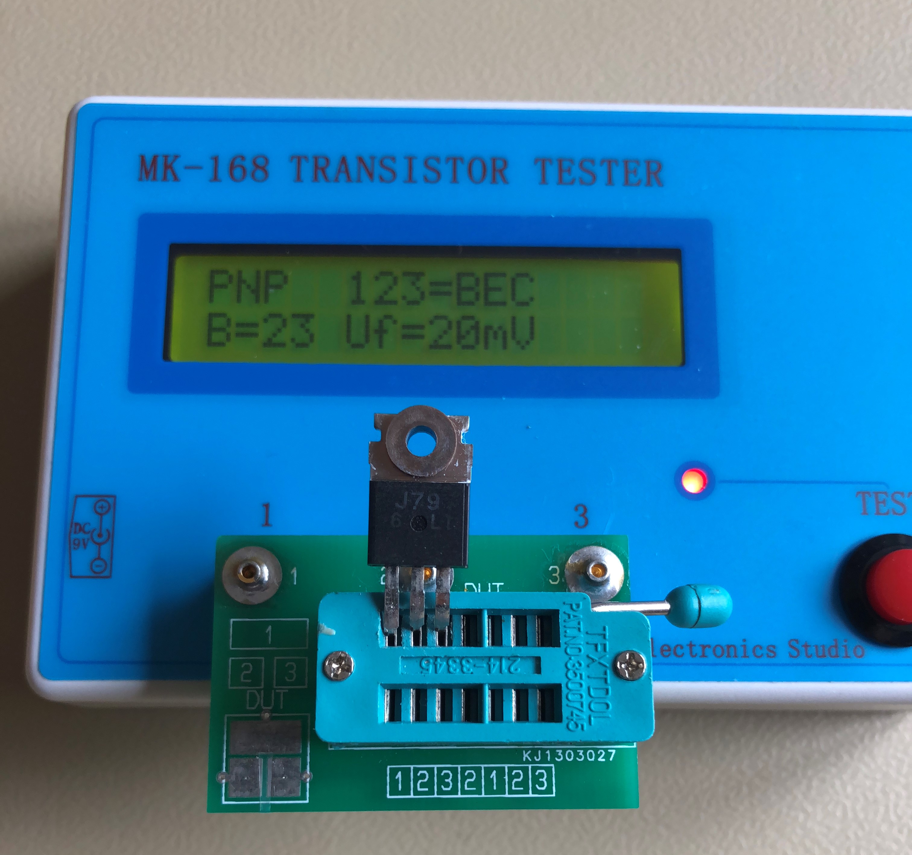
Suddenly left channel went down – turned out that one mosfet 2sj79 had transformed itself to a PNP.
-
Nice. Like the 08N100D up there. IC1 is?
-
Reduced voltage on my “modified” T2. DHT by night.
-
@@bui501, I’ve no idea if the PBHVs will do or not – someone should try. But how about KSA1156? Max voltage cross pnp in battery is around 370V. As for space it might be a little tight though. The squirrels sit on them.
-
Here is a link to a post. In that post there is a link to a BOM. In that BOM you find LTL-4213. I’ve two different BOMs on my computer from the same topic, both with LTL-4213.
-
The first electrostatic amplifier I built was the first version of KGSSHV with onboard heat sinks and I used LTL-4213 LED forward voltage 2.1V. At that time the suggested LED was LTL-4213 which also was used in the DIY T2. I’m aware of that some builders stick to LED with lower voltage. My experience is that you very well can use the “higher voltage” LED without changing resistors.
-
Voltage cross the resistor is LED voltage minus base-emitter voltage - roughly 1.9V – 0.6V = 1.3V. So approximately current through R33/Q17 2.5 mA (RV2 centered) and R50/Q20 4mA. Those values will depend on the individual components.
-
Very nice indeed! Like them Blue (Hawaii) lights.
-
1A at 450V – yeh, that’s a pretty decent load
-
Wow, that’s wonderful! U1 - op amp in sot23-5 package, any suggestion?
-
Yes, it’s the same SMD transistor. I just soldered them in standing to save space. As a DIYer you are entitled to do whatever you want. If going "through hole parts" I like that layout a lot. Then one should change 2sa79/2sk216 to ksa1229a/ksc2690c and make output stages cascode current sources. That would be a great amplifier with available parts at reasonable prices.
-
Yep, I remember you used a trimmer – that’s why I came to use trimmer on my modified T2. I think working voltage 50 V will do. Try the servo - it's easily done. Thanks Kerry, LTspice is really a very useful tool. I’ve deliberate skipped the D2 zener (Kevin uses the Zener) to see what happens and so far no failures. The R29 resistor is probably a good idea but I’ve skipped that too as the servo seems to work all right without it. As for C1 I use 1uF/50V in my Carbon and GG with tube input (same as Kevin later designs). But on the T2 I had some problem with 1uF so after some testing I ended up with 6.8uF (have just opened the amp to check). Regarding the 2.2pF – I actually added more capacitance to reduce some oscillation at outputs seen on the oscilloscope. I probably better go back and have look at it again. DIY is fun
-
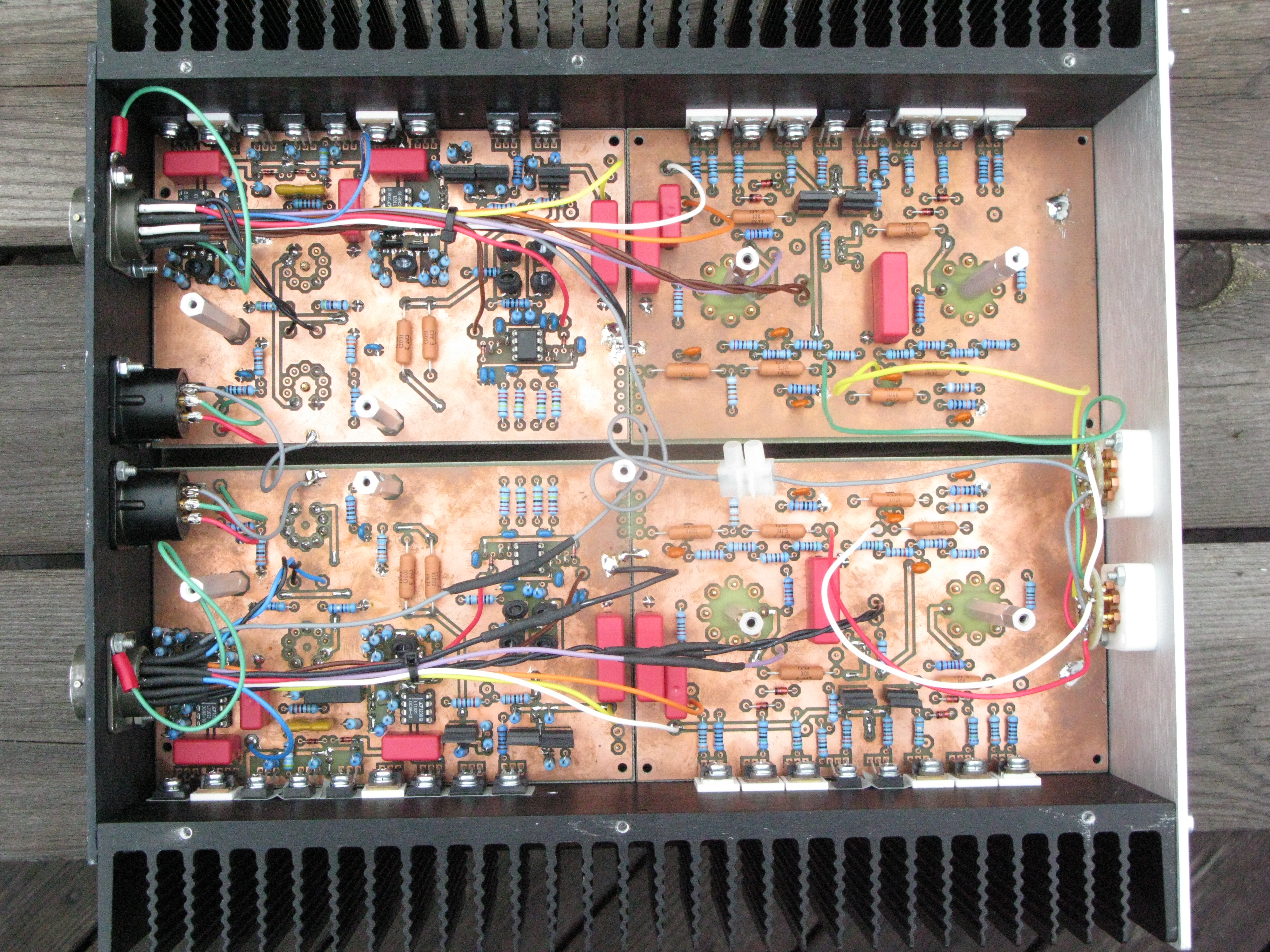
Below is a picture of my modified DIY T2. Zoom in and you can finds several resistors standing. There are also standing STN9360. You won’t find other types of STN9360. Those homemade boards have been in service for four years now. I’ve made several modifications and the boards have been very kind to me. Kevin’s t2shrinkedv10 is based on my home cooked boards. I’m confident his board is OK. But be aware if something goes wrong it could be a tricky thing working on that board as some areas are pretty crowded. Today I would make a different layout of the board as I find the board a bit obsolete.
-
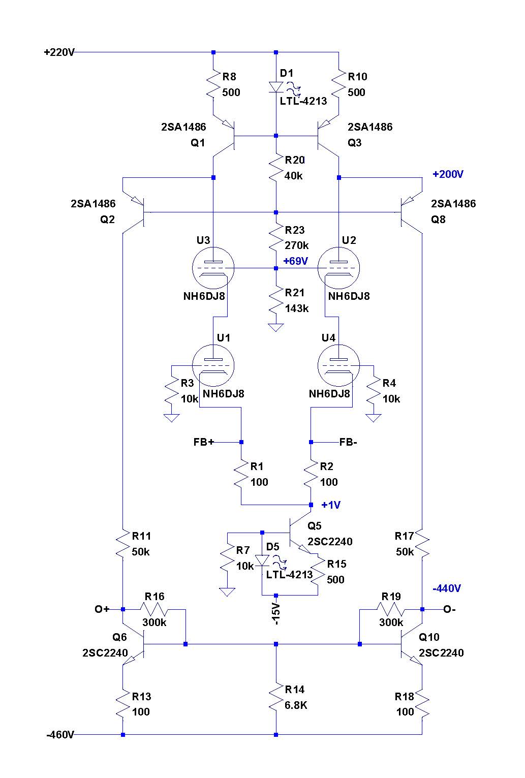
Above post show changes to the balance servo I’ve made. Below schematic shows changes made to get the KGOOS (Opto Offset Servo) - the only offset servo you need. Q33 and R73 replaced by a small daughter board and the resistor strings changed accordingly. For reference here is t2schemop.pdf, schematic of the STAX T2 output section. Drawn by Kevin Gilmore and redrawn by Linear.
-
I’ve two PSUs for my electrostatic amplifiers. The DIY T2 has 500 volts rails so I’m feeding all my amplifiers with 500 volts. Now I’ve been thinking of building a new PSU with 400 volts. From what I understand the only reason to go higher then 400 volts is if you really want high sound levels. Today I’ve brought down the T2 PSU to +/- 400 V and -460 V (the -560 V in my PSU is produced by its own regulator connected to ground). The only modification on T2 amplifier needed was to change the battery voltage from 740 V to 640 V – swapped the 4.7K resistors to 6.8K. Since I use offset servos similar to the opto servo Kevin introduced in his designs a couple of years ago I didn’t have to change anything else.
-
I’ve been using Denon SC-7000Z for several years and I would say it’s a great tool. With 1.5 mm tip it’s easy to remove a 5 terminal block or a small teflon tube socket. It can also be used as an “hot air gun” and then it’s very practical for desoldering surface mounted components. If interested check Howard Electronic Instruments – I buy spare parts from them.
-

Megatron Electrostatic Headphone Amplifier
JoaMat replied to kevin gilmore's topic in Do It Yourself
Two different types of EL34 in there? -
Electrokit is my favorite supplier – a small and friendly company. Just takes my 15 minutes by car.
-
Happy Birthday!
-
Below is from my kitchen today. I had to test if the DN2540 would do. 25 mA on the meter and voltage, from an old KGSSHV supply, is 887 volts. Only one half of Circlotron and the current seems to stable enough. Might be continued if I don’t break arms and legs during coming week down hill skiing.
- 256 replies
-
- 3
-

-
- Circlotron
- High Voltage
- (and 1 more)