JoaMat
-
Posts
1,471 -
Joined
-
Last visited
-
Days Won
16
Content Type
Profiles
Forums
Events
Everything posted by JoaMat
-
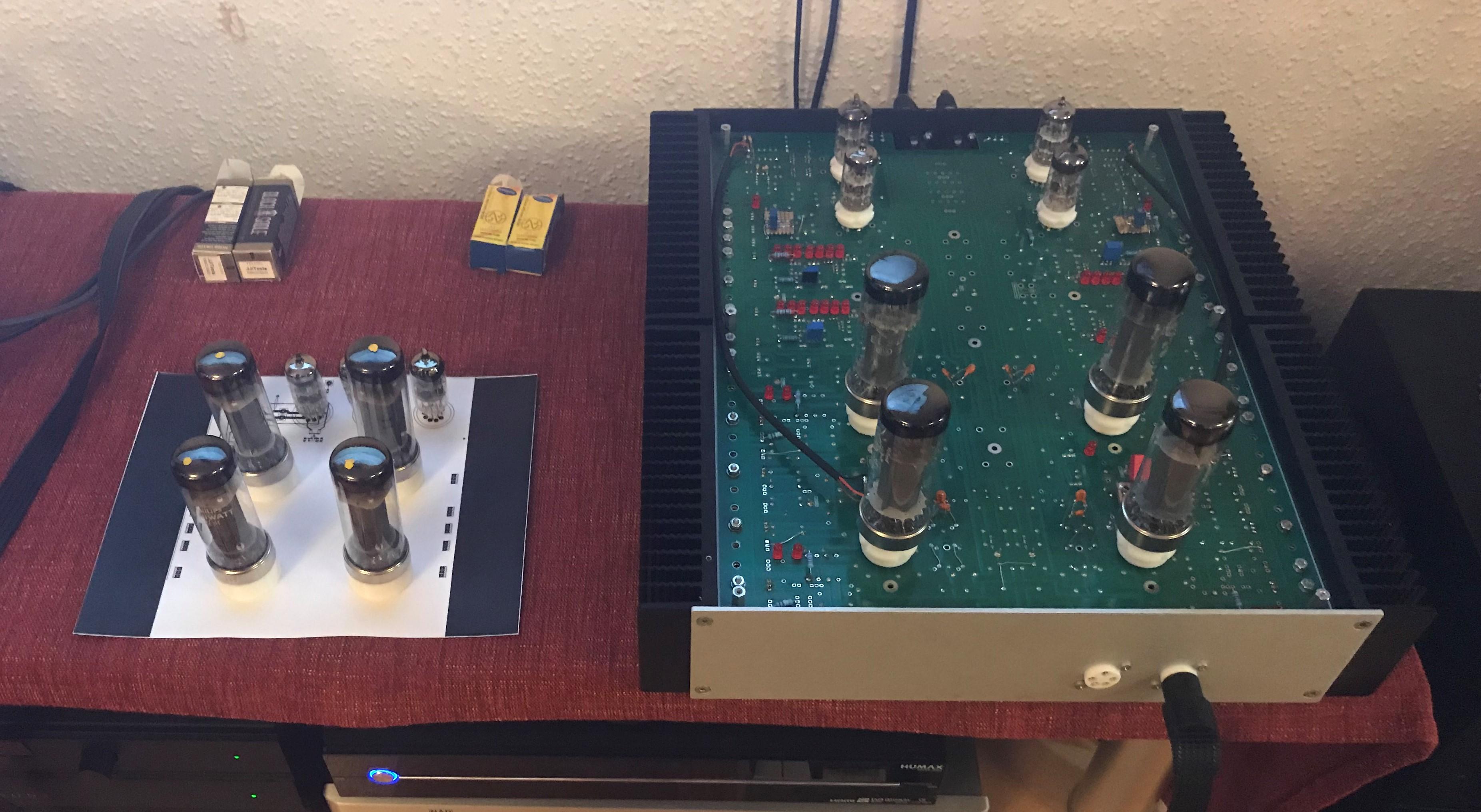
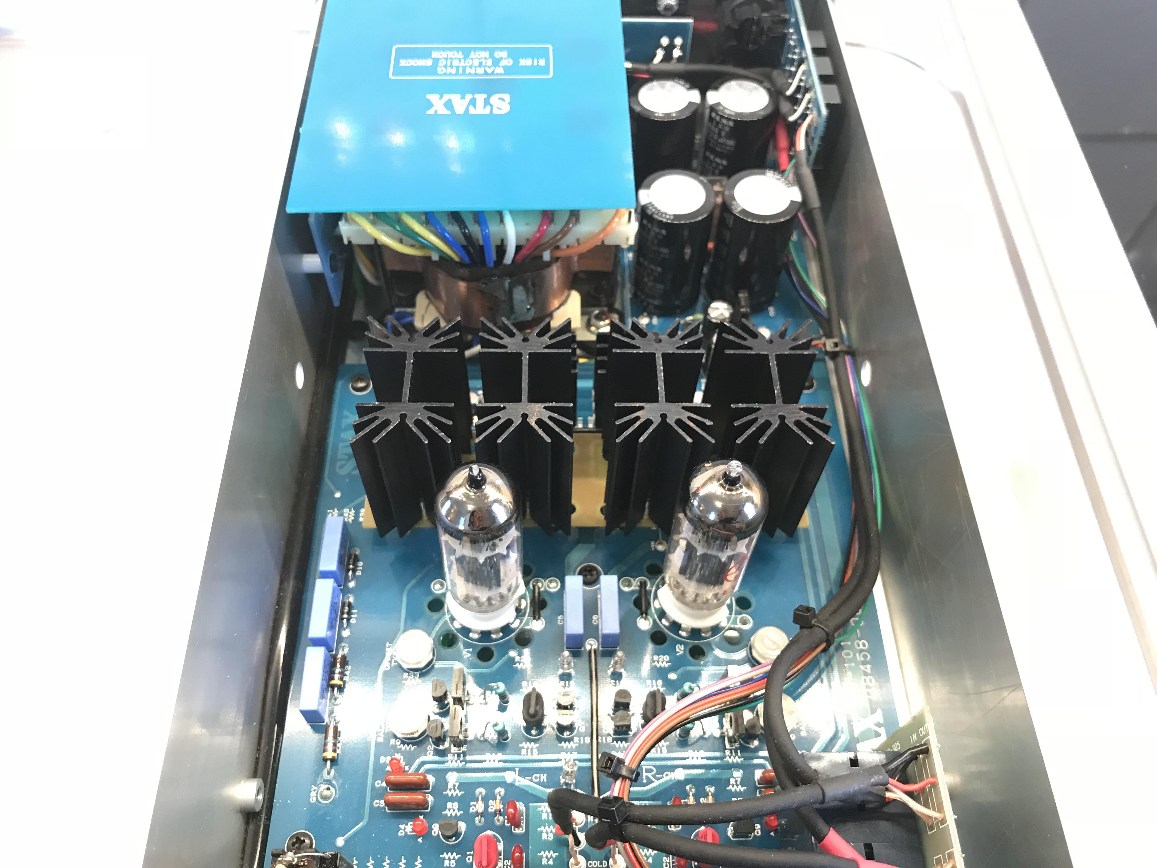
t2hvandlvpsukgsshv2 is one of two power supply boards for T2. It has +/-500V, BIAS (580V), +/-12V and Stax version of delay flashing LED during pre-heat and then steady. The second board is t2250kgsshv and has +250V, -560V and a 300V section to achieve -260V. I build a PSU with this boards some years ago to meet my preferences.
-
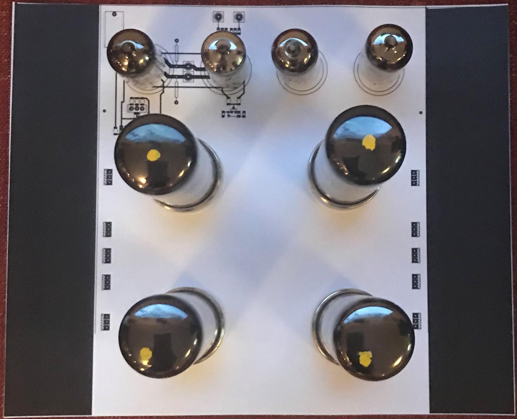
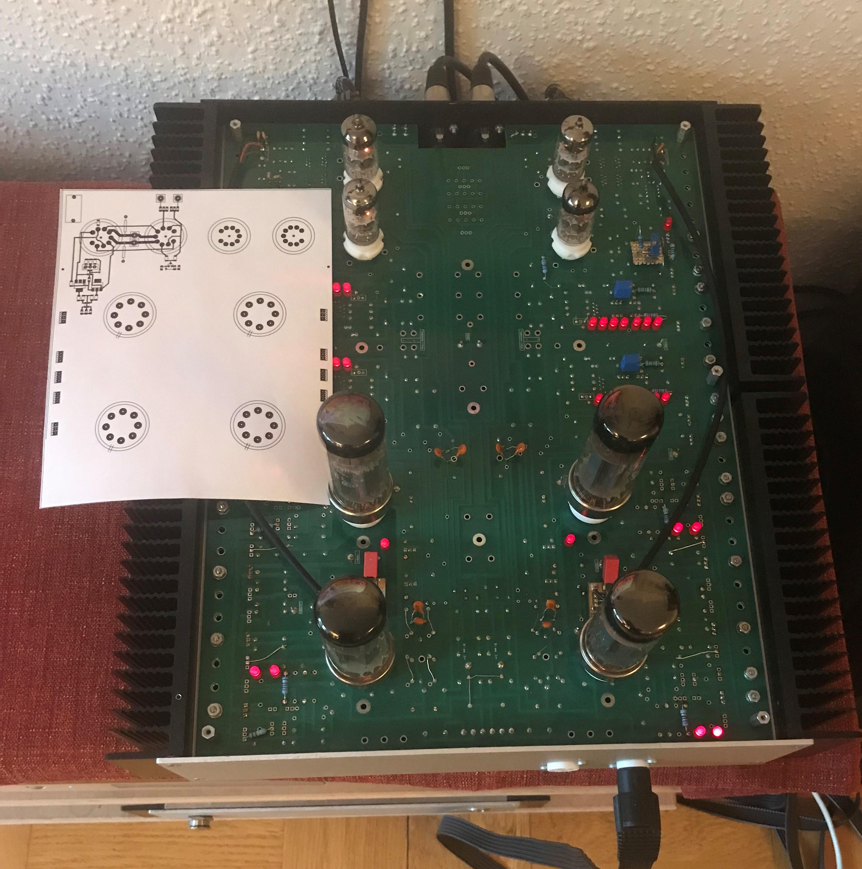
More paper work. Width incl. heat sinks 9.5in and length 7.9in. No angel brackets sands mounted direct on heat sinks, saves 1.6in.

-
Trying to use the above draft in a board layout. The print out is roughly a quarter of the original DIY T2 board in size. Output section reminds of T2 less unnecessary parts. This is progressing very slowly and I’m thinking it might go into trash can before it gets to the CNC router. Hmm.. probably trash can.
-
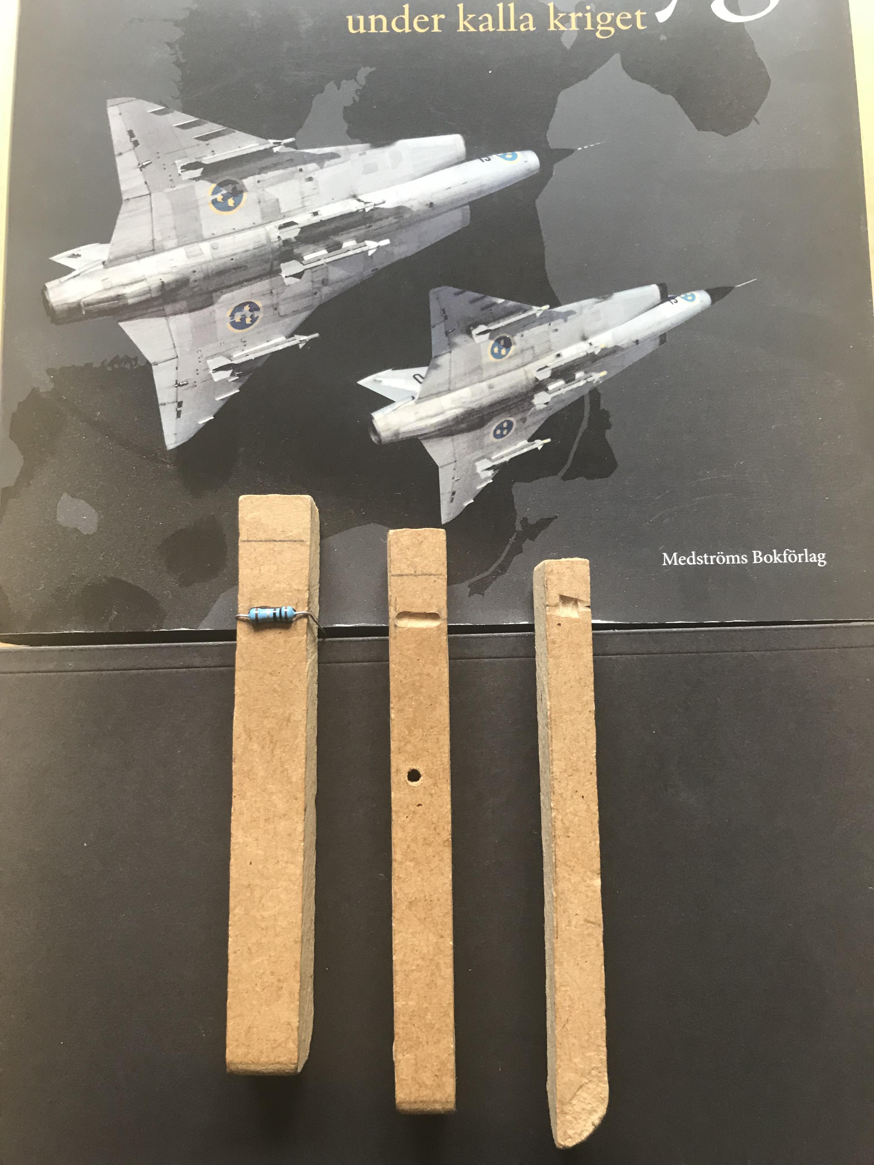
I made those three tools when building my first T2. Bending resistors and diodes...a piece of cake.
-
In April I reduced the 500 V and 560 V sections by a 100 volts. I’m satisfied with the results so from now on 400 V will be my first choice. Today I’ve reduced the positive 250 V to 220 V. It shouldn’t effect the quality of sound at all.
-
Interesting, keep on the testing and tell us your findings.
- 35 replies
-
- 1
-

-
- stax
- kevin gilmore
- (and 3 more)
-
The DY294 is of course only to check the breakdown voltage of a device. Additional to the DY294 I use MK-168 transistor tester (ebay from China) which seems to do quite well. If difficulties sourcing original parts some of them could very well be replaced with now in production pieces.
-
I suggest you use the DY294 tester. It will give you a pretty good hint if the device is OK.
-
I did retire early...
-
My name on the schematic and layout files are KG Tube input + GG output.*. Based on Kevin’s KGSSHV-TUBE-SANDWICH board. Different CCS, offset/balance servos and most parts are surface mounted. I did pollute the stax t8000 clone (well sorta) thread with posts during built last summer - an extremely rainy summer.
-
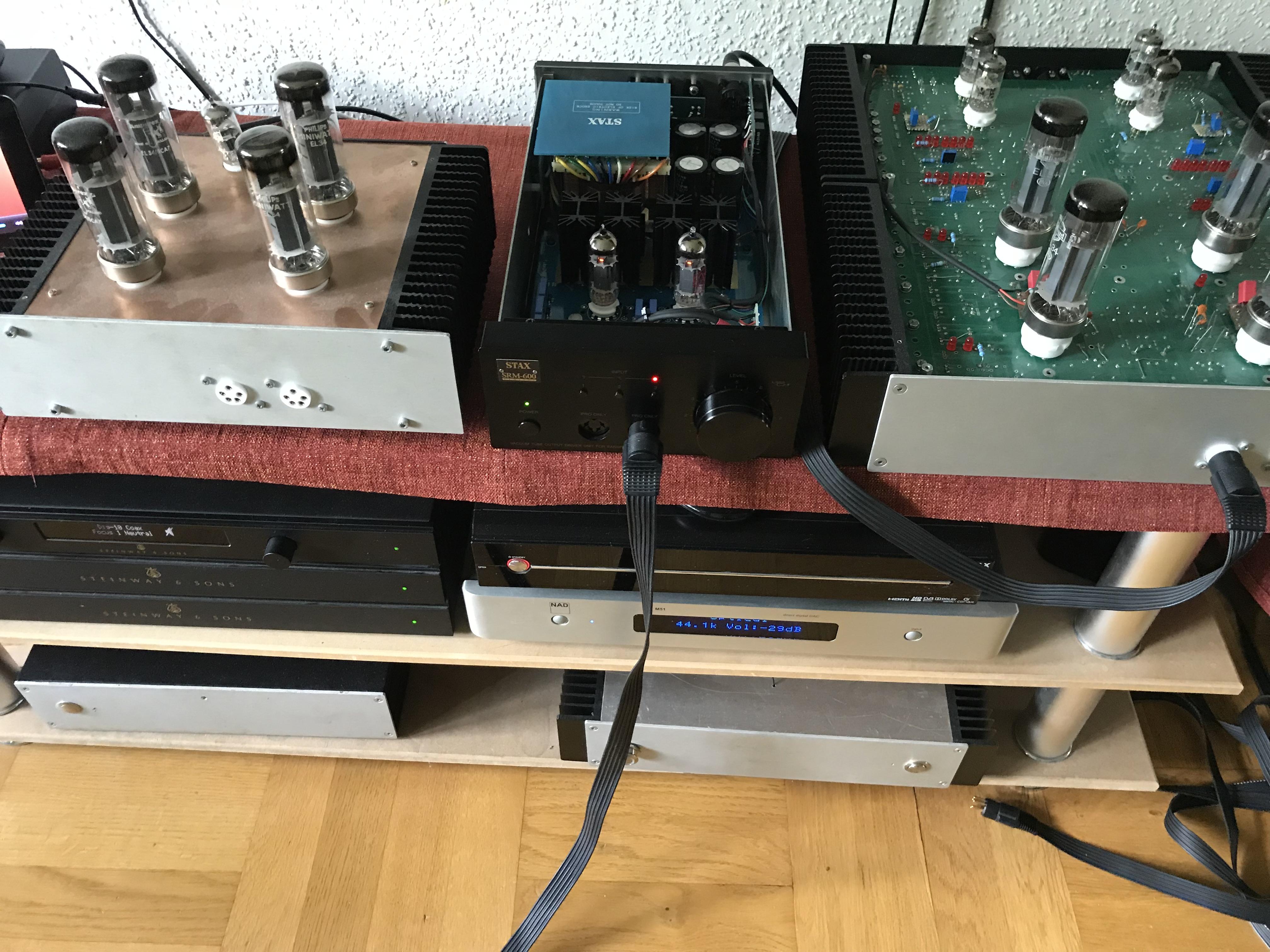
I’m presently enjoying the Schwanensee from Wiener Staatsoper through “SRM-600 Limited Modified” and I like the sound. Drove 400 km from our summer cottage to apartment and back today to assemble the CCS board. Here is picture of the Limited surrounded by a couple of nice electrostatics.
-
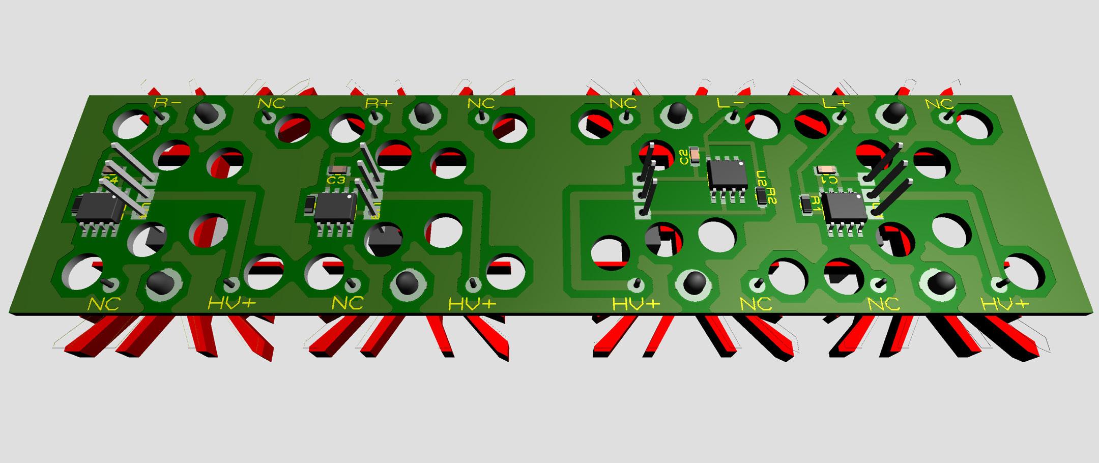
…limited. It’s a Stax SRM-600 Limited. Now I’ve got it modified with constant current sources instead of the power resistors. The CCSs are 01N100D/LT1021 by Kerry – see this post. The board looks like this and is connected to the main board via 16 pin headers to the holes for power resistors. Current sources set to 6.0 mA.
-
I got my first road bike, a Trek, three months ago. Occasionally I reach 45 km/h in moderate downhill slope straight forward - if it goes faster I use the brakes. 80 km/h really impresses (scares) me. I would prefer the team’s bus, if no seat available I take a taxi…
-
Nice ride! You have any recording for the return? average 48 km/h…
-
Tripp... ...trapp... ...trull... ...limited.
-
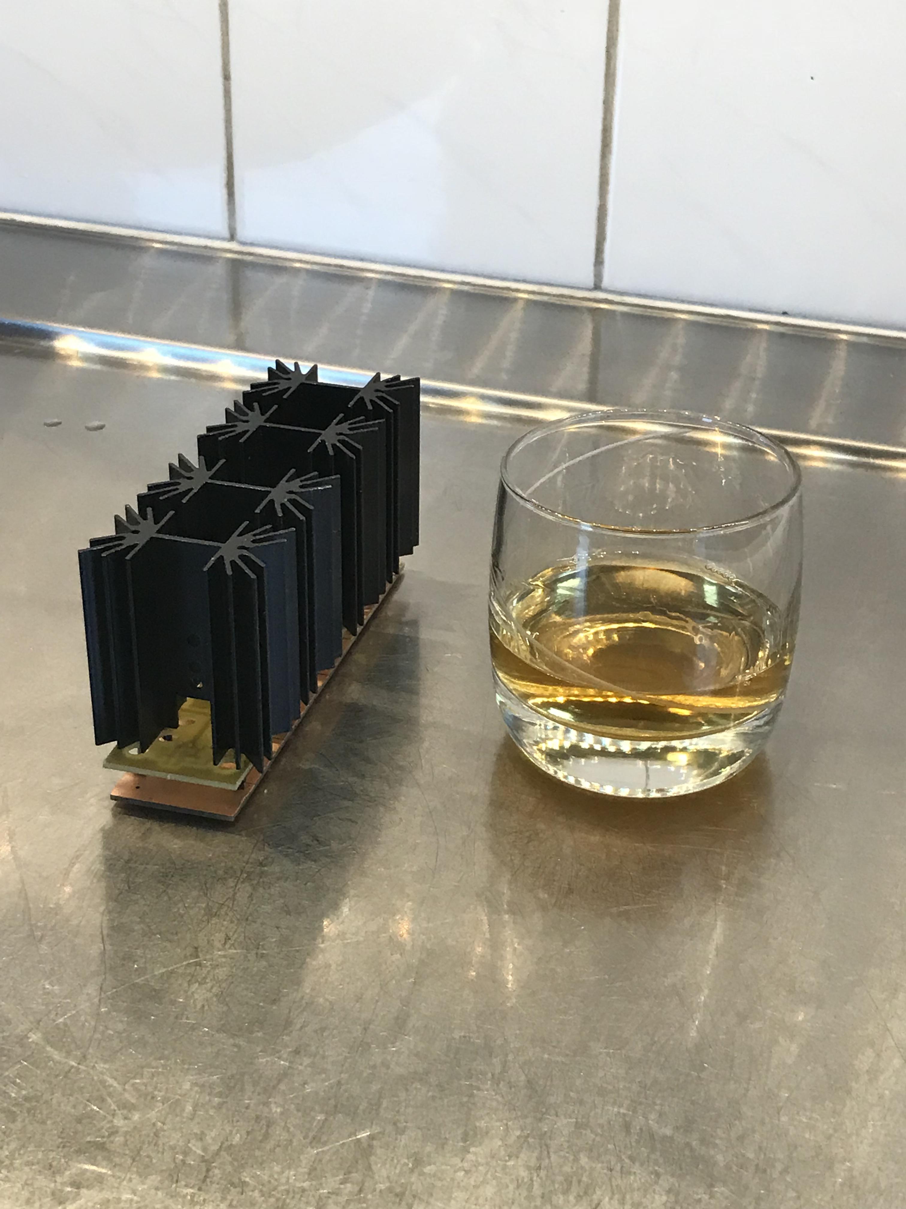
I've no problem with glasses. Using those.
-
Wow, a Kopparberg. Skål!
-
Happy Birthday Birgir!
-
Happy Birthday Kerry!
-
I believe ver 2.0 is taken – Kerry’s shrinked smd…
-
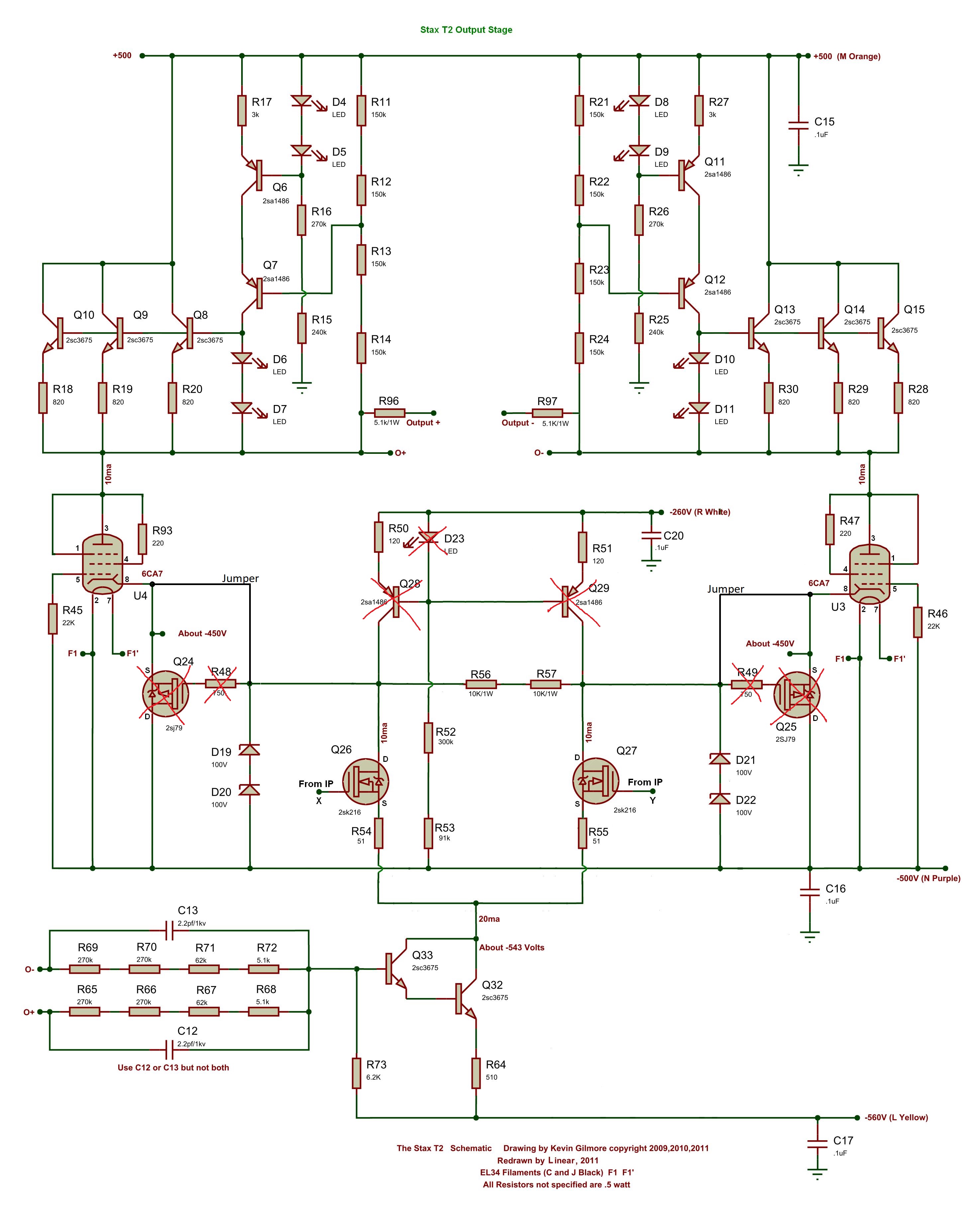
My T2 PSU differs some from the original DIY T2 PSU as I have a -560V section which is as capable as the -500V. So with this modification the only work the -500v is doing is to set the 6CA7 G1 potential. LTspice simulation I’ve done indicates that -500V at G1 might be desirable. But I don't trust myself doing this kind of work in LTspice. Below schematic: removed Q24,Q25,Q28,Q29,LED, R48,R49. Added jumpers between drain k216 and cathode 6CA7.
-
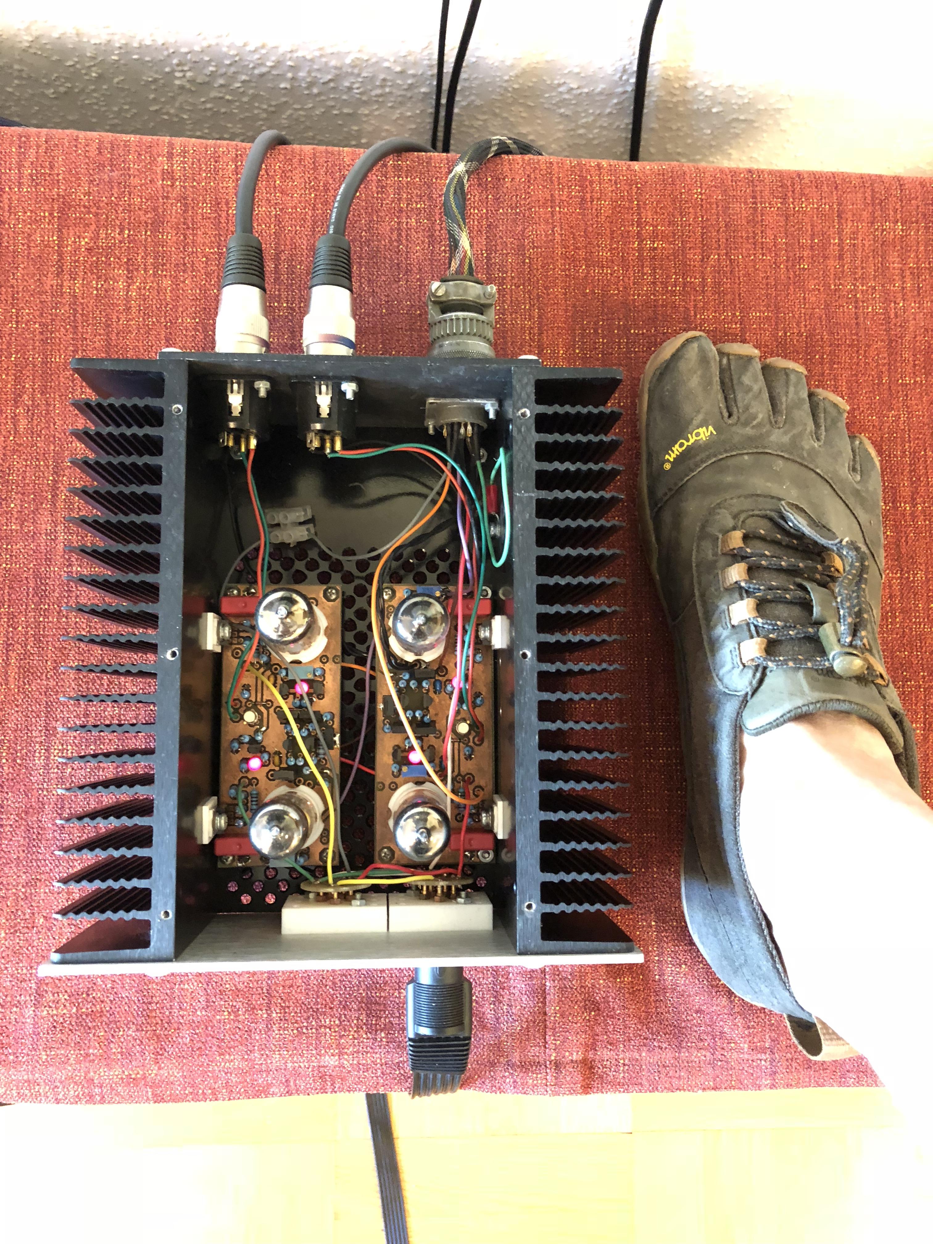
I had to open up the KGST for adjustment since I lowered the rail voltages. Four plain old good trimmers. My right foot for size comparison.
-
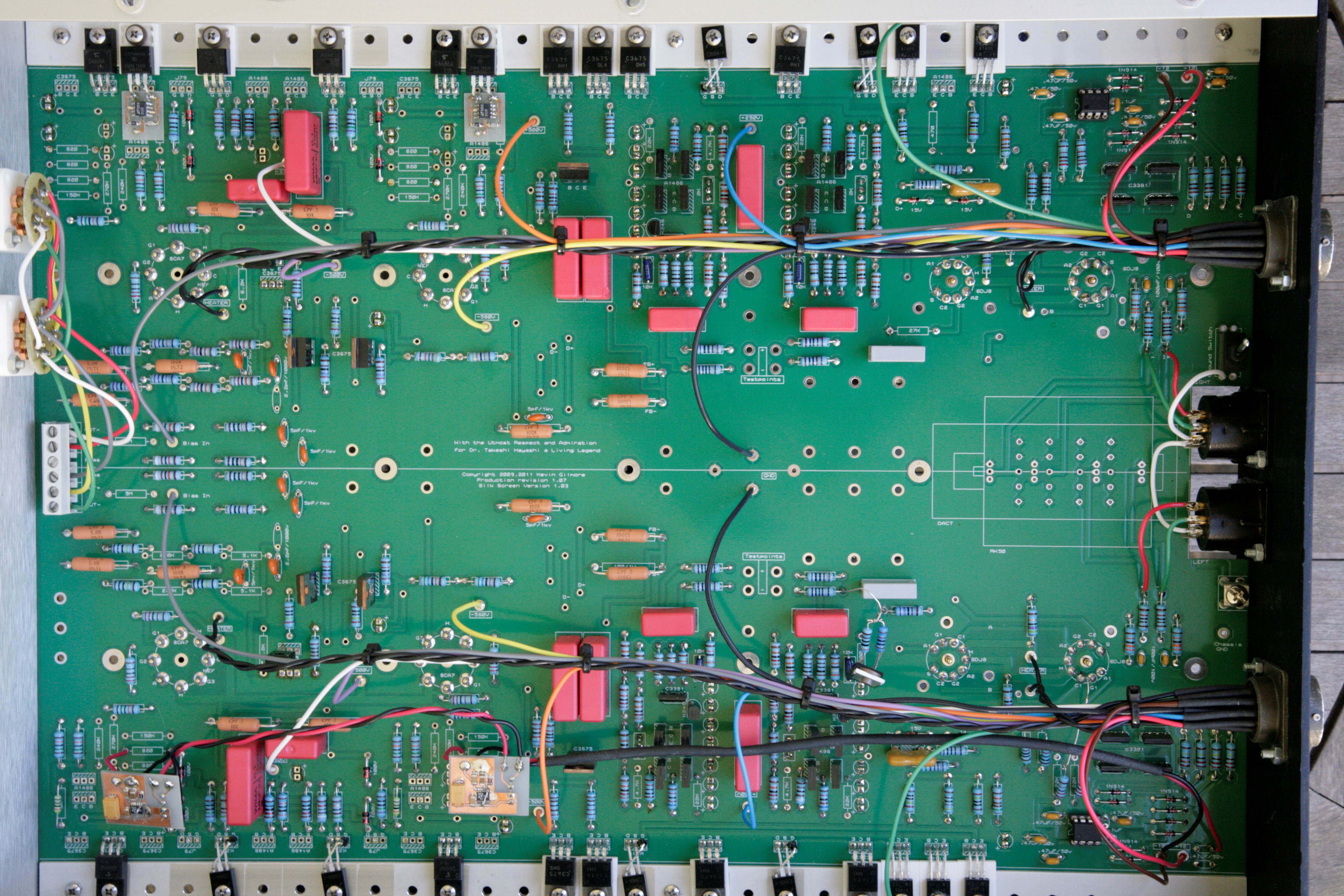
Thanks a lot George, but I actually have a small stock of j79/k216 myself. Living in the middle of nowhere you need to be prepared. Have been socializing with the faulty channel today and we are now both happy again. Maybe it’s more of a Grounded Grid with dual tube input and active batteries than a T2. Picture below shows the modded T2. No j79/a1486 at the output stage. Upper right the middle a1486 is missing – replaced with resistor so upper tube grid voltage is set by a voltage divider. If you have a well defined supply voltage you don’t need to send 2.5mA through a 27K resistor – I think.
-
Happy Birthday!