JoaMat
-
Posts
1,465 -
Joined
-
Last visited
-
Days Won
16
Content Type
Profiles
Forums
Events
Everything posted by JoaMat
-
and this Bergquist pad is supposed to be used without thermal grease.? Looks like a nice alternative.
-
......won’t stop us from doing all kind of crazy things. I've a secret - don't tell... I never use thermal paste
-
Thank you. I’m particular interested with the insulating shoulder 7721-3PPSG as I believe this part is essential for the combo.
-
I use ceramic insulator, insulating washer 7721-3PPSG and steel screws. The washer shaft is long enough to stick down in ceramic insulator a mm or so. I think this combination is used by more people than myself. Can you test this combination (or you already did?)? Preferable with some messy non-conductive thermal paste.
- 35 replies
-
- 1
-

-
- stax
- kevin gilmore
- (and 3 more)
-
@Kung Interesting. Can you provide more information, pictures etc. of what you’ve done? I love all kind of modifications.
-
What determines if a test passes or fails.
-
I usually work with imperial system in Proteus as I find it pretty convenient. For my 10K Afternoon Run the metric system is way more comfortable. The voltage cross 2sa1486 is 580 – 590 V. That’s why I chose between stn9360 and 2sa1486. I guess you could use a pair of ksa1156 and split the voltage cross them.
-
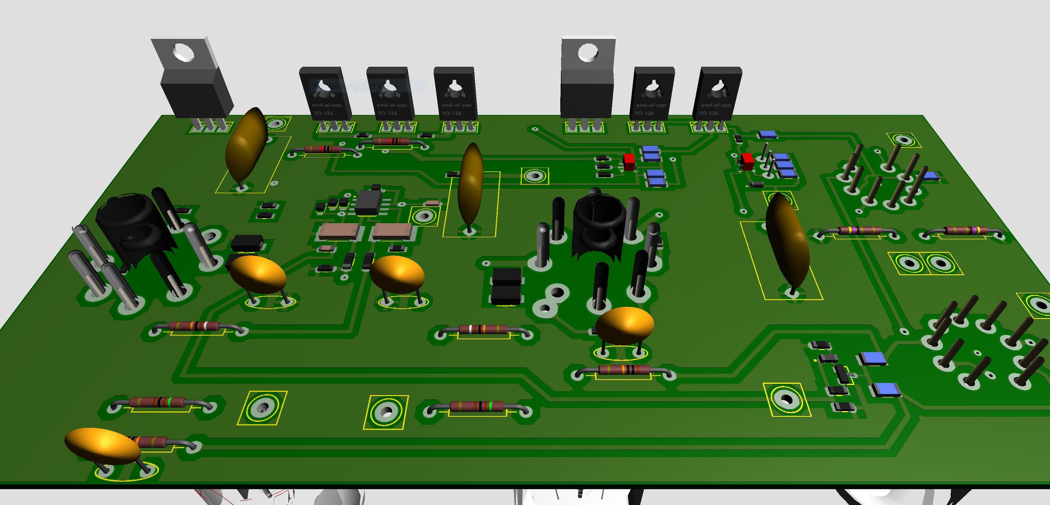
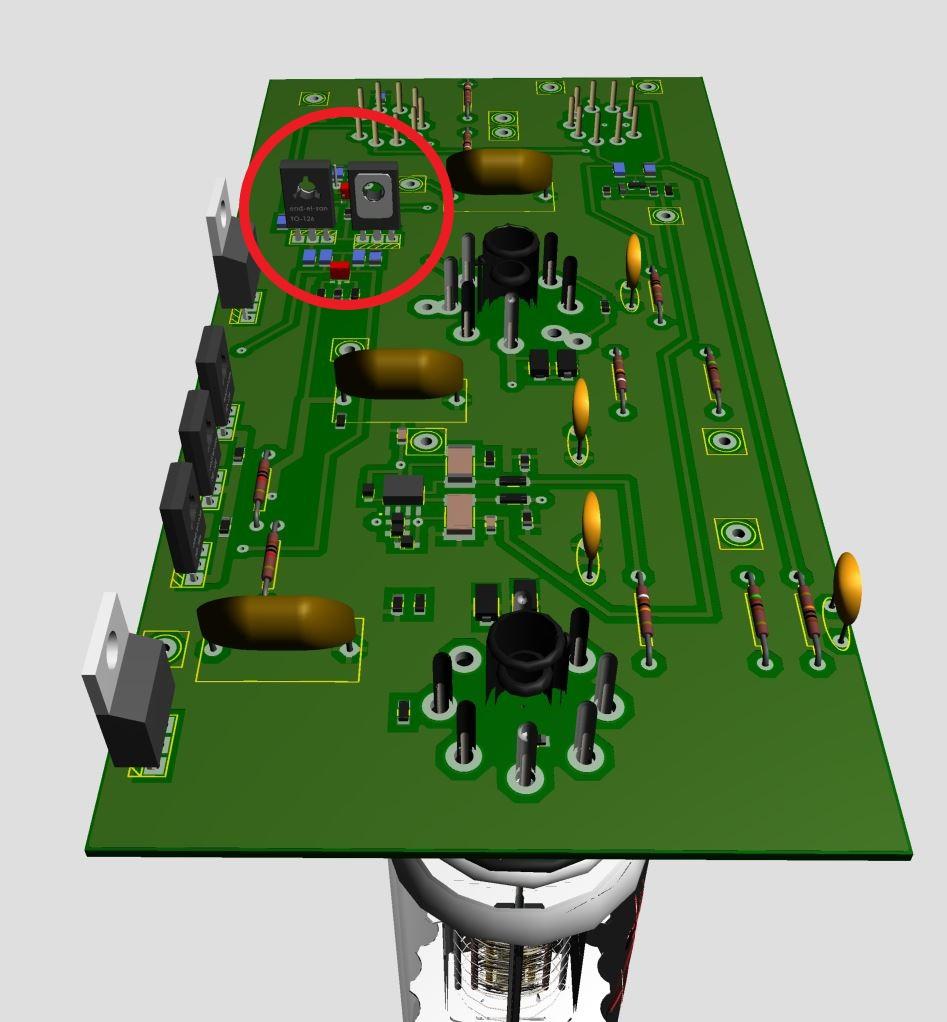
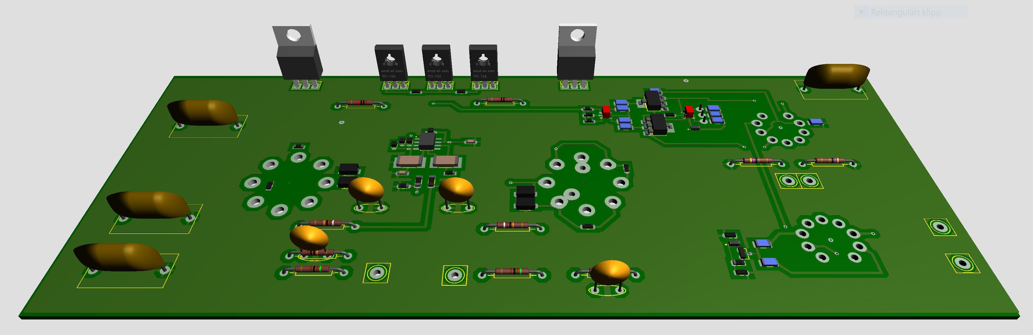
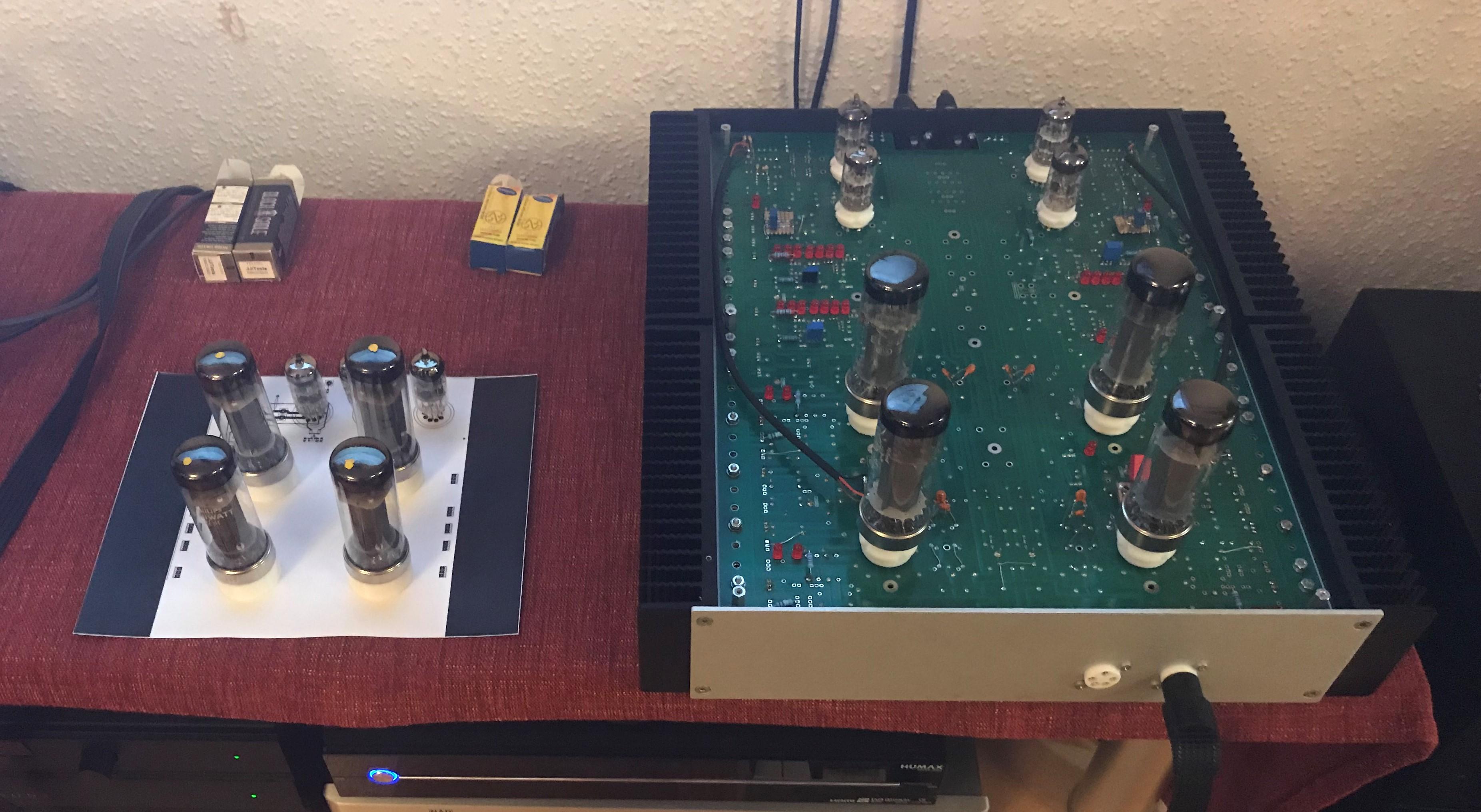
Thanks for feedback Birgir. Moved a1486s to main heat sink. Kind of work that’s easily done with help of netlist and a glass of doublewood 12 years. Hmm... should move a1486s half an inch to the right.

-
The two fellows in the red circle are 2sa1486. Roughly 800mW each, maybe to-126 is a better choice than smd stn9360…
-
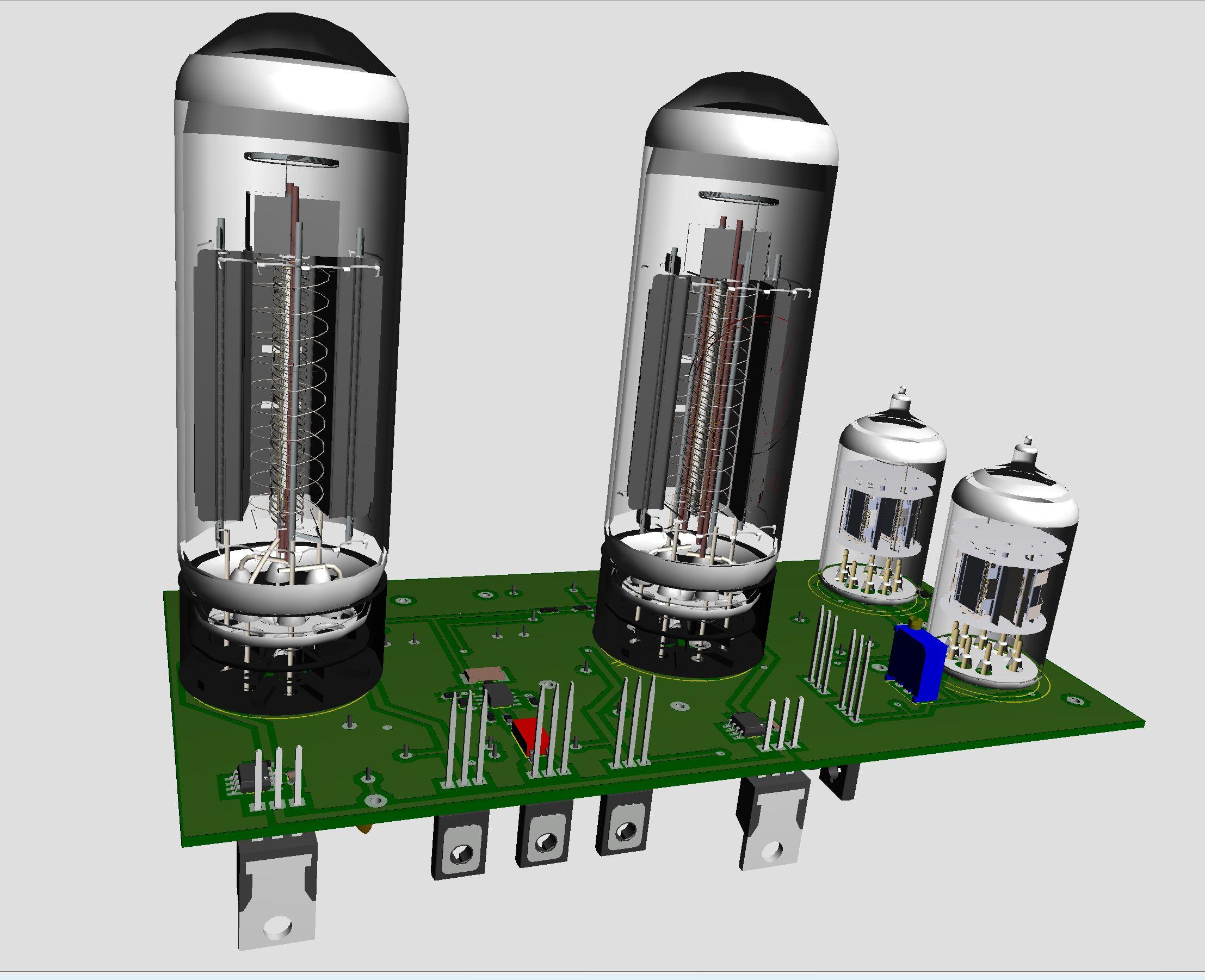
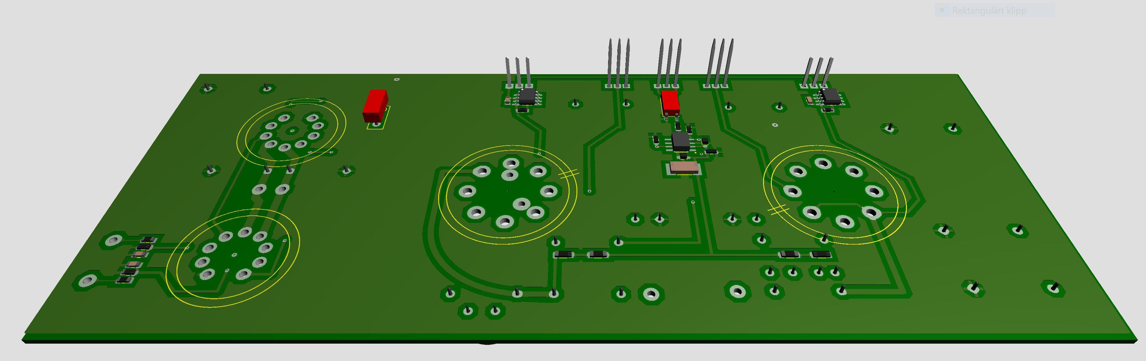
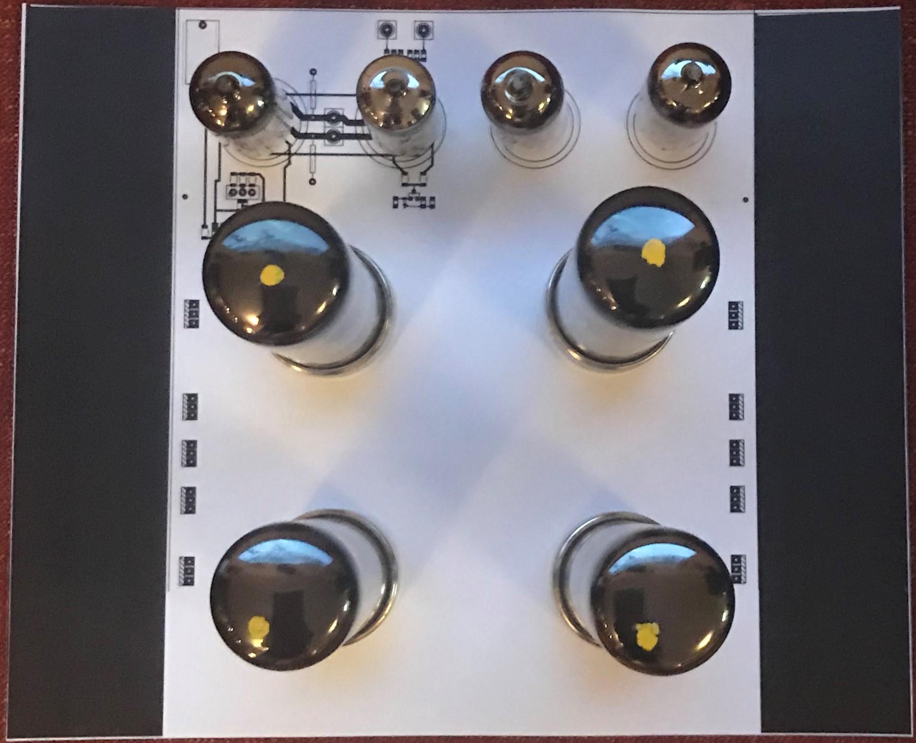
Still in progress. Board shortened now 160mm x 80mm. Found models of tubes on the internet. The small tubes even have golden pins. I got the tube models from grabcad.com and the creator of EL34 and small tube (12AX7) is Andrew Whitham, United Kingdom.
-
sun factor 15 will do
-
In T2 one tube act as lower and the other tube as upper device. Another way would be to have one tube for each side. This adapter board changes to single tube per side. The T2 way makes the layout a bit more elegant then single tube per side. Else pro/cons - I have no idea… anyone?
-
I use 8.5 but I came cross 8.6 just to find out that it had some funny behavior that I didn’t understood so I went back to 8.5. The beauty with not backward combability is that you can read my files but I can’t read yours… 8.3 - 8.4 - 8.4 ….. 8.8 non- backward combability. Just love that business model.
-
Great! Now I get it - becoming an expert. Thank you! Which version are you folks working with?
-
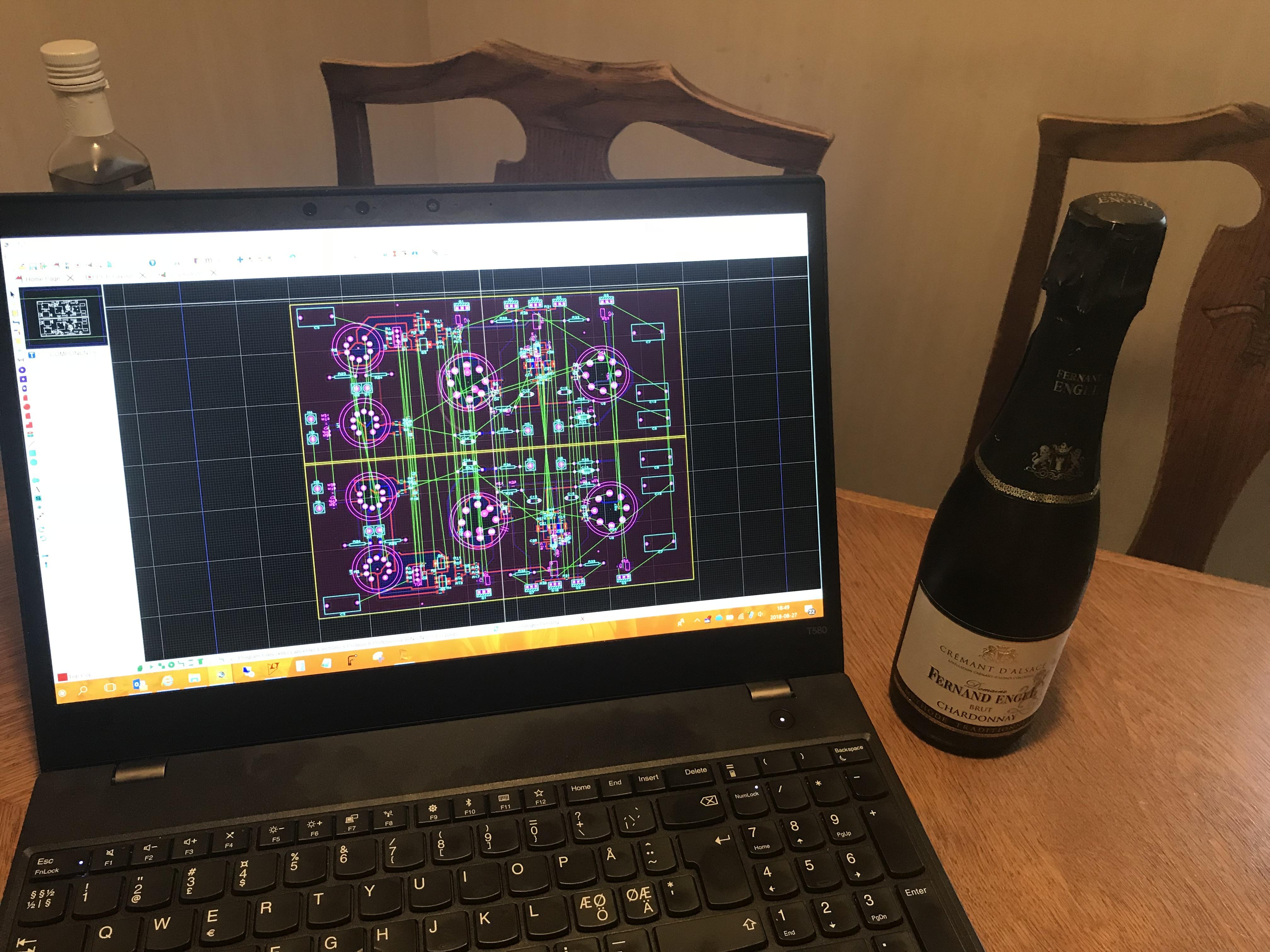
Is it possible to netlist a board without an associated schematic?
-
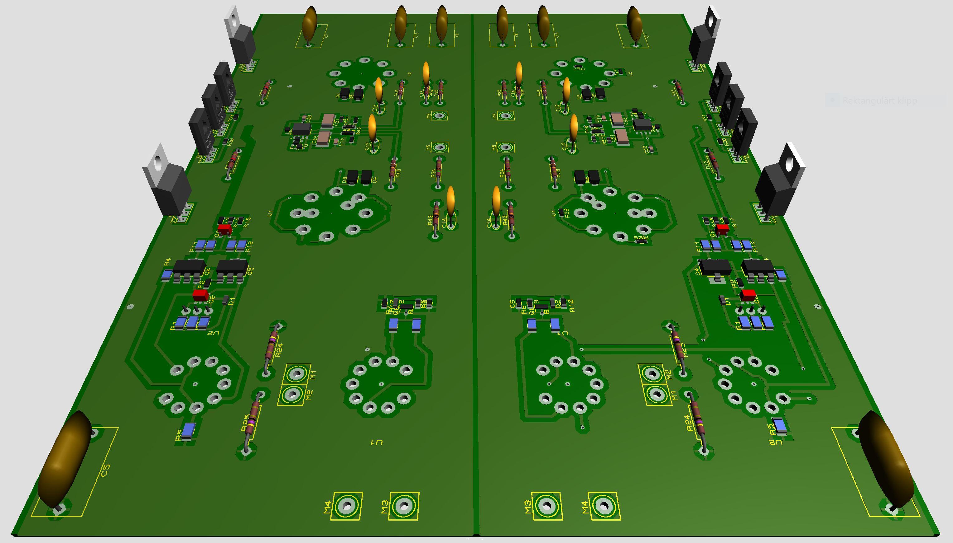
Left and right sides ready? Seems to be some errors to fix. And wife got a new assignment - to be celebrated…
-
You guys have it in you - the schematic in your heads. I’ve no head and therefor I use schematic which I derive from your layouts hihihihi
-
All components are now on the right channel board. More work is to be done but so far it has gone quite nice. By the way, I think I've learned netlisting and I love it - tells me when I'm out of track.
-
Thanks. Yep, your micro power supplies are very interesting. My idea is to make a PSU with +/-15V, +220V, +400V and -460V. Shooting from the hip - how about producing 580V (BIAS) by GRHV?
-
t2hvandlvpsukgsshv2 is one of two power supply boards for T2. It has +/-500V, BIAS (580V), +/-12V and Stax version of delay flashing LED during pre-heat and then steady. The second board is t2250kgsshv and has +250V, -560V and a 300V section to achieve -260V. I build a PSU with this boards some years ago to meet my preferences.
-
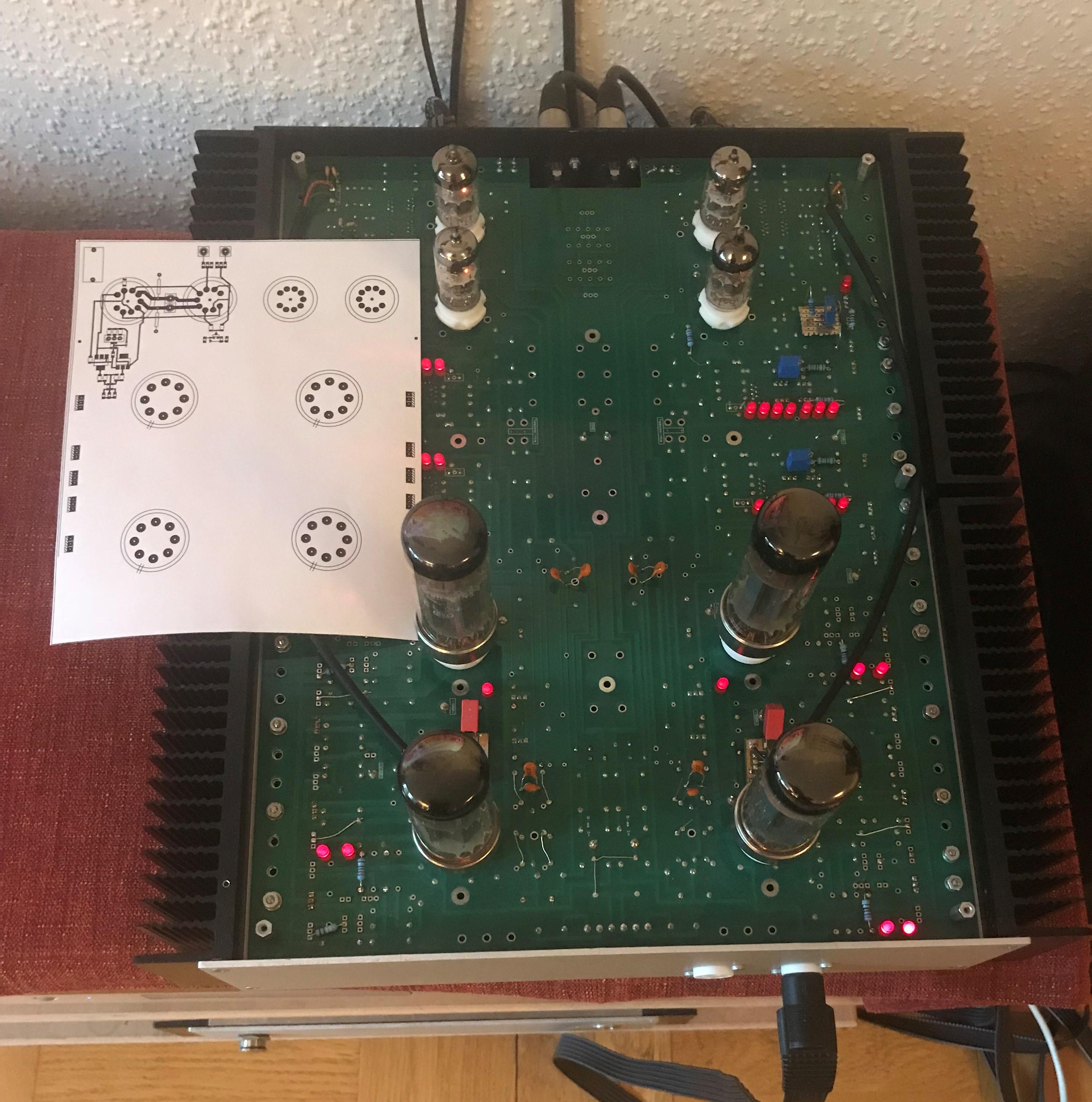
More paper work. Width incl. heat sinks 9.5in and length 7.9in. No angel brackets sands mounted direct on heat sinks, saves 1.6in.
-
Trying to use the above draft in a board layout. The print out is roughly a quarter of the original DIY T2 board in size. Output section reminds of T2 less unnecessary parts. This is progressing very slowly and I’m thinking it might go into trash can before it gets to the CNC router. Hmm.. probably trash can.
-
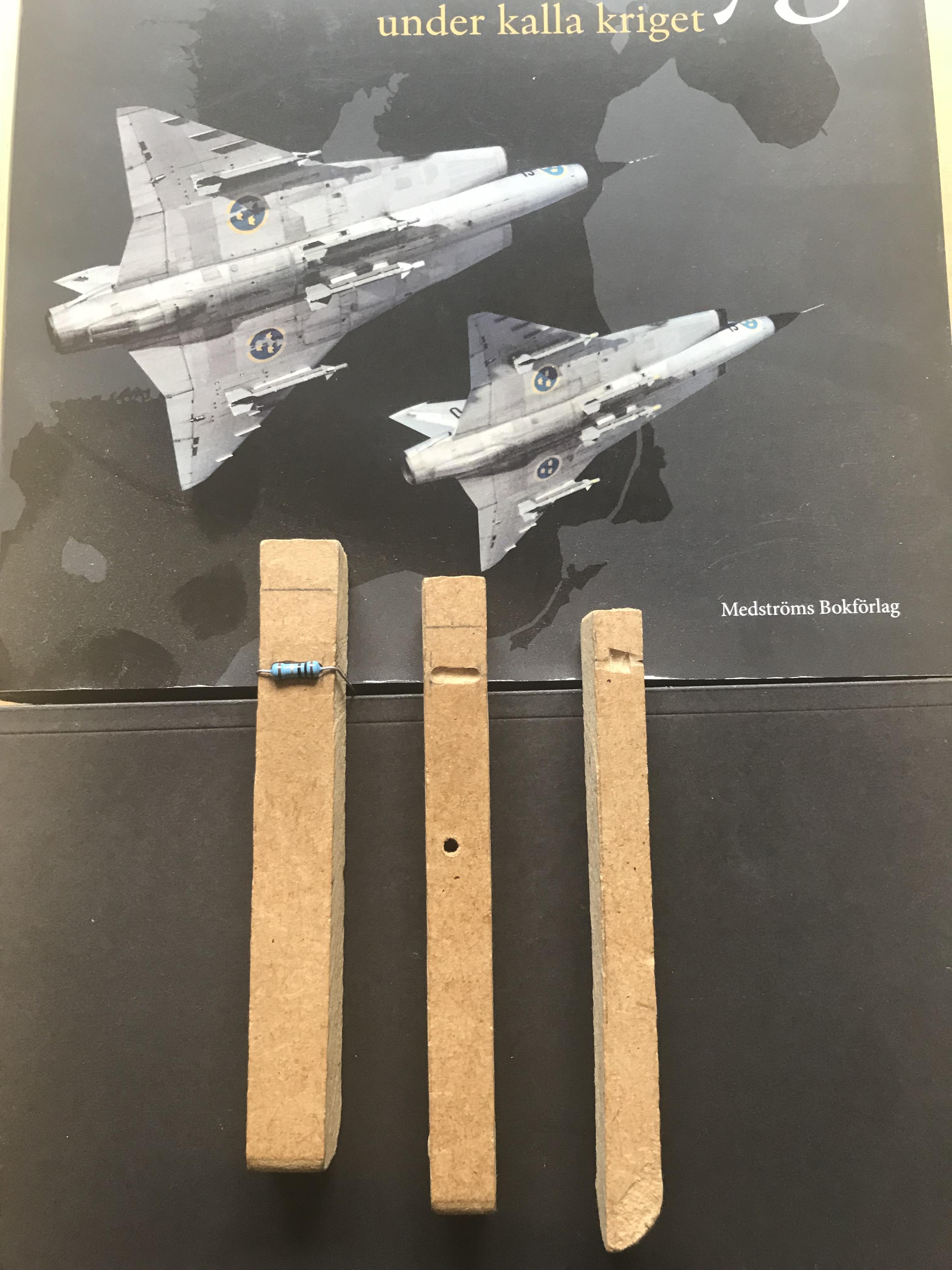
I made those three tools when building my first T2. Bending resistors and diodes...a piece of cake.
-
In April I reduced the 500 V and 560 V sections by a 100 volts. I’m satisfied with the results so from now on 400 V will be my first choice. Today I’ve reduced the positive 250 V to 220 V. It shouldn’t effect the quality of sound at all.
-
Interesting, keep on the testing and tell us your findings.
- 35 replies
-
- 1
-

-
- stax
- kevin gilmore
- (and 3 more)